
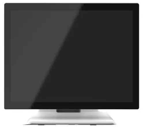
MicroTouch DT-150P-M1 Medical-Grade Monitor
Overview
The DT-150P-M1 series is a 15” touchscreen monitor that builds to withstand a commercial-grade open frame monitor, with a stylish thin cable management bracket and versatile design DT-150P-M1 is an exceptional choice for applications for all business sectors and well suited for point-of-sale, point-of-information, point-of-service and interactive signage.
Feature
- Cable management bracket design for easy organizes cable.
Specifications
| LCD Touch Panel | |
| Size | 15” TFT LCD |
| Brightness | 350 cd/m2 (Non-touch screen) 297 cd/m2 (P-cap touch with AG Coating) |
| Number of Pixels | 1024 (H) × 768 (V) |
| Touch Type | P-CAP/ 10 points |
| Environment | |
| Certificate | CE, CB, FCC, UL, CCC, RoHS, IEC60601-1-2 4th edition compliant |
| Compliance | Front Panel IP54 |
| Operating Temperature | 0°C ~ 40°C |
| Storage Temperature | -20°C ~ 60°C |
| Operating Humidity | 20% ~ 80% RH, non-condensing |
| Mounting | VESA 100 mm x 100 mm |
| Dimension (W x H x D) | 337.4 mm x 304.2 mm x 200.9 mm |
| Net Weight | 4.4 kg |
| Gross Weight | 6 kg |
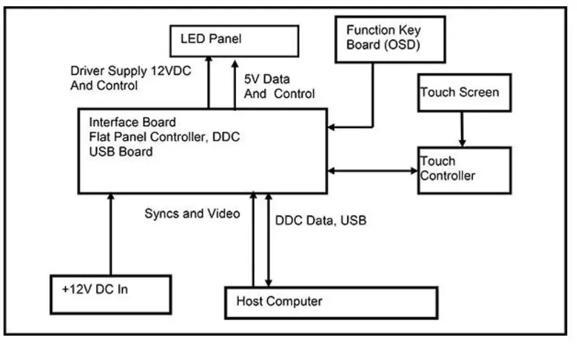
Block Diagram
Interface Connectors
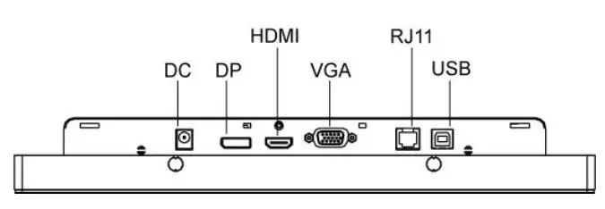
Power Connector
The DC power via external 12V Adapter provide it
Video Signal Connector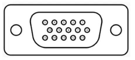
VGA
The video signal input via D-type 15-pin female connector. Connector Pin Assignment:
|
VGA The video signal input via D-type 15-pin female connector. Connector Pin Assignment: | |
| Pin | Signal |
| 1 | RED |
| 2 | GREEN |
| 3 | BLUE |
| 4 | NC |
| 5 | GND |
| 6 | RED_RTN |
| 7 | GREEN_RTN |
| 8 | BLUE_RTN |
| 9 | +5V |
| 10 | GND |
| 11 | NC |
| 12 | SDA |
| 13 | HSYNC |
| 14 | VSYNC |
| 15 | SCL |
Display Port(1.2a)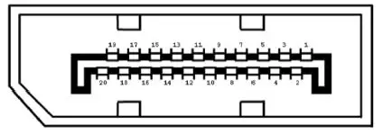
|
Display Port(1.2a) | |||
| Pin | Signal | Pin | Signal |
| 1 | ML_Lane 0(p) Data0 + | 11 | Signal ground |
| 2 | Signal ground | 12 | ML_Lane 3(n) Data3 – |
| 3 | ML_Lane 0(n) Data0 – | 13 | Signal ground |
| 4 | ML_Lane 1(p) Data1 + | 14 | Signal ground |
| 5 | Signal ground | 15 | AUX_CH(p) AUX + Signal for Auxiliary Channel |
| 6 | ML_Lane 1(n) Data1 – | 16 | Signal ground |
| 7 | ML_Lane 2(p) Data2 + | 17 | AUX_CH(n) AUX – Signal for Auxiliary Channel |
| 8 | Signal ground | 18 | Hot Plug |
| 9 | ML_Lane 2(n) Data 2 – | 19 | DP_PWR Return |
| 10 | ML_Lane 3(p) Data3 + | 20 | DP_PWR |
HDMI(1.3) (compatible with HDMI1.4)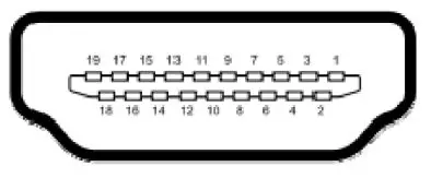
|
HDMI(1.3) (compatible with HDMI1.4) | |||
| Pin | Signal | Pin | Signal |
| 1 | TMDS Data2+ | 11 | TMDS Clock Shield |
| 2 | TMDS Data2 Shield | 12 | TMDS Clock– |
| 3 | TMDS Data2– | 13 | CEC |
| 4 | TMDS Data1+ | 14 | Reserved (N.C. on device) |
| 5 | TMDS Data1 Shield | 15 | SCL |
| 6 | TMDS Data1– | 16 | SDA |
| 7 | TMDS Data0+ | 17 | DDC/CEC Ground |
| 8 | TMDS Data0 Shield | 18 | +5V Power |
| 9 | TMDS Data0– | 19 | Hot Plug Detect |
| 10 | TMDS Clock+ | ||
Signal Connector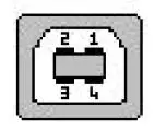
|
USB Connector | |||
| Pin | Signal | Pin | Signal |
| 1 | VCC | 3 | D+ |
| 2 | D- | 4 | GND |
RJ11 Connector (for Remote Key) (option)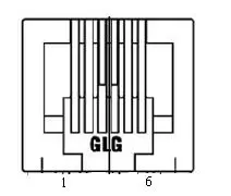
|
RJ11 Connector (for Remote Key) (option) | |||
| Pin | Signal | Pin | Signal |
| 1 | MENU | 4 | SELECT |
| 2 | UP | 5 | POWER |
| 3 | DOWN | 6 | GND |
Package Overview
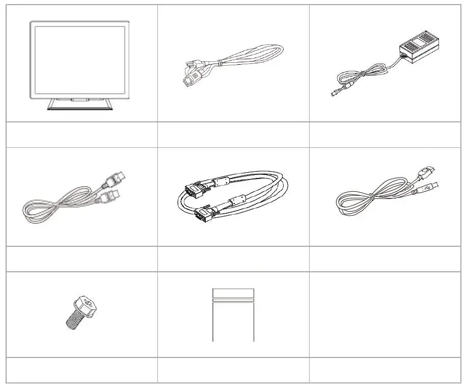
- LCD Display
- Power Cord
- DC Power Supply
- HDMI Cable
- VGA cable
- USB cable (A to B)
- M3 screw
- Zip bag
Warming!
This product is intended to be supplied by a Listed Power Adapter or DC power s ource, rated 12Vdc, 2.5A minimum, Tma = 40 degree C minimum, and the a ltitude of operation = 3048m minimum. If it needs further assistance with purc hasing the power source, please contact to MicroTouch for further information.
About VESA Mount
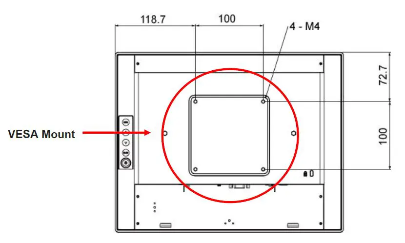
The DT-150P-M1 series conform to the “VESA Flat Display Mounting Interface Standard” which defines a physical mounting interface for touch monitor, and corresponding with the standards of touch monitor mounting devices. The VESA mount is located on the back of this unit.
Warming!
Please select the MicroTouch original screws! The distance between the back cover surface and the bottom of the screw hole is 8 mm. Please use four M4 screws diameter with 8-10mm proper length to mount your monitor.
Note: The mounting stand must be able to support at least 7.67 lbs (3.48 Kg).
On-Screen Display
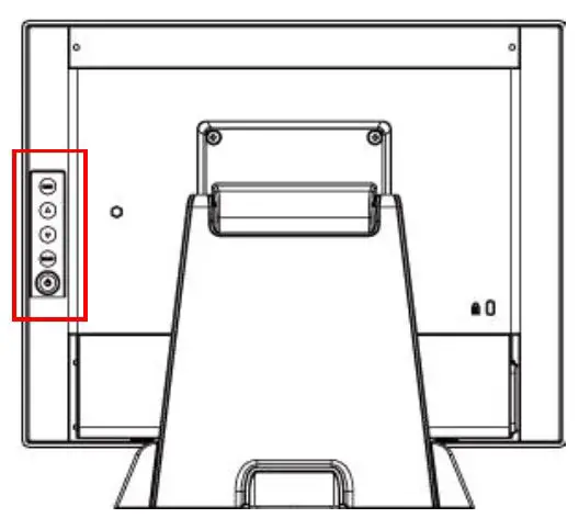
| OSD Key | Menu off status | Menu on status |
| MENU | Menu appear | Menu disappear/ return to main item |
| ▲ | Brightness | Main item select up/ Adjust up |
| ▼ | Contrast | Main item select down/ Adjust down |
| SELECT | Enter/Select sub-item function | |
| Power On/Off | ||
- Press the “MENU” button to pop up the “on-screen menu” and press “Up” or “Down” button to select among the four functions in the main menu.
- Choose the adjustment items by pressing the “SELECT ” button.
- Adjust the value of the adjustment items by pressing the “Up” or “Down” button.
- With the OSD menu on screen, press “ Menu” button to return main menu or exit OSD.
- The OSD menu will automatically close, if you have left it idle for a pre-set time.
- To Lock / Unlock the OSD / Power menu buttons, press “Menu” and “Minus” at the same time to select. OSD / Power the Lock / Unlock function.
Please note:- When the OSD Lock function is selected, this indicates that all the buttons except “power” button are now disabled.
- When the Power Lock function is selected, this indicates that the power key is disabled; user can not to turn off the monitor by “Power” key.
- To disable the touch function, press “Menu” and “Enter” Key, at the same time.
- To enable the touch function, press “Menu” and “Enter” Key, at the same time for five seconds.
- Press the power key button, there will be an OSD window pop up to ask if it should be going off. If press the power key in five seconds, the monitor power will be off. If don’t press the power key in five seconds, the OSD window will be gone and return to the normal status instead.
- Direct input select function.
- Normal:Press and keep pressing “Select” key for 3 seconds, will change to pop up “source select” OSD.
- Sleep status:Press and keep pressing “Select” key for 1 seconds, will change to pop up “source select” OSD.
- Factory mode: Press the “MENU” button to pop up the “on-screen menu” and select “Option” icon in “Factory” item, key in password “3”,”3″,”3″,”3″ into factory mode.
- Burn-in mode: In Factory mode to select “Burn In” item into Burin-in mode (unplug signal cable or do not enter the signal source).
- Work time: In factory mode, displays monitor the work time counting in hours.
OSD Function Description
| Item | Content | Default |
| Contrast | The monitor luminance level control. | 50 |
| Brightness | The monitor backlight level control. | 100 |
| H-Positon | Moving screen image horizontal position to left or right. | NA |
| V-Positon | Moving screen image vertical position to up or down. | NA |
| Phase | The screen image horizontal dot clock adjustment. | NA |
| Clock | The screen image pixel phase adjustment. | NA |
| Auto Adjust | Fine-tune the image to full screen automatically. | NA |
| Color Temp | Color temperature selection. (9300K, 6500K, 5500K, 7500K, User) | USER |
| Medical models: Sharpness | Adjust the screen sharpness. | 50 |
| Medical models: Gamma | Gamma / DICOM function mode. (Native, 1.8, 2.2, DICOM) | Native |
| OSD Timeout | OSD auto-disappear time selection. | 15 |
| Medical models: OSD Positon | Moving OSD menu position. | User |
| OSD H-Positon | Moving OSD menu horizontal position to left or right. | 50 |
| OSD V-Positon | Moving OSD menu vertical position to up or down. | 50 |
| Reset | Factory default value restored. | NA |
| OSD Language | OSD menu language selection. ( English, French, Deutsch, Italian,Spanish, Japanese, Traditional Chinese and Simplified Chinese) | English |
| Source Select | Select Input function.(Auto, VGA,HDMI,DP) | Auto |
| Medical models: Display port | Display current resolution related information. | NA |
| Medical models: Lum Preset | The monitor backlight function quick mode. (Set1, Set2, Set3, User) | User |
| Factory | Factory mode related adjustment items. | NA |
Timing Table Chart
| Mode | NO | Resolution | H-Freq. (KHz) | Band Width (MHz) | Polarity | |
| H | V | |||||
| 1 | 102 | 720×400 70Hz | 31.47 | 28.322 | - | + |
| 2 | 103 | VGA 640×480 60Hz | 31.47 | 25.175 | - | - |
| 3 | 182 | MAC 640×480 66Hz | 35 | 30.24 | - | - |
| 4 | 173 | 640×480 72Hz | 37.86 | 31.5 | - | - |
| 5 | 109 | 640X480 75Hz | 37.5 | 31.5 | - | - |
| 6 | 104 | 800×600 56Hz | 35.16 | 36 | + | + |
| 7 | 116 | 800×600 60Hz | 37.88 | 40 | + | + |
| 8 | 110 | 800×600 72Hz | 48.077 | 50 | + | + |
| 9 | 117 | 800×600 75Hz | 46.875 | 49.5 | + | + |
| 10 | 108 | 832×624 (74.55Hz) | 49.722 | 57.28 | - | - |
| 11 | 118 | 1024×768 (60.0 Hz) | 48.363 | 65 | - | - |
| 12 | 157 | 1024×768 (70.0 Hz) | 56.476 | 75 | - | - |
| 13 | 141 | 1024×768 (75.0 Hz) | 60.02 | 78.75 | + | + |
EDID Data
VGA
The monitor assembly shall provide a display communications channel that conforms to VESA DDC2B hardware requirements. This configuration shall contain the 128-byte EDID file as specified by VESA EDID Standard
DP/HDMI
The monitor assembly shall provide a display communications channel that conforms to VESA DDC2B hardware requirements. This configuration shall contain the 256-byte EDID file as specified by VESA EDID Standard
Dimension
Front View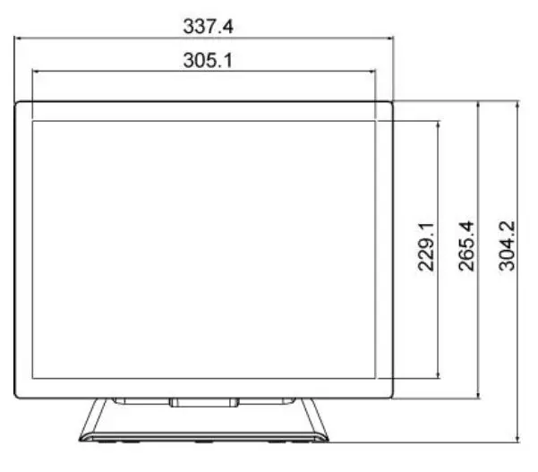
Side View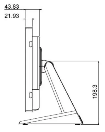
Rear View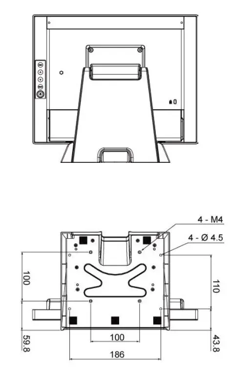
Declaration of the Presence Condition of the Restricted Substances Marking
Note 1:〝Exceeding 0.1 wt %〞and〝exceeding 0.01 wt %〞indicate that the percentage content of the restricted substance exceeds the reference percentage value of presence condition.。
Note 2:〝○〞indicates that the percentage content of the restricted substance does not exceed the percentage of reference value of presence.
Note 3:The〝−〞indicates that the restricted substance corresponds to the exemption.
Compliance Information
For FCC (USA)
This equipment has been tested and found to comply with the limits for a Class B digital device, pursuant to part 15 of the FCC Rules. These limits are designed to provide reasonable protection against harmful interference in a residential installation. This equipment generates, uses, and can radiate radio frequency energy, and if not installed and used in accordance with the instructions, may cause harmful interference to radio communications. However, there is no guarantee that interference will not occur in a particular installation. If this equipment does cause harmful interference to radio or television reception, which can be determined by turning the equipment off and on, the user is encouraged to try to correct the interference by one or more of the following measures:
- Reorient or relocate the receiving antenna.
- Increase the separation between the equipment and receiver.
- Connect the equipment into an outlet on a circuit different from that to which the receiver is connected.
- Consult the dealer or an experienced radio/TV technician for help.
This device complies with part 15 of the FCC Rules. Operation is subject to the following two conditions: (1) this device may not cause harmful interference, and (2) this device must accept any interference received, including interference that may cause undesired operation.
For IC (Canada)
CAN ICES-3(B)/NMB-3(B)
For CE (EU)
The device complies with the EMC Directive 2014/30/EU and Low Voltage Directive 2014/35/EU


 User Manual")