
 MicroTouch DT-215P-M1 Medical-Grade Desktop Monitor
 About This Document
No part of this publication may be reproduced, transmitted, transcribed, stored in a retrieval system, or translated into any language or computer language, in any form or by any means, including, but not limited to, electronic, magnetic, optical, chemical, manual, or otherwise without prior written permission of MicroTouchTM a TES Company.
The information in this document is subject to change without notice. MicroTouchTM a TES Company makes no representations or warranties with respect to the contents herein, and specifically disclaims any implied warranties of merchantability or fitness for a particular purpose. MicroTouchTM a TES Company reserves the right to revise this publication and to make changes from time to time in the content hereof without the obligation of MicroTouchTM a TES Company to notify any person of such revisions or changes. Windows is a registered trademark of Microsoft, Inc. Other brand or product names are trademarks of their respective holders.
Overview
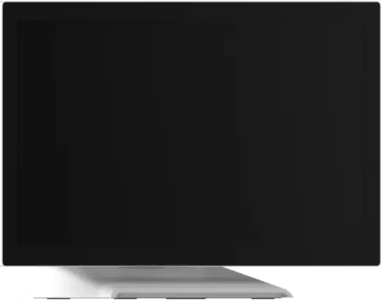
The DT-215P-M1 series is a 21.5” touchscreen monitor that builds to withstand commercial-grade open frame monitor, with stylish thin cable management bracket and versatile design DT-215P-M1 is an exceptional choice for applications for all business sectors and well suited for point-of-sale, point-of-information, point-of-service and interactive signage.
Feature
Cable management bracket design for easy organizing cable.
Specifications
| LCD Touch Panel | |
| Size | 21.5” TFT LCD |
| Brightness | 350 cd/m2 (Non-touch screen) 297 cd/m2 (P-cap touch with AG Coating) |
| Number of Pixels | 1920 (H) × 1080 (V) |
| Touch Type | P-CAP/ 10 points |
| Environment | |
| Certificate | E, CB, FCC, UL, RoHS IEC60601-1-2 4th edition compliant |
| Compliance | Front Panel IP54 |
| Operating Temperature | 0°C ~ 40°C |
| Storage Temperature | -20°C ~ 60°C |
| Operating Humidity | 20% ~ 80% RH, non-condensing |
| Mounting | VESA 100 mm x 100 mm |
| Dimension (W x H x D) | 517.4 mm x 351.7 mm x 219.0 mm |
| Net Weight | 7.8 |
| Gross Weight | 10.8 |
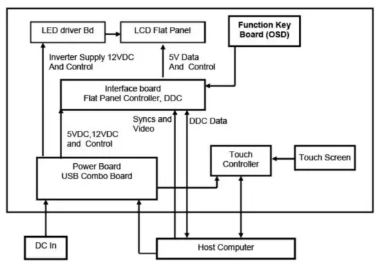
Block Diagram Interface Connectors
 Interface Connectors
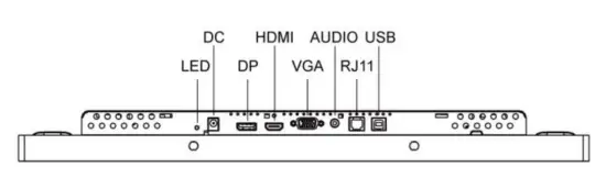
Power Connector
The DC power via external 12V Adapter provide it
Video Signal Connector
|
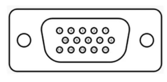
VGA The video signal input via D-type 15-pin female connector. Connector Pin Assignment: | |
| Pin | Signal |
| 1 | RED |
| 2 | GREEN |
| 3 | BLUE |
| 4 | NC |
| 5 | GND |
| 6 | RED_RTN |
| 7 | GREEN_RTN |
| 8 | BLUE_RTN |
| 9 | +5V |
| 10 | GND |
| 11 | NC |
| 12 | SDA |
| 13 | HSYNC |
| 14 | VSYNC |
| 15 | SCL |
|
| |||
| Pin | Signal | Pin | Signal |
| 1 | ML_Lane 0(p) Data0 + | 11 | Signal ground |
| 2 | Signal ground | 12 | ML_Lane 3(n) Data3 – |
| 3 | ML_Lane 0(n) Data0 – | 13 | Signal ground |
| 4 | ML_Lane 1(p) Data1 + | 14 | Signal ground |
| 5 | Signal ground | 15 | AUX_CH(p) AUX + Signal for Auxiliary Channel |
| 6 | ML_Lane 1(n) Data1 – | 16 | Signal ground |
| 7 | ML_Lane 2(p) Data2 + | 17 | AUX_CH(n) AUX – Signal for Auxiliary Channel |
| 8 | Signal ground | 18 | Hot Plug |
| 9 | ML_Lane 2(n) Data 2 – | 19 | DP_PWR Return |
| 10 | ML_Lane 3(p) Data3 + | 20 | DP_PWR |
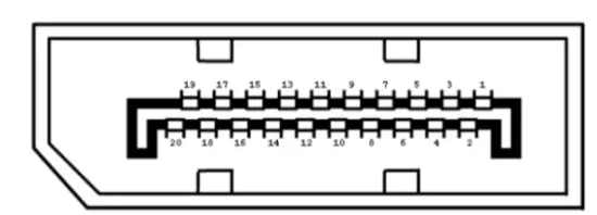 Display Port(1.2a)
|
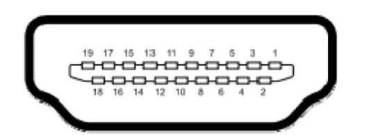
HDMI(1.3) (compatible with HDMI1.4) | |||
| Pin | Signal | Pin | Signal |
| 1 | TMDS Data2+ | 11 | TMDS Clock Shield |
| 2 | TMDS Data2 Shield | 12 | TMDS Clock– |
| 3 | TMDS Data2– | 13 | CEC |
| 4 | TMDS Data1+ | 14 | Reserved (N.C. on device) |
| 5 | TMDS Data1 Shield | 15 | SCL |
| 6 | TMDS Data1– | 16 | SDA |
| 7 | TMDS Data0+ | 17 | DDC/CEC Ground |
| 8 | TMDS Data0 Shield | 18 | +5V Power |
| 9 | TMDS Data0– | 19 | Hot Plug Detect |
| 10 | TMDS Clock+ | ||
Signal Connector
|
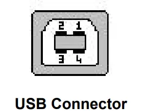
USB Connector | |||
| Pin | Signal | Pin | Signal |
| 1 | VCC | 3 | D+ |
| 2 | D- | 4 | GND |
|
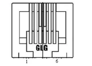
RJ11 Connector (for Remote Key) (option) | |||
| Pin | Signal | Pin | Signal |
| 1 | MENU | 4 | SELECT |
| 2 | UP | 5 | POWER |
| 3 | DOWN | 6 | GND |
|
Line-in Connector | |||
| Pin | Signal | Pin | Signal |
| 1 | GND | 4 | LEFT |
| 2 | LEFT | 5 | RIGHT |
| 3 | RIGHT | ||
Package Overview
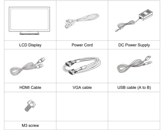
Warming!
This product is intended to be supplied by a Listed Power Adapter or DC power s ource, rated 12Vdc, 4A minimum, Tma = 40 degree C minimum, and the altitude of operation = 3048m minimum. If it needs further assistance with purchasing th e power source, please contact to MicroTouch for further information.
Product Installation
About VESA Mount
The DT-215P-M1 series conform to the “VESA Flat Display Mounting Interface Standard” which defines a physical mounting interface for touch monitor, and corresponding with the standards of touch monitor mounting devices. The VESA mount is located on the back of this unit.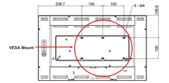
Warming!
Ple ase select the MicroTouch original screws!
The distance between the back cover surface and the bottom of the screw hole is 8 mm. Please use four M4 screws diameter with 8-10mm proper length to mount your monitor.
Note: The mounting stand must be able to support at least 7.67 lbs (3.48 Kg).
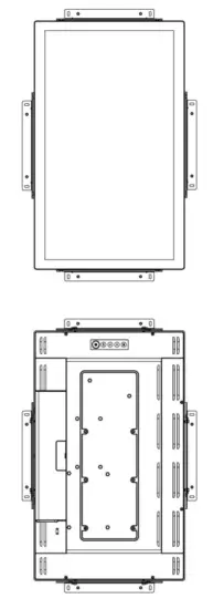
About Wall Mount
The DT-215P-M1 series support wall mount, and this monitor can be mounted to the wooden or concrete wall with 8xM4 screws diameter with 6mm length and two bracket set on the opposites.
Landscape
Depending on your mounting scheme, alternately, you may use the side brackets to mount your displays onto your wall or device.
Find a suitable location for attaching side brackets.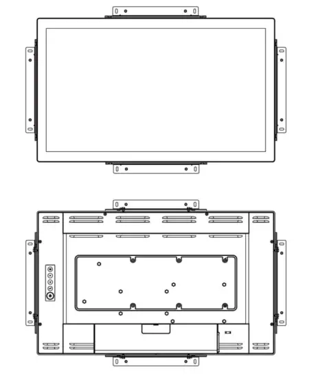
Warming!
This apparatus is intended to be supported by a Listed Wall Mount Bracket” or the equivalent.
Portrait
- A. The left and right sides
- B. The Top and bottom sides

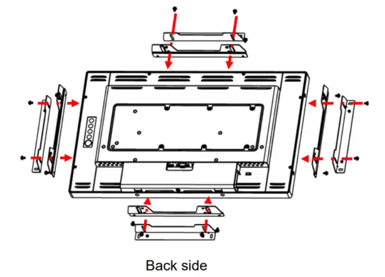
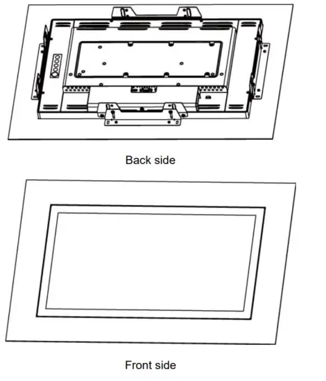
Face up
- Step1: Fixed the 4 x L-bracket on the 4-side of DT-215P-M1

- Step2: Assembly DT-215P-M1 into the wall hole and insert screws.

On-Screen Display 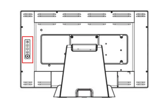
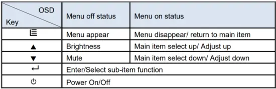
- Press the “MENU” button to pop up the “on-screen menu” and press “Up” or
“Down” button to select among the four functions in the main menu. - Choose the adjustment items by pressing the “SELECT ” button.
- Adjust the value of the adjustment items by pressing the “Up” or “Down” button.
- With the OSD menu on screen, press “ Menu” button to return main menu or exit OSD.
- The OSD menu will automatically close, if you have left it idle for a pre-set time.
- To Lock / Unlock the OSD / Power menu buttons, press “Menu” and “Minus” at the same time to select.
OSD / Power the Lock / Unlock function.
Please note:- When the OSD Lock function is selected, this indicates that all the buttons except “power” button are now disabled.
- When the Power Lock function is selected, this indicates that the power key is disabled; user can not to turn off the monitor by “Power” key.
- To disable the touch function, press “Menu” and “Enter” Key, at the same time.
- To enable the touch function, press “Menu” and “Enter” Key, at the same time for five seconds.
- Press the power key button, there will be an OSD window pop up to ask if it should be going off.
If press the power key in five seconds, the monitor power will be off. If don’t press the power key in five seconds, the OSD window will be gone and return to the normal status instead. - Direct input select function.
- Normal:Press and keep pressing “Select” key for 3 seconds, will change to pop up “source select” OSD.
- Sleep status:Press and keep pressing “Select” key for 1 seconds, will change to pop up “source select” OSD.
- Factory mode: Press the “MENU” button to pop up the “on-screen menu” and select “Option” icon in “Factory” item, key in password “3”,”3″,”3″,”3″ into factory mode.
- Burn-in mode: In Factory mode to select “Burn In” item into Burin-in mode (unplug signal cable or do not enter the signal source).
- Work time: In factory mode, displays monitor the work time counting in hours.
OSD Function Description
| Item | Content | Default |
| Contrast | The monitor luminance level control. | 50 |
| Brightness | The monitor backlight level control. | 100 |
| H-Positon | Moving screen image horizontal position to left or right. | NA |
| V-Positon | Moving screen image vertical position to up or down. | NA |
| Phase | The screen image horizontal dot clock adjustment. | NA |
| Clock | The screen image pixel phase adjustment. | NA |
| Auto Adjust | Fine-tune the image to full screen automatically. | NA |
|
Color Temp | Color temperature selection. (9300K, 6500K, 5500K, 7500K, User) | USER Medical models: R:100,G:93,B:100 Other models: R:100,G:100,B:100 |
| Medical Models: Sharpness | Adjust the screen sharpness. | 50 |
| Medical models: Gamma | Gamma / DICOM function mode. (Native, 1.8, 2.2, DICOM) | Native |
| OSD Timeout | OSD auto-disappear time selection. | 15 |
| Medical models: OSD Positon | Moving OSD menu position. | User |
| OSD H-Positon | Moving OSD menu horizontal position to left or right. | 50 |
| OSD V-Positon | Moving OSD menu vertical position to up or down. | 50 |
| Reset | Factory default value restored. | NA |
| OSD Language | OSD menu language selection. (English, French, Deutsch, Italian, Spanish, Japanese, Traditional Chinese and Simplified Chinese) | English |
| Source Select | Select Input function. (Auto, VGA,HDMI,DP) | Auto |
| Medical models: Display port | Display current resolution related information. | NA |
| Volume | Audio volume adjustment. | 50 |
| Mute | Audio On/Off control. | Off |
| Medical models: Lum Preset | The monitor backlight function quick mode. (Set1, Set2, Set3, User) | User |
| Factory | Factory mode related adjustment items. | NA |
Timing Table Chart
| Mode | Resolution | H-Freq. (KHz) | Band Width (MHz) | Polarity | |
| H | V | ||||
| 1 | VGA 720×400 70Hz | 31.47 | 28.322 | – | + |
| 2 | VGA 640×480 60Hz | 31.47 | 25.175 | – | – |
| 3 | MAC 640×480 66Hz | 35 | 32.24 | – | – |
| 4 | VESA 640×480 72Hz | 37.86 | 31.5 | – | – |
| 5 | VESA 640X480 75Hz | 37.5 | 31.5 | – | – |
| 6 | VESA 800×600 56Hz | 35.16 | 36 | + | + |
| 7 | VESA 800×600 60Hz | 37.88 | 40 | + | + |
| 8 | VESA 800×600 75Hz | 46.88 | 49.5 | + | + |
| 9 | VESA 800×600 72Hz | 48.08 | 50 | + | + |
| 10 | MAC 832×624 75Hz | 49.72 | 57.283 | – | – |
| 11 | VESA 1024×768 60Hz | 48.36 | 65 | – | – |
| 12 | VESA 1024×768 70Hz | 56.48 | 75 | – | – |
| 13 | VESA 1024×768 75Hz | 60.02 | 78.75 | + | + |
| 14 | SXGA 1280×1024 60Hz | 64 | 108 | + | + |
| 15 | SXGA 1280×1024 75Hz | 80 | 135 | + | + |
| 16 | SXGA 1152×864 75Hz | 67.5 | 108 | + | + |
| 17 | SXGA 1280×960 60Hz | 60 | 108 | + | + |
| 18 | WXGA+ 1440×900 60Hz | 56 | 106.5 | – | + |
| 19 | WXGA+ 1440×900 75Hz | 70.6 | 136.75 | – | + |
| 20 | WSXGA+ 1680×1050 60Hz | 65.2 | 146 | – | + |
| 21 | WSXGA+ 1680×1050 75Hz | 82.3 | 187 | – | + |
| 22 | VESA 1280x 768 60Hz | 47.776 | 79.5 | – | + |
| 23 | 1920X1080 60Hz | 67.5 | 148.5 | + | + |
EDID Data
DP/HDMI
The monitor assembly shall provide a display communications channel that conforms to VESA DDC2B hardware requirements. This configuration shall contain the 256-byte EDID file as specified by VESA EDID Standard
VGA
The monitor assembly shall provide a display communications channel that conforms to VESA DDC2B hardware requirements. This configuration shall contain the 128-byte EDID file as specified by VESA EDID Standard
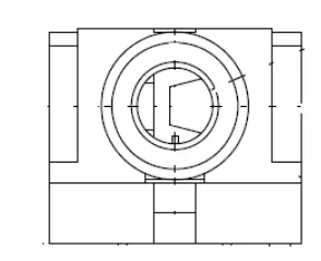
Dimension
Front View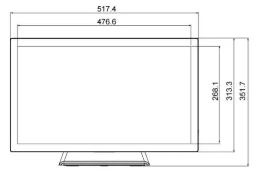 Side View
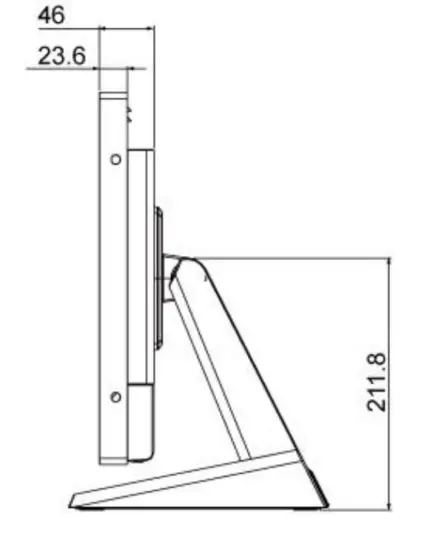
Rear View 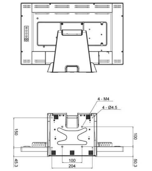


 User Manual")