![]() COD.3.023949 Inail Safety Devices Kit
COD.3.023949 Inail Safety Devices Kit
Instructions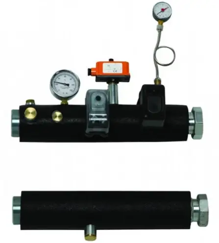
COD.3.023949 Inail Safety Devices Kit
Cod. 1.035610 – Rev. ST.000245/001
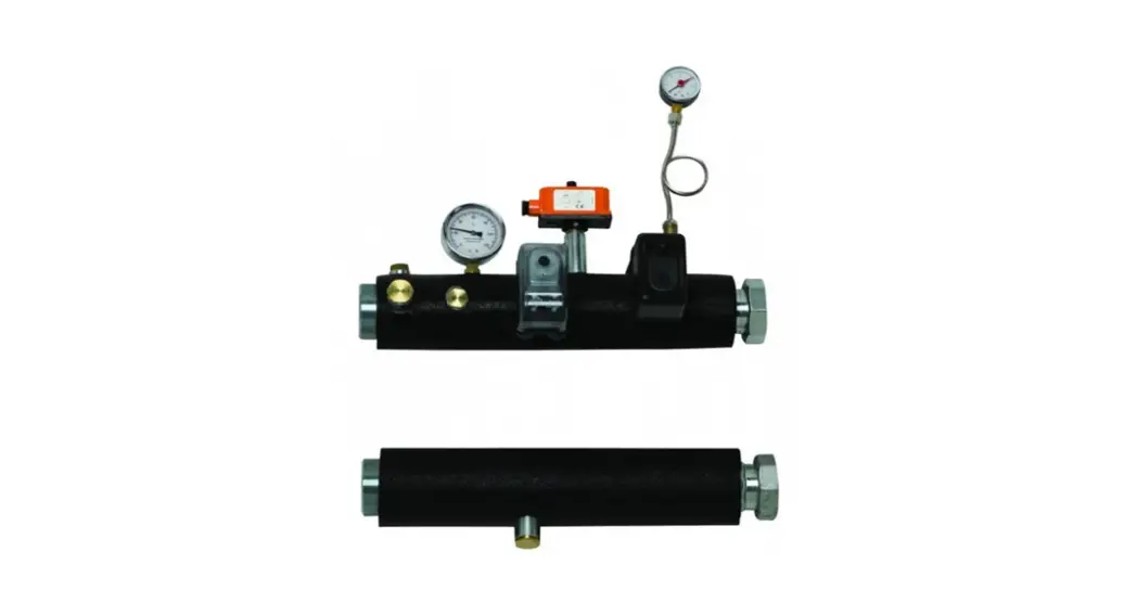
INAIL SAFETY DEVICES KIT
FOR INDIVIDUAL BOILER VICTRIX PRO COD. 3.023949
THIS SHEET MUST BE LEFT WITH THE USER ALONG WITH THE BOILER INSTRUCTION BOOKLET
General warnings.
All products are protected with suitable transport packaging. The material must be stored in dry environments and protected against weathering.
This instruction manual provides technical information for installing the kit. As for the other issues related to kit installation (e.g. safety in the work site, environment protection, injury prevention), it is necessary to comply with the provisions specified in the regulations in force and principles of good practice.
Improper installation or assembly of the appliance and/or components, accessories, kit and devices can cause unexpected problems to people, animals and objects. Read the instructions provided with the product carefully to ensure a proper installation.
Installation and maintenance must be performed in compliance with the regulations in force, according to the manufacturer’s instructions and by authorised professionally qualified staff, intending staff with specific technical skills in the plant sector, as envisioned by the Law.
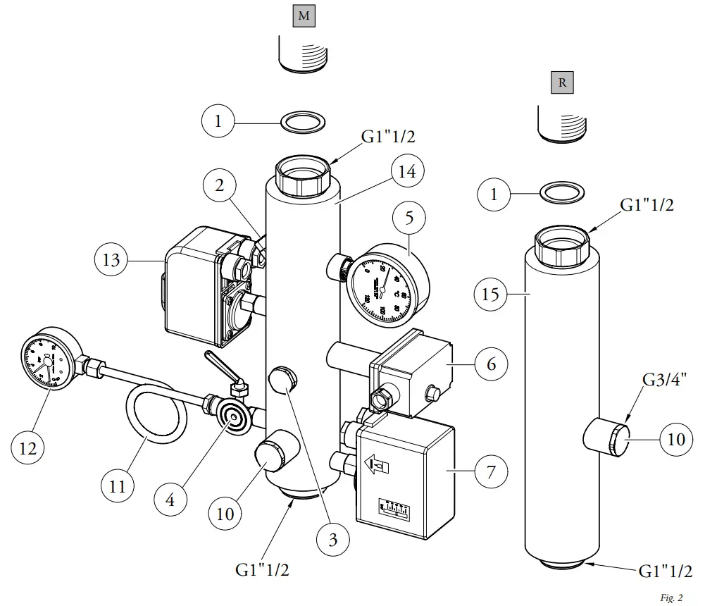
| Ref. | Kit components description | Qty |
| 1 | 44x34x2 gasket | 4 |
| 2 | Thermometer pocket | 1 |
| 3 | Brass plug G1/2″ | 1 |
| 4 | INAIL type-approved manometer-holder cock | 1 |
| 5 | INAIL type-approved thermometer | 1 |
| 6 | INAIL type-approved manual rearm thermostat | 1 |
| 7 | INAIL type-approved manual rearm pressure switch | 1 |
| 10 | Brass plug G3/4″ | 2 |
| 11 | Damper coil | 1 |
| 12 | INAIL type-approved gauge | 1 |
| 13 | INAIL-approved minimum pressure switch | 1 |
| 14 | Insulated supply pin | 1 |
| 15 | Insulated return pin | 1 |
M – System flow
R – System return
Kit Assembly.
Connect the safety kit pins as shown in figure 2, making sure to interpose the gaskets (1).
Connect the wires of the thermostat (6) and the pressure switches (7-13) as shown in figure 3.
Electrical connection.
Make the electrical connection of the pressure switches and the safety thermostat according to the diagram below.
Attention: the boiler has an IPX5D electric insulation rating and can also be installed outdoors, without additional protections. However, if installed outdoors, the relevant piping should be insulated and the kit protected from the elements.
Wiring diagram for the minimum pressure switch kit connection to a single boiler or a set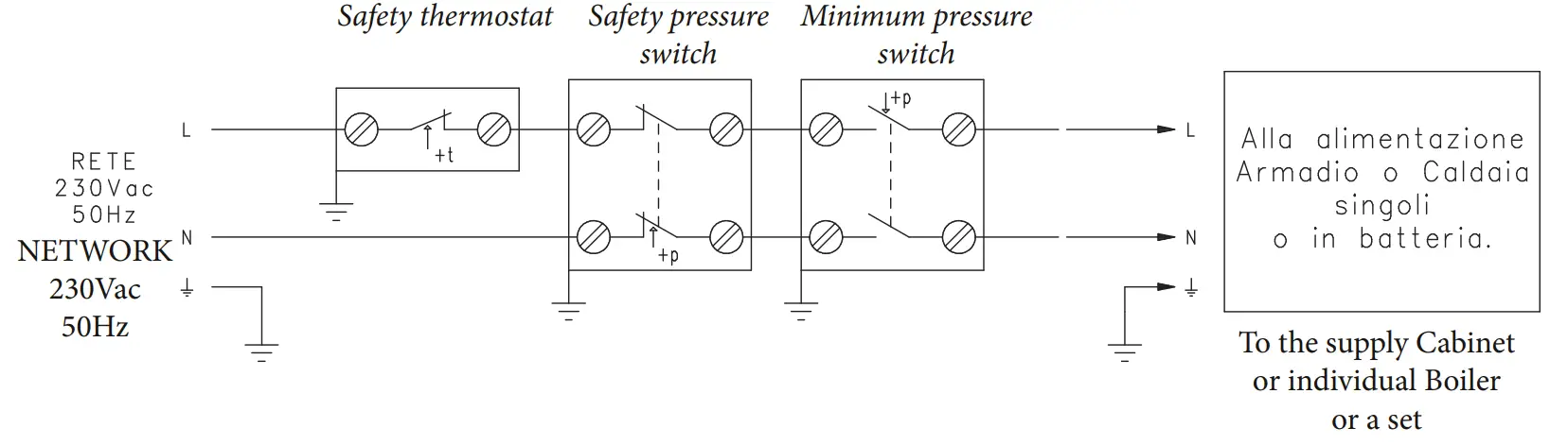
Hydraulic diagram with INAIL safety devices.
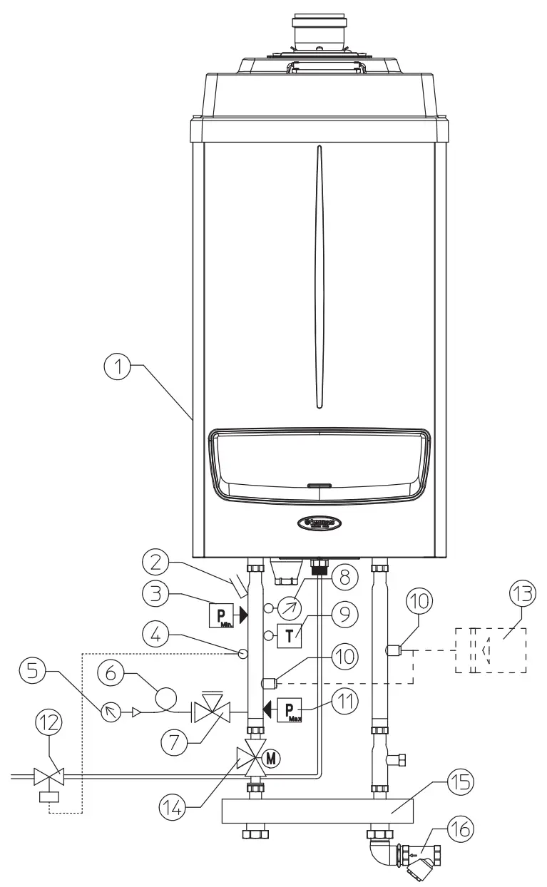
Key:
- Generator
- Manometer pocket
- Minimum pressure switch
- Probe for fuel shut-off valve bulb
- INAIL-approved pressure gauge
- Damper coil
- INAIL-approved pressure gauge-holder cock
- INAIL-approved thermometer
- INAIL-approved manual rearm thermostat
- Attachment for expansion vessel
- INAIL-approved manual rearm pressureswitch
- Fuel shut-off valve
- Expansion vessel
- Boiler connection 3-way valve
- Hydraulic manifold/mixer
- Slurry collection brass filter
N.B.: an adequately-sized system expansion tank (not supplied) should be installed. Also check that the volumes and the pressure drops in the hydraulic circuit do not affect the proper operation of the circulators placed upstream of the expansion tank.
Obligations for the installer.
The boilers must be installed in the configurations and with their own original safety kits.
The factory declines all liability whenever the installer does not use the devices and INAIL-approved original kits or uses them improperly.![]()


