
IMMERGAS 3.023965 Hydraulic Separator Kit
THIS SHEET MUST BE LEFT WITH THE USER ALONG WITH THE BOILER INSTRUCTION BOOKLET
General warnings
All products are protected with suitable transport packaging. The material must be stored in dry environments and protected against weathering. This instruction manual provides technical information for installing the kit. As for the other issues related to kit installation (e.g. safety in the work site, environment protection, injury prevention), it is necessary to comply with the provisions specified in the regulations in force and principles of good practice. Improper installation or assembly of the appliance and/or components, accessories, kit and devices can cause unexpected problems to people, animals and objects. Read the instructions provided with the product carefully to ensure a proper installation. Installation and maintenance must be performed in compliance with the regulations in force, according to the manufacturer’s instructions and by authorised professionally qualified staff, intending staff with specific technical skills in the plant sector, as envisioned by the Law
GENERAL INFORMATION
This kit can be installed with a left or right output and you can decide whether to install the separator on the wall or on a base. The hydraulic separator makes the primary circuit and the secondary circuit independent.
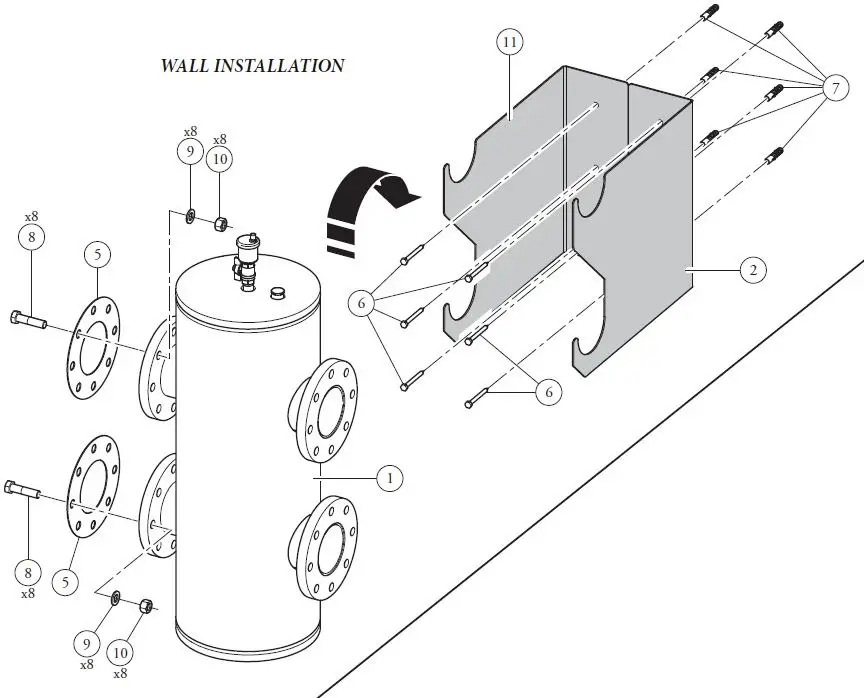
WALL INSTALLATION
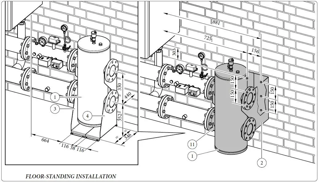
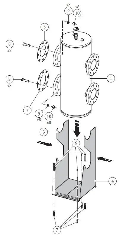
FLOOR-STANDING INSTALLATION
| Ref. | Kit components description | Qty |
| 1 | Hydraulic separator | 1 |
| 2 | Wall-mounted right support bracket | 1 |
| 3 | Separator left support | 1 |
| 4 | Separator right support | 1 |
| 5 | Flange gasket DN100 | 2 |
| 6 | Screws for dowel 8 x 80 | 10 |
| 7 | Nylon dowel 12 x 60 | 10 |
| 8 | Screw M16x65 | 16 |
| 9 | Stainless steel washer 17x30x3 | 16 |
| 10 | Nut M16 | 16 |
| 11 | Wall-mounted left support bracket | 1 |
KIT ASSEMBLY
Proceed as follows to assemble the kit:
Attention: the mounting dimensions shown in figure 1 are indicative and inclusive of the optional ”INAIL Safety devices” kit. For proper installation refer to the relative hydraulic configuration
Wall-mounted installation.
- Make 6 holes Ø 12 using the measurements shown in figure 1 referred to the vertical supports (ref. 2 and 11 fig. 2).
- Insert the 6 dowels (7) in the holes.
- Attach the vertical supports (2) and (11) to the wall with the 6 screws (6) with dowel (7).
- Rest the hydraulic separator (1) on the supports (2) and (11).
- Make the hydraulic connections interposing the relative gaskets (5).
Once the complete kit is installed, check the tighteness of the hydraulic circuit according to that prescribed by the regulations in force.
Base installation.
- Make 4 holes Ø 12 using the measurements shown in figure 1 referred to the supports (3) and (4).
- Insert the 4 dowels (7) in the holes.
- Set the 2 supports (3) and (4) next to each other and fasten them to the floor with the 4 screws (6) with dowel (7).
- Rest the hydraulic separator (1) on the supports (3) and (4).
- Make the hydraulic connections interposing the relative gaskets (5).
Once the complete kit is installed, check the tighteness of the hydraulic circuit according to that prescrived by the regulations in force.
MAIN DIMENSIONS
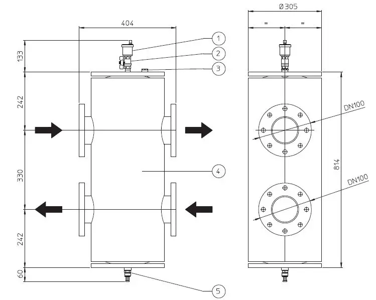
Key:
- Vent valve
- Interception cock
- Attachment for probe (not supplied)
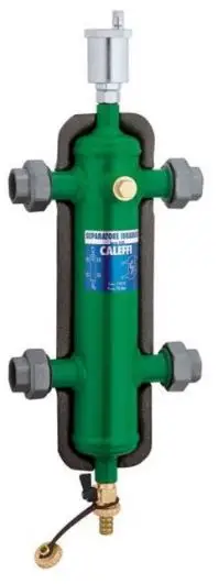
- Hydraulic separator device
- Draining valve


