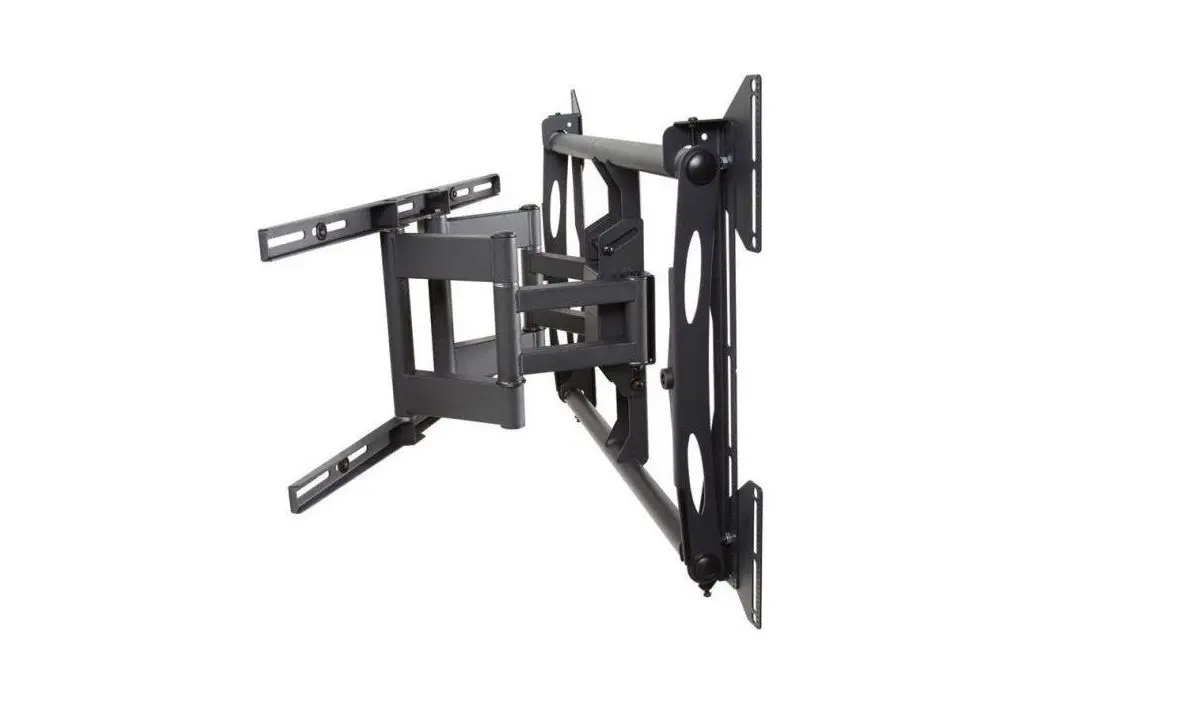
AM175
Installation Guide

![]()

Weight Limit
Maximum Flat Panel Weight: 175 lbs.
THE WALL STRUCTURE MUST BE CAPABLE OF SUPPORTING AT LEAST FOUR TIMES THE WEIGHT OF THE FLAT PANEL. IF NOT, THE WALL STRUCTURE MUST BE REINFORCED.
Warning Statements
 PRIOR TO THE INSTALLATION OF THIS PRODUCT, THE INSTALLATION INSTRUCTIONS MUST BE READ AND COMPLETELY UNDERSTOOD. KEEP THESE INSTALLATION INSTRUCTIONS IN AN EASILY ACCESSIBLE LOCATION FOR FUTURE REFERENCE.
 PROPER INSTALLATION PROCEDURE BY A QUALIFIED SERVICE TECHNICIAN MUST BE FOLLOWED, AS OUTLINED IN THESE INSTALLATION INSTRUCTIONS. FAILURE TO DO SO COULD RESULT IN PROPERTY DAMAGE, SERIOUS PERSONAL INJURY, OR EVEN DEATH.
SAFETY MEASURES MUST BE PRACTICED AT ALL TIMES DURING THE ASSEMBLY OF THIS PRODUCT. USE PROPER SAFETY EQUIPMENT AND TOOLS FOR THE ASSEMBLY PROCEDURE TO PREVENT PERSONAL INJURY.
PREMIER MOUNTS DOES NOT WARRANT AGAINST DAMAGE CAUSED BY THE USE OF ANY PREMIER MOUNTS PRODUCT FOR PURPOSES OTHER THAN THOSE FOR WHICH IT WAS DESIGNED OR DAMAGE CAUSED BY UNAUTHORIZED ATTACHMENTS OR MODIFICATIONS, AND IS NOT RESPONSIBLE FOR ANY DAMAGES, CLAIMS, DEMANDS, SUITS, ACTIONS OR CAUSES OF ACTION OF WHATEVER KIND RESULTING FROM, ARISING OUT OF OR IN ANY MANNER RELATING TO ANY SUCH USE, ATTACHMENTS OR MODIFICATIONS.
 At least two qualified people should perform the assembly procedure. Personal injury and/or property damage can result from dropping or mishandling the flat panel.
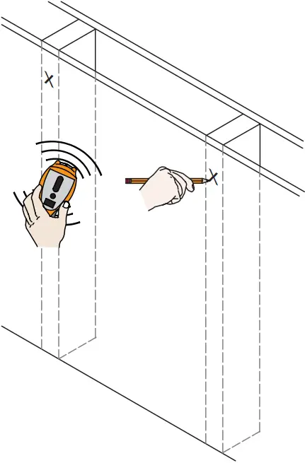
If mounting to wall studs or ceiling studs, make sure that the mounting screws are anchored into the center of the wall studs or ceiling studs. Use of an edge-to-edge stud finder is recommended.
It is recommended that a maximum of 5/8″ plaster board be used when mounting to wooden studs.
 Be aware of the mounting environment. If drilling and/or cutting into the mounting surface, always make sure that there are no electrical wires in wall. Cutting or drilling into an electrical line may cause serious personal injury.
 Make sure there are no water or natural gas lines inside the wall where the mount is to be located. Cutting or drilling into a water or gas line may cause severe property damage or personal injury.
This product is intended for indoor use only. Use of this product outdoors could lead to product failure and/or serious personal injury.
Do not install near sources of high heat. Do not install on a structure that is prone to vibration, movement or chance of impact.
Included components
 x1
x1 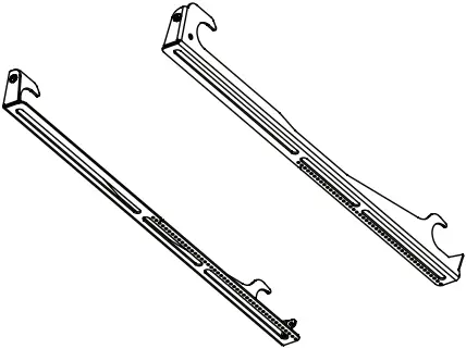 x1 Pair
 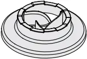 x8
x8
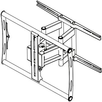
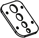
Swingout Mount Mounting Bracket Universal Spacers
 x4
x4 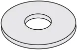 x8
x8 ![]() x4
x4
Griplate™ Washer 5/16″ Flat Washer 5/16″ x 3″ Lag Bolt
![]() x4
x4 ![]() x4
x4 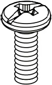 x4
x4
M4 x 16mm M4 x 25mm M4 x 30mm
![]() x4
x4 ![]() x4
x4 ![]() x4
x4
M6 x 16mm M6 x 25mm M6 x 30mm
![]() x4
x4 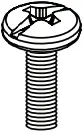 x4
x4 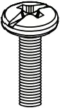 x4
x4
M8x 16mm M8 x 25mm M8 x 30mm
![]() x4
x4  x1
x1 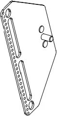 x4
x4
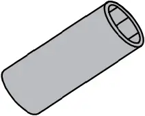
Finned Anchor Thread Depth Indicator (Supplied) Extension Adapter
 x4
x4 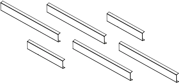 x6
x6
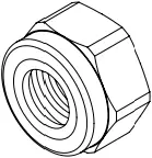
M8 Nylon Nut Channel Covers
Required for installation

Level
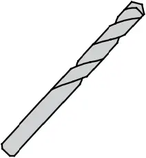
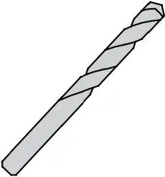
M6 or 1/4″ Wood Drill bit 3/8″ Masonry Drill bit
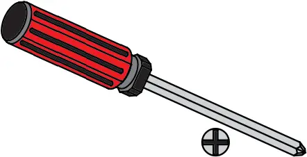
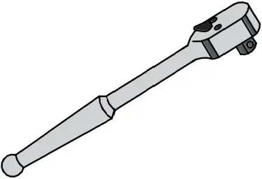
13mm or 1/2″ Socket
Introduction
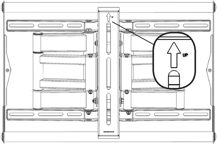
![]() Directional Mounting Arrow
Directional Mounting Arrow
The Directional Mounting Arrow stamped into the AM175 Mount indicates which edge is the top.
Mounting Safety
Two people are recommended for this step
[1]
Wood Installation
Minimum of 2 x 4 wood stud to be used
You must secure the mount to two (2) wall studs with a minimum of four (4) lag bolts (2 lag bolts for each stud found).
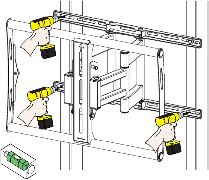
[2]
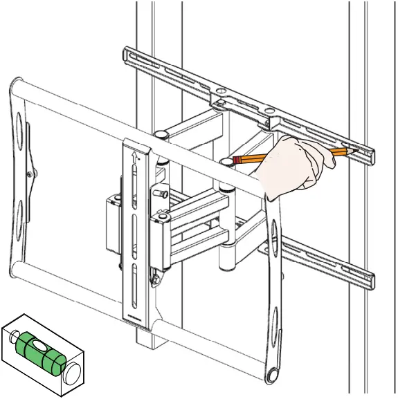
Two people are recommended for this step; one person to level the Mount and another person to mark the wall stud location.
1) Place the mount against the wall in the desired viewing location.
2) Adjust the mount to align the mount slots in the wall plate with the center of the wall studs.
3) Level the mount.
4) Use a pencil to mark the upper right mounting location along the center of the wall stud.
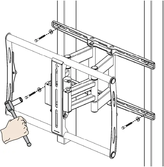
[3]
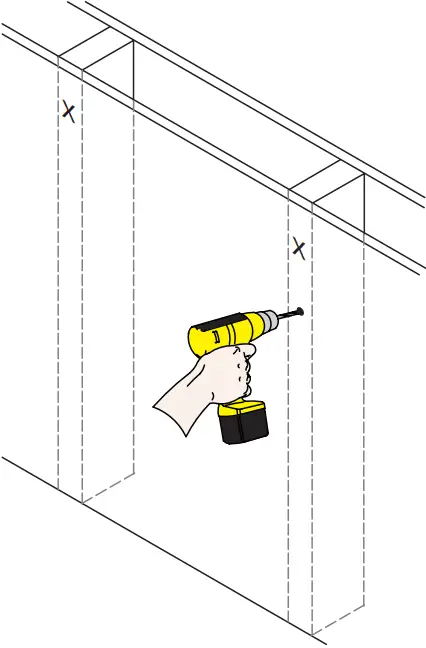
Drill a “pilot hole” in the center of the upper right mark using a 1/4″ drill bit and power drill.
Only use a 1/4″ drill bit when drilling pilot holes.
[4]
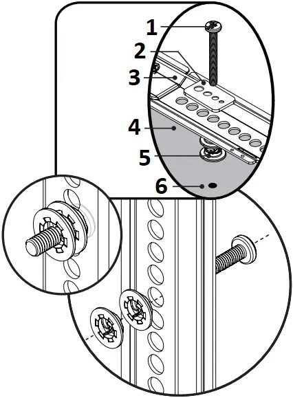
1) Place the Mount against the wall and align it with the pilot hole.
2) Insert one (1) 5/16″x 3 lag bolt and one (1) 5/16″ washer into the upper right pilot hole.
3) Use a socket wrench and a 1/2″ socket to tighten the lag bolt.
Do not overtighten the lag bolt.
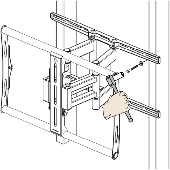
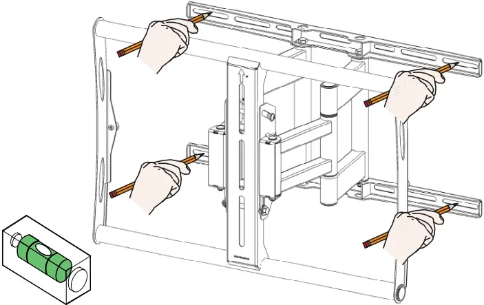
[5]
1) Level the Mount.
2) Use a pencil to mark the remaining three (3) mounting locations along the center of each wall stud.
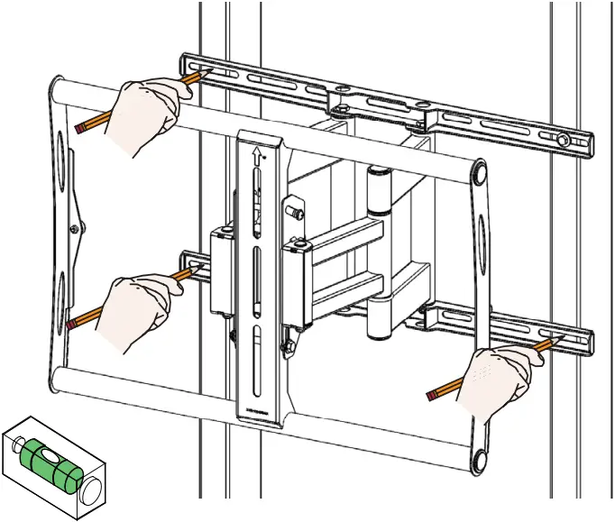
[6]
Two people are recommended for this step; one person to level the Mount and another person to drill the pilot holes.
Drill a “pilot hole” in the center of each of the marks with a power drill and a 1/4″ drill bit.
Only use 1/4″ drill bit when drilling the pilot holes.
[7]
1) Insert one (1) 5/16″ x 3″ lag bolt and one (1) 5/16″ washer into each pilot holes.
2) Tighten all lag bolts using a socket wrench and 1/2″ socket.
Do not overtighten the lag bolts when attaching the mount to the wall. Improper installation may result in personal injury or property damage.
[8]
Concrete Installation
Two people are recommended for this step: one person to level the mount and another person to mark the mounting locations.
[9]
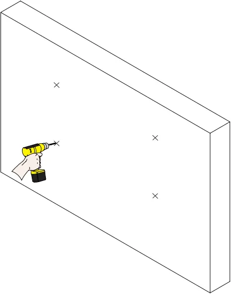
Drill four (4) pilot holes of each mark using a drill and 3/8″ masonary drill bit. Drill 3 inches deep.
Only use a 3/8″ masonary drill bit when drilling pilot holes.
[10]
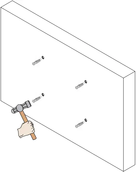
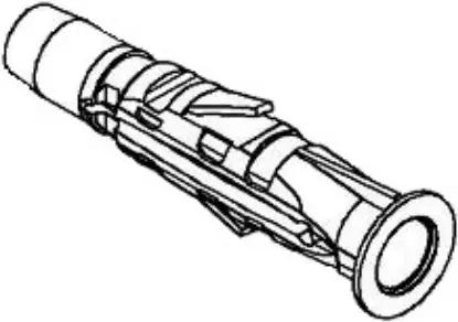
Insert a Finned Anchor into each hole. Lightly tap each Finned Anchors into place with a hammer.
 x4
x4
Finned Anchor
[11]
Insert the lag bolts and washers into the Finned anchors.Tighten all lag bolts using a socket wrench and 1/2 socket.
Do not over tighten the lag bolts.
x4 ![]() x4
x4
5/16″ Flat Washer 5/16″ x 3″ Lag Bolt
Selecting the Mounting Hardware
[12]
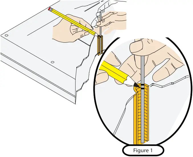
1) Insert a small straw or toothpick into the threaded inserts found on the back of the flat panel.
2) Use a pencil to mark the depth of the threaded insert on the small straw or toothpick.
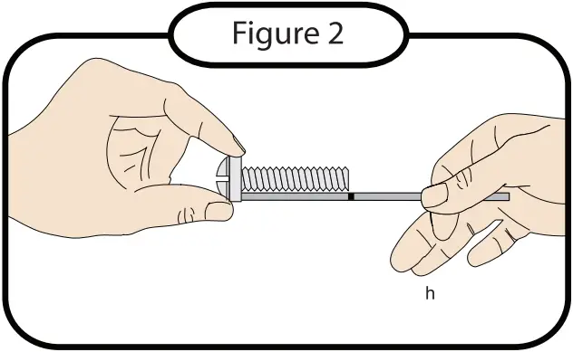
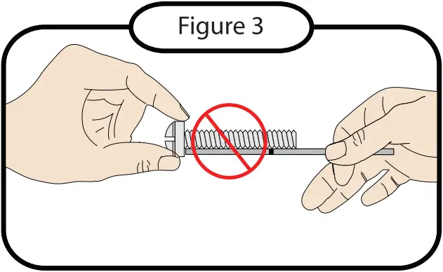
3) Mark the straw or toothpick 1/8″ above the depth of the threaded insert, as shown in Figure 1.
4) Insert the small straw or toothpick into the remaining threaded inserts to compare and verify their depth using the straw or toothpick’s 1/8″ allowance mark.
5) Locate the correct diameter screw for the threaded insert.
If the screw you selected is longer than the 1/8″ allowance mark on the small straw or toothpick, as shown in Figure 2 and Figure 3, do not use this screw. The screw length must not bypass the mark.
6) Test each size of the screws provided.
The correct screws should thread easily into the mounting point and not pull out when tension is applied.
Universal Spacer Installation (Optional)
[13]
- Mounting Screw
- Universal Washer
- Mounting Bracket
- Flat Panel
- Universal Spacer
- Mount Point
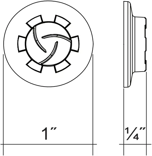
Premier Mounts’ Universal Spacers allow you to attach the mounting bracket to flat-panels which have recessed or uneven mount points. Each Universal Spacer adds 1/4″ to the distance between the mounting bracket and your flatpanel.
The Universal Spacers must be stacked and oriented as shown.
The Universal Spacers must only be installed between the mounting bracket and your flat-panel.
 If your flat panel has uneven mounting points, or recessed mounting points, please use the provided universal spacers.
Universal Washer Installation
[14]
- DIMPLES FACING UP
- DIMPLES FACING DOWN
Premier Mounts’ Universal Washers are designed to accommodate the various M4, M5, M6 and M8 hole sizes required by flat panels.
Do not place excessive pressure on the back of the flat panel, as this may damage your flat panel.
The Universal Washer must be installed between the head of the mounting screw and the mounting bracket as shown.
Mounting Bracket Installation
[15]
- Mounting Hardware
- Mounting Bracket
- Griplate™
- Mounting Point
- Universal Spacer
- Flat
1) Place your flat panel screen-side down on a soft, flat surface.
2) Identify the number and location of the thread inserts on the back of your flat panel.
3) Aligning the holes on each mounting bracket with the thread inserts on the back of your flat panel.
4) Secure each mounting bracket to your flat panel by inserting a minimum of two (2) screws per bracket.
Do not overtighten the mounting hardware.
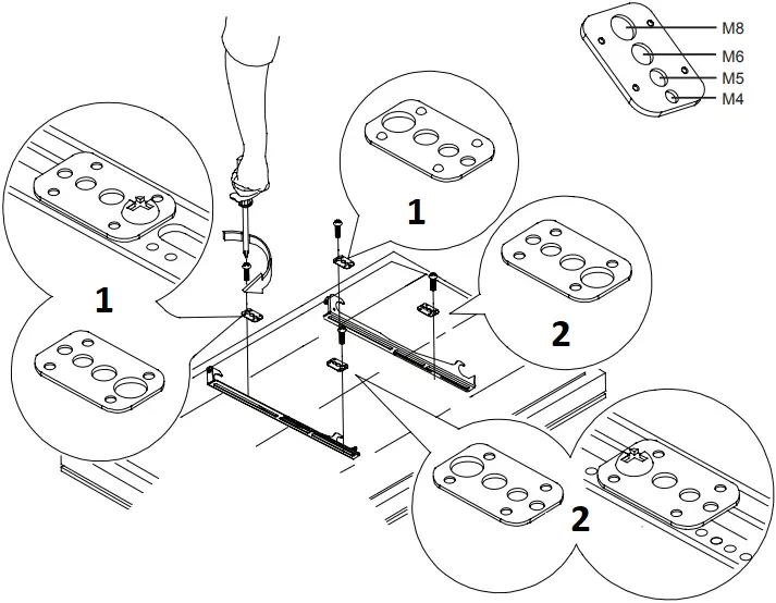
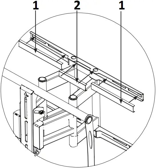
Adapter Plate Installation (Optional)
[16]
The adapter plate can be used with mounting patterns from 200mm x 200mm x to 650mm x 840mm.
In the event that you’re flat panel has recessed or uneven mounting surface, universal spacers may be stacked to achieve proper spacing. Select the amount of universal spacer (s) that is closest in depth to keep your adapter plate as close to the flat panel as possible. The universal spacer must be secured between the flat panel and the adapter plates.
Do NOT over tighten the screws.
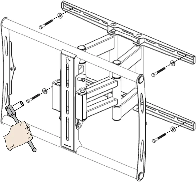
Step 1. Determine if your flat panel will need the adapter plates.
Step 2. Locate the mounting points on the back of the flat panel.
Step 3. Using a screwdriver, insert and tighten the mounting hardware and adapter plates to the back of the flat panel. Do not over tighten the screws.
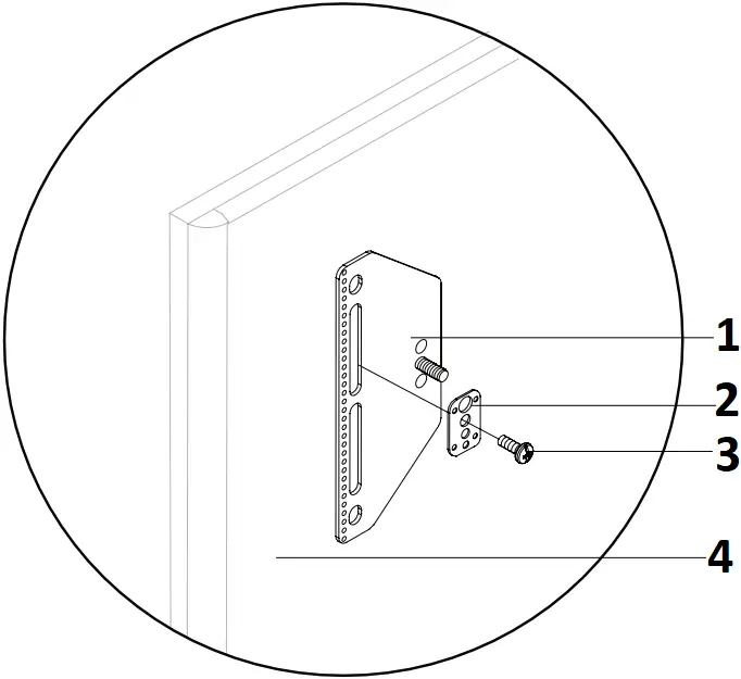
- Adapter Plate
- Griplate
- Mounting Hardware
- Flat Panel
- Adapter Plate
- Socket Wrench
- Nylon Nut
- Flat Washer
- Universal Mounting Bracket
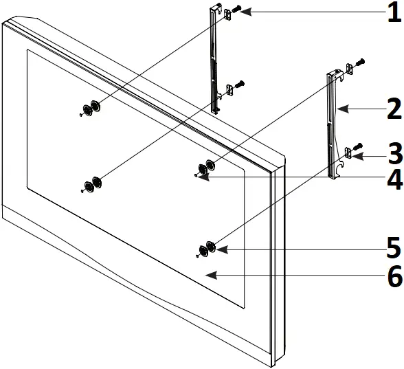
Step 4. Place the universal mounting brackets over the threaded mounting studs that are on the adapter plate.
Step 5. Place one (1) 5 / 16″ flat washer onto each threaded mounting stud.
Step 6. Thread one (1) M8 Nylon nut onto each threaded mounting stud.
Before tightening the nylon nut, be sure that both universal mounting bracket are level and aligned with each other. If they are not aligned and level, the flat panel will not sit properly when mounted to the AM175.
Step 7. Once the universal mounting brackets are level, use a 1/2″ socket and socket wrench to tighten the M8 nylon nuts. Do not over tighten the screws.
Attaching the Flat Panel to the Wall Plate
[17]
 Two people are required for this step.
Do not release the flat panel until verifying the connection between the universal mounting brackets and the upper and lower mounting bars.
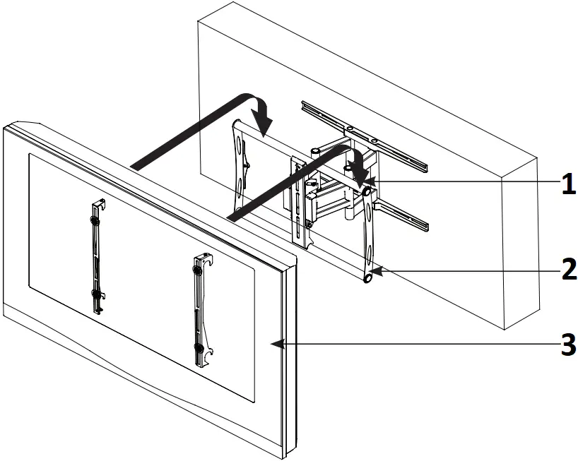
- Upper Mounting Bar
- Lower Mounting Bar
- Flat Panel
Step 1. Place the universal brackets and the flat panel over and onto the upper and lower mounting bars of the AM175 and lower it down. Do not release the flat panel until the flat panel is resting securely on the upper and lower mounting bars.
Securing the Leveling the Flat Panel
[18]
In the event that the flat panel is tilted too far to one side, the leveling screws will allow you to compensate for this tilt by simply adjusting the screws with a screwdriver (see illustration to the right for a clearer view).
Step 1. Use a screwdriver to adjust the two (2) M6 x 30 leveling screws, located on the top of the mounting brackets.
Step 2. Once the flat panel panel is level, ues a screwdriver to tighten the two (2) M6 x 30 locking screws, located on the bottom of the mounting brackets. Do not over tighten these screws.
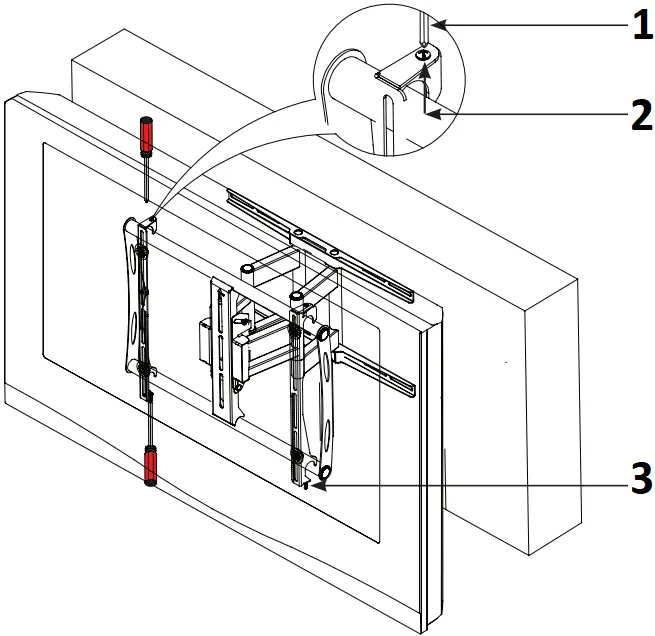
- Screwdriver
- Leveling Screw (Pre-installed)
- Locking Screw (Pre-installed)
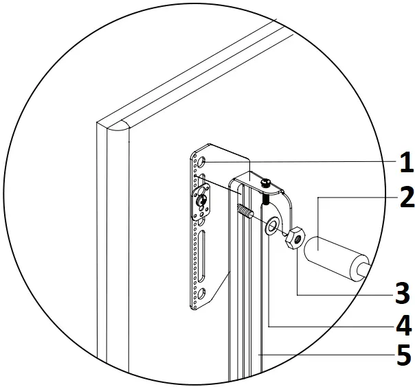
Adjusting the Flat Panel Tilt
[19]
TO ADJUST THE TILT TENSION OF THE AM175, LOOSEN THE TENSION BOLTS LOCATED ON THE BOTTOM RIGHT AND LEFT SIDE OF THE MAIN ARM ASSEMBLY. RE-TIGHTEN THESE BOLTS TO ACHIEVE YOUR DESIRED TENSION.
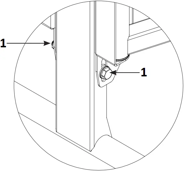
- Tension Bolt
Adjusting the Flat Panel Down
Step 1. Place one hand at the center top edge of the flat panel.
Step 2. Place the other hand on the center bottom edge of the flat panel.
Step 3. Using the upper hand, gently pull the top of the flat panel away from the wall while the lower hand gently pushes the bottom of the flat panel towards the wall.
Adjusting the Flat Panel Down
Step 1. Place one hand at the center top edge of the flat panel.
Step 2. Place the other hand on the center bottom edge of the flat panel.
Step 3. Using the upper hand, gently push the top of the flat panel towards the wall while the lower hand gently pulls the bottom of the flat panel towards the wall.
Plastic Channel Cover Installation
[20]
Step 1. Place the plastic channel covers over the Mounting plate (2 side covers and 1 center cover).
Step 2. Gently push each cover into place, covering the mounting slots of the mounting place.
Repeats steps 1 and 2 for the installation for of the lower plastic channel covers.
- Side Cover (Long)
- Center Cover (Short)
![]()


