![]()
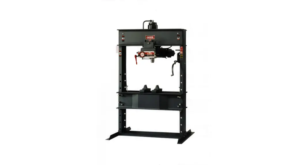
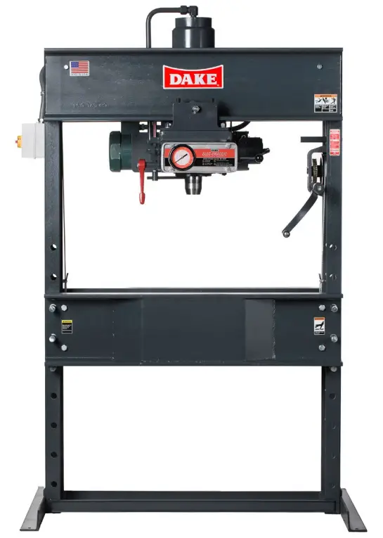
DAKE ELEC-DRAULIC I PRESS
Model 5-150
INSTRUCTIONAL MANUAL
*Model 5-075 shown. There may be slight differences.
5-150 Presses Hydraulic Machine Hub
![]() WARNING!
WARNING!
Read and understand all instructions and responsibilities before operating. Failure to follow safety instructions and labels could result in serious injury.
DAKE STANDARD LIMITED WARRANTY
Finished Machines
Dake warrants to the original purchaser the finished machine manufactured or distributed by it to be free from defects in material and workmanship under normal use and service within 1 year (12 months) from the delivery date to the end user.
Parts
Dake warrants to the original purchaser the component part manufactured or distributed by it to be free from defects in material and workmanship under normal use and service within 30 days from the delivery date to the end user.
The standard limited warranty includes the replacement of the defective component part at no cost to the end user.
Sale of Service (Repairs)
Dake warrants to the original purchaser the component part repaired by Dake Corporation at the manufacturing facility to be free from defects in material and workmanship under normal use and service within 90 days from the return date to the end user, as it pertains to the repair work completed. The standard limited warranty includes repair of the defective component part, at no cost to the end user.
Warranty Process
Subject to the conditions hereinafter set forth, the manufacturer will repair or replace any portion of the product that proves defective in materials or workmanship. The manufacturer retains the sole right and option, after inspection, to determine whether to repair or replace defective equipment, parts or components. The manufacturer will assume ownership of any defective parts replaced under this warranty.
All requested warranty claims must be communicated to the distributor or representative responsible for the sale. Once communication has been initiated, Dake Customer Service must be contacted for approval:
Phone: (800) 937-3253
Email: [email protected]
When contacting Dake, please have the following information readily available:
– Model #
– Serial #
– Sales Order #
Purchasers who notify Dake within the warranty period will be issued a Case number and/or a Return Material Authorization (RMA) number. If the item is to be returned per Dake’s request, the RMA number must be clearly written on the exterior packaging. Any item shipped to Dake without an RMA will not be processed.
Warranty Exceptions:
The following conditions are not applicable to the standard limited warranty:
(a) Part installation or machine service was not completed by a certified professional, and is not in accordance with applicable local codes, ordinances and good trade practices.
(b) Defects or malfunctions resulting from improper installation or failure to operate or maintain the unit in accordance with the printed instructions provided.
(c) Defects or malfunctions resulting from abuse, accident, neglect or damage outside of prepaid freight terms.
(d) Normal maintenance service or preventative maintenance, and the parts used in connection with such service.
(e) Units and parts which have been altered or repaired, other than by the manufacturer or as specifically authorized by the manufacturer.
(f) Alterations made to the machine that were not previously approved by the manufacturer, or that are used for purposes other than the original design of the machine.
RETURN & REFUND POLICY
Thank you for purchasing from Dake! If you are not entirely satisfied with your purchase, we are here to help.
Returns
All Dake manufactured / distributed machines, parts and couplings include a 30-day return option. These policies are valid from the date of final shipment to the end user.
To be eligible for a return, the item must be unused and in the same condition as received.
All requested warranty claims must be communicated to the distributor or representative responsible for the sale. Once communication has been initiated, Dake Customer Service must be contacted for approval:
Phone: (800) 937-3253
Email: [email protected]
Once the return request has been approved by Customer Service, a representative will supply a Return Material Authorization (RMA) number. The returned item must have the provided RMA number clearly marked on the outside packaging. Any item received without an RMA number clearly visible on the packaging will not be processed.
An RMA number can only be provided by the Dake Customer Service team and must be obtained prior to the return shipment.
Refunds
Once the item has been received and inspected for damages, a representative will notify the requestor referencing the provided RMA number.
If the return is approved, a refund will be issued to the original method of payment, less a 20% restocking fee. The restocking fee may be waived if an order is placed at the time of return with like-value merchandise.
Transportation costs are the responsibility of the end user and will not be credited upon return approval.
Any item that is returned after the initial 30 days or has excessive/obvious use will not be considered for a full refund.
SAFEGUARDING THE POINT OF OPERATION
ANSI B11.2 – Hydraulic Power Presses –
Safety Requirements for Construction, Care, and Use
It is important that Dake press users have a clear understanding of their responsibility involving the care and use of their Dake hydraulic press, including point-of-operation safe guards. Dake strongly recommends that Dake press users obtain a copy of the current American National Standard Institute (ANSI) B11.2 standard, for a more complete understanding of their responsibilities.
ANSI B11.2 states the following, relative to point of operation safeguarding:
“Normally, only the employer (press user) can determine the requirements of the press productions system components, including the dies and methods for feeding. Therefore, the employer is ultimately responsible to designate and provide the point-of-operation safeguarding system.”
The standard also discusses additional responsibilities of the employer. Some of the key responsibilities are:
- The employer is responsible for the safety, use, and care of the hydraulic power press production system.
- The employer is responsible to consider the sources of hazards for all tasks to be implemented on the hydraulic power press production system.
- The employer is required to eliminate or control identified hazards in the scope of their work activity.
- The employer is responsible for the training of personnel, caring for, inspecting, maintaining, and operating hydraulic press production systems to ensure their competence.
- The employer is responsible to provide and ensure that point-of-operation safeguarding is used, checked, maintained, and where applicable, adjusted on every production operation performed on a press production system.
A complete and current copy of the ANSI B.11.2 standard can be obtained by contacting the following:
American National Standards Institute
1430 Broadway
New York, NY 10018
AMT – The Association For Manufacturing Technology
7901 Westpark Drive
McLean, VA 22102
SPECIFICATIONS
| Number | 905150 | Ram travel | 16” | |
| Capacity | 150 tons | Horizontal work head travel | 24-3/4” | |
| Horsepower | 2 | |||
| Voltage | 220V/440V 3-Phase | Base | 66” x 42” | |
| Height | 95” | |||
| Width between uprights | 48” | Weight | 3,000 lbs | |
| Width between table channels | 12-1/4” | Ram advance speed | 16 ipm | |
| Pressing speed | 2-3/4 ipm | |||
| Min. ram to table | 10” | RPM | 1,800 | |
| Max. ram to table | 30” | |||
In the space provided record the serial number and model number of the machine. This information is only found on the black and gold Dake tag shown below. If contacting Dake this information must be provided to assist in identifying the specific machine.

| Serial No. | |
| Model No. | |
| Install Date: |
SAFETY
![]() This is the safety alert symbol. When you see this symbol on your press be alert to the potential for personal injury.
This is the safety alert symbol. When you see this symbol on your press be alert to the potential for personal injury.
Employer is responsible to perform a hazard/PPE assessment before work activity.
Follow recommended precautions and safe operating practices.
Additional Warnings:
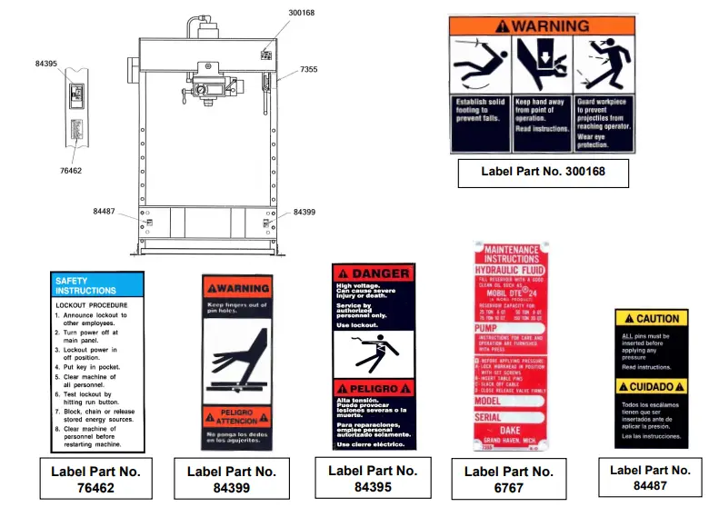
- Carefully read all safety messages in these instructions and on your press safety signs. Keep safety labels in good condition. Replace missing or damaged safety labels.
- Do not alter this press from its original design.
- Do not make repairs or adjustments to any hydraulic system unless you are competent or working under competent supervision.
- Only use Dake original parts.
- This machine is intended to be operated by one person. This person should be conscious of the press ram movement not only for themselves but also for persons in the
immediate area of the machine. - This press is designed for one operator.
- Operator must never place hands in the area of the ram during pressing operations.
- All work requiring the piece to be supported by the operator while being pressed is forbidden.
- Do not use this press for pulling operations.
- It is strictly forbidden to cut, press, or do anything else with pieces whose dimensions or physical nature may explode or produce splinters.
- It is strictly forbidden to tamper with, modify, or elaborate parts of the machine that alter its regular operation.
- A machine not subject to maintenance and periodical structural inspection is a danger for the operator and the persons working nearby.
SET UP
FIRST TIME SET UP
For shipping convenience, the hoist crank was removed from the press and will need to be attached upon arrival.
- The press should be set on a level floor with the base angles touching the floor at all points, using shims where necessary.
- Bolt the press to the floor using four anchor bolts.
- Motor starter box is mounted on left upright. Have an electrician connect power to motor starter. The pump can rotate in either direction.
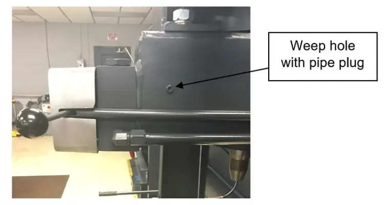
- With the ram up fill the press with oil. Use Mobil DTE oil No. 24 or equivalent. Remove the NPTF pipe plug from the weep hole located on the right side of the reservoir. Start to fill the reservoir using the pour spout at the back of the press. Once oil starts to run out of the weep hole stop filling and replace the pipe plug.
*Filter all oil before adding to press*
Model 5-150 requires 20 quarts of oil.
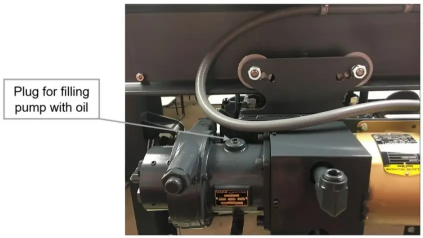
- Prime the pump by removing the plug on the top of the pump and filling it with oil. Wait until the oil levels equalize between the reservoir and the pump, then replace the plug and making sure the seal is tight.

- Attach nose piece to ram by inserting shank into ram and tightening the set screw.
MOVING THE TABLE![]() CAUTION!
CAUTION!
- Place the hoist crank on the lift drum shaft. Turn the hoist crank to relieve the pressure from the table pins. Keeping tension on the hoist crank, remove the table pins one at a time. After removing the table pins, turn the crank that controls the table and run it top to bottom.
- Ensure that the cable is tracking correctly, this means the cable should be on each of the two upper pulleys and should track back and forth on the cable drum.
a. If tracking problems exist, contact the Dake for instructions. - Be sure the table pins are fully inserted in place before applying pressure, servicing, cable tracking, or set up for desired work opening.
![]() Always be sure to put slack into the cable before operating the press.
Always be sure to put slack into the cable before operating the press.
OPERATION
![]() WARNING: DO NOT OVERSTROKE THE RAM. Overstroking will cause premature seal failure.
WARNING: DO NOT OVERSTROKE THE RAM. Overstroking will cause premature seal failure.
Model 5-150 maximum stoke is 16 inches.
- Three set screws (Item 100) are used to lock the workhead in the desired position along the head channels.
- The hand crank (Item 19) is used to raise and lower the table channels to the proper work height. When desired height is reached insert the table pins, three pins on each side.
o Be sure all the table pins are in place and inserted as far as they can go before pressure is applied.
oBe sure to put slack into the cable before pressure is applied. - The handle on the left side of the workhead (Item 67) opens and closes the ball valve, which releases pressure on the ram. This valve should be kept firmly closed, and only opened when it is time to move the ram to its up position.
- The two table plates (Item 6) and two V-blocks (Item 7) are used for supporting the work in process.
- The control handle (Item 86 & 91) on the right side of the panel regulates the speed of ram travel. The handle will return to the off position when released. It is not necessary to stop the motor after each operation.
- The relief valve (Item 79) has been factory set to open when maximum tonnage of the press is reached. The valve should only be adjusted by a professional technician.
oNever exceed the rated tonnage of the press.
MAINTENANCE
LUBRICATION
- Keep all working parts of the press well-oiled for easier operation.
- Keep a light film of oil over the entire surface of the ram to prevent rust.
CHECKING HYDRAULIC OIL LEVEL
Hydraulic oil should be checked and refilled as needed once a week.
*Amount needed may vary dependent on machine use*
To check, open the weep hole, if oil leaks out then the press is still filled properly. If it is not, use step 4 in the “SET UP” section of the manual to add oil.
REPLACING HYDRAULIC OIL
Recommended to replace hydraulic oil every 6 months of machine use.
*Amount needed may vary dependent on machine use*
To empty oil, remove the pipe plug located in front of the ram and use a bucket to catch the old oil. To fill use step 4 in the “SET UP” section of the manual.
Priming the pump is not necessary after replacing oil in the machine.
TROUBLESHOOTING
![]() CAUTION!
CAUTION!
- Use extreme caution when disconnecting any parts of the machine to not introduce any dirt/dust into the hydraulic system, ensure all parts stay clean.
o Filter any oils before adding into the machine. - When performing any maintenance make sure proper lockout procedure is followed.
- High pressure fluid is present in operational hydraulic systems. Fluids under high pressure are dangerous and can cause serious injury or death. Do not make modifications, repairs or adjustments to a hydraulic system unless you are competent or working under competent supervision. If in doubt, consult a qualified technician, engineer, or contact the Dake factory.
1. If the press loses pressure:
a. Check all tubing joins for leaks and tighten tube nuts.
b. Leakage past the release valve (Item 67). Drain reservoir and remove packing nut (Item 66), valve rod (Item 64), and ball valve (Item 63). Clean out valve seat and reseat ball valve using a brass rod as a drift, striking sharply with a hammer. Reassemble valve rod, packing, and packing nut. Refill reservoir with appropriate oil amount.
c. Leakage past eductor inlet check ball (Item 60). Drain reservoir, remove large pipe plug (Item 62), valve seat (Item 61), and check ball (Item 60). Clean and inspect seat. Reset ball on seat or replace seat with new part if necessary. Reassemble with ball above the seat tightening plugs securely.
d. Worn leather cup or T-ring seal. If none of the previous conditions seem to have been the cause, the leather cup or T-ring may be worm or damaged. To inspect, drain oil and remove the work head from the press frame. Remove tube assembly (Item 123). Set two 4×4 blocks on the table then raise the table channels with the block up to the bottom of the reservoir applying pressure to the reservoir. Remove roller brackets from the reservoir and lower the work head using the table.
WARNING: Be sure the stroke indicator rod support is installed in the side of the piston. If not, insert 1/2″-13 stud or cap screw into the tapped hole in the piston. This will hold the piston down under spring pressure.
Next remove nuts from cylinder flange and lift cylinder off piston. The piston leather or T-ring seal can now be inspected and replaced if necessary. Press may be reassembled in reverse order being careful not to damage the lip of the leather cup or T-ring seal as it enters the cylinder.
Note: A leather cup will only be in presses made before 1992 or has a serial number before 192522.
2. Press will not develop rated tonnage.
a. Dirt under ball valves. Refer to 1 – c above.
b. Worn leather cup or T-ring seal. See 1 – d above.
c. Relief valve is not set properly. This valve is located on the top side near the right end of the control block at the front of the reservoir. The valve is set at the factory
to bypass oil from the pump back to the reservoir when the press reaches its rated capacity. The load on the spring (Item 75), which governs the pressure at which the valve will bypass oil, is adjusted by turning the screw (Item 79) in to increase pressure or out to decrease pressure. Replace seal (Item 74) and cap nut (Item 78).
Note: We advise that the relief valve not be tampered with after it is set at the capacity of the press.
3. Nothing happens when press is operated.
a. If motor does not run, the electrical circuit should be investigated.
b. Release valve is open. Be sure to have release valve firmly closed when using press.
c. If the ram will come down only a fraction of its rated stroke, check the oil level in the reservoir with the ram at the top of its stroke.
d. Eductor nozzle is plugged. If motor labors and ram does not move when pump control knob is turned, the orifice in the eductor nozzle (item 73) may be plugged.
Drain reservoir, remove tube assembly (Item 123), eductor bushing (item 70), eductor body (item 72), and eductor nozzle (Item 73). Clean out orifice with a 1/32” drill. Replace parts being sure not to install item 72 backwards. See parts drawing. Check O-ring and back-up washer (items 71A &71B) to be sure it has not been damaged.
4. Press is operating slow.
a. Improper oil. It is essential that the recommended oil (Mobil DTE 24 or equivalent) be used. Heavier oils cause a marked reduction in the ram speed.
Note: DO NOT USE HYDRAULIC JACK OIL.
b. Release valve not closed properly. Release valve must be firmly closed when using the press.
c. The seal on the piston rod for the 50-101 pump is worn. A worn seal will pull air into the pump causing the pump to slowly lose its prime. To test, place grease around the control rod where it goes in and out of the seal (Item 129). Then replace seal part number 26573.
d. The piston rod for the 50-101 pump is bent or rusted. Contact Dake for rebuilding the pump.
Note: Adjustments to the pump are not necessary and the pump should not be tampered with because expensive damage could occur.
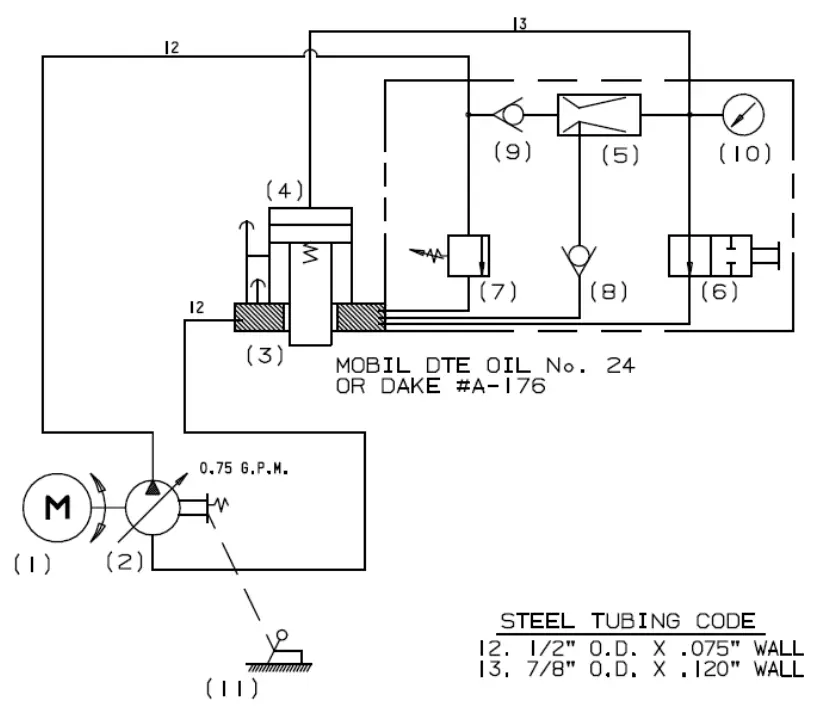
HYDRAULIC DIAGRAM
| 1 | Motor | 2 H.P. | 8 | Intake Check Valve Assem. | ||
| 2 | Pump | 950101 | ||||
| 3 | Reservoir Assembly | 705919 | Ball Valve | 586 | ||
| 4 | Workhead 220V | 905151-2 | Valve Retainer | 1953 | ||
| 4 | Workhead 440V | 905151-4 | 9 | Check Valve Assem | ||
| 5 | Eductor Assembly | Ball Valve | 586 | |||
| Nozzle | 1287 | Spring | 579 | |||
| Eductor Body | 2241 | Seat | 1300 | |||
| 6 | Release Valve Assem. | 10 | Gauge | 71273 | ||
| Ball Valve | 1936 | 11 | Control Rod Assem. | |||
| Release Valve Rod | 2257 | Control Handle | 27433 | |||
| 7 | Relief Valve Assem. | Control Rod | 27669 | |||
| Valve Seat | 6509 | |||||
| Ball Valve | 918 | |||||
| Spring | 893 | |||||
| Adjusting Screw | 2237 | |||||
Sequence of Operation:
- Press Idle – Dake Elec-draulic presses are operated through lever (11) after turning the electric motor switch to “ON”. This lever operated through its range provides ram speeds from zero to the maximum rated pressing speed of the press. This is done entirely within the pump (2) and does not require a variable speed electric motor.
- Advance – When release valve (6) is closed, the fluid flows through the manifold and check valve (9) to the eductor (5). As the oil passes through the restricted orifice of the eductor (5). It “picks up” oil through the check valve (8), giving rapid advance.
- Pressing – When the ram meets resistance, check valve (8) closes and maximum pressure can be built.
- Return – When pressing is completed and lever (11) is returned to zero speed, check valve (9) closes and holds the hydraulic fluid above the ram until it is released back to the reservoir (3) by opening the release valve (6). The ram spring then returns the ram to its up position. In doing this the ram exerts a pressure on the oil and returns it to the reservoir through the open release valve (6).
The relief valve (7) will automatically by-pass the oil back to the reservoir (3) when the oil pressure exceeds system pressure. Check valve (9) holds pressure in the cylinder (4) when relief valve (7) is open. The relief valve (7) is made so the pressure can be reduced to 1/2 its normal operating pressure. By-pass hole in cylinder wall limits travel of ram and protects press from breakage.
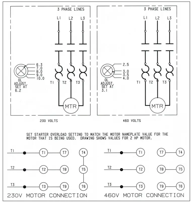
ELECTRICAL DIAGRAMS
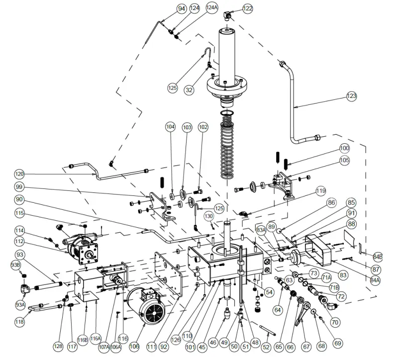
EXPLODED VIEWS & PARTS LISTS
FRAME ASSEMBLY
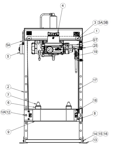
| Item No. | Part Name | Part No. | Qty |
| 1 | Pulley | 1563P | 2 |
| 2 | Frame | 701030P | 1 |
| 3 | Hex Cap Screw (3/4”-10 x 14”) | 43720 | 2 |
| 3A | Lock Washer (3/4”) | 43649 | 2 |
| 3B | Hex Nut (3/4”-10) | 43919 | 2 |
| 4 | Name Plate | 81003 | 1 |
| 5 | Starter Enclosure 220V (Used with 302187 or 302189) | 302062 | 1 |
| 5 | Starter Enclosure 440V (Used with 304090) | 303979 | 1 |
| 5* | Starter/Motor Protection 6.3-10Amp 220V | 302187 | 1 |
| 5* | Starter/Motor Protection 2.5-4.0Amp 440V | 304090 | 1 |
| 5A | Cord Connector | 75151 | 1 |
| 5A | Conduit Locknut | 75257 | 1 |
| 5B | Connector | 41200-01 | 1 |
| 6 | Table Plate | 1534P | 2 |
| 7 | V-Block | 125H-128 | 2 |
| 8 | Table Spacer | 1553P | 4 |
| 9 | Table Channel | 4207P | 2 |
| 12 | Table Pin (Also purchase 77271 & 302816) | 7205P | 6 |
| 12A | Spring Pin | 77271 | 6 |
| 12* | Safety Clip | 302816 | 6 |
| 13 | Base Angle | 1551P | 2 |
| 14 | Hex Head Bolt (5/8”-11 X 1-3/4”) | 43365 | 4 |
| 15 | Lock Washer (5/8”) | 43648 | 4 |
| 16 | Hex Nut (5/8”-11) | 43917 | 4 |
| 17 | Cable | in 700111-S | 1 |
| 18 | Cable Clamp | 583 | 4 |
| 25 | Hex Cap Screw (3/8”-16 x 2-1/2”) | 43353 | 2 |
TABLE HOIST ASSEMBLY
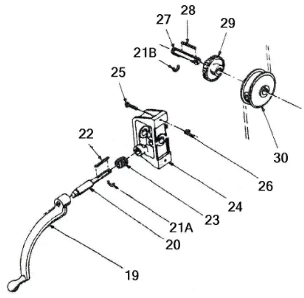
| Item No. | Part Name | Part No. | Qty |
| 19 | Crank Assembly | 701653 | 1 |
| 20 | Worm Shaft | 742 | 1 |
| 21A | Retaining Ring | 43982 | 1 |
| 21B | Retaining Ring | 43983 | 2 |
| 22 | Key | 746 | 1 |
| 23 | Worm | 744 | 1 |
| 24 | Hoist Frame | 739 | 1 |
| 27 | Drum Shaft | 741 | 1 |
| 28 | Drum Key | 745 | 1 |
| 29 | Worm Gear | 743 | 1 |
| 30 | Cable Drum | 740 | 1 |
| – | Cable | 45954 | 19ft |
| – | Table Hoist Assembly (Items 20-30 & Cable) | 700111-S | – |
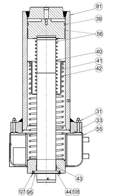
| Item No. | Part Name | Part No. | Qty |
| 31 | Hex Nut (1/2”-13) | 43916 | 4 |
| 33 | Cylinder Gasket | 9778 | 1 |
| 39 | T-Ring (Serial No. > 192523) | 37052 | 1 |
| 40 | Ram Spring – Small | 4196 | 1 |
| 41 | Spring Spacer | 4201 | 1 |
| 42 | Ram Spring – Large | 4195 | 1 |
| 43 | Wear Ring | 37045 | 1 |
| 44 | Oil Seal | 1477 | 1 |
| 55 | Reservoir Assembly | 715273P | 1 |
| 56 | Piston Assembly (Serial No. > 192523) | 716228 | 1 |
| 81 | Cylinder | 4197P | 1 |
| 95 | Retaining Plate/Piston Guide | 6474 | 1 |
| 108 | Oil Seal Gasket | 6519 | 1 |
| 127 | Screw, Machine #10-24 X 1/2” | 43881 | 6 |
| – | Cylinder Repair Kit (Includes Items: 33, 39, 43, 44, 60, 63, 65 71A, 71B, 74, 76 & 108) | 706556 | – |
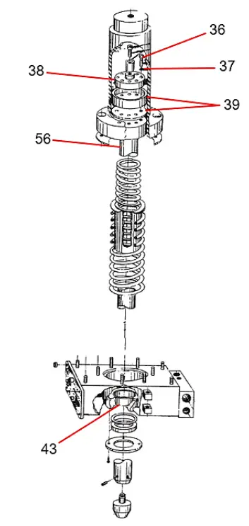
* For presses with serial numbers lower than 192522 or made before 1992 refer to the exploded view and parts list on this page for accurate part information. All other parts that are not listed below are the same for all the 150-ton Elec-draulic I’s and can be found in this manual. *
| Item No. | Part Name | Part No. | Qty |
| 36 | Hex Head Screw (1/4”-20 x 1”) | 43332 | 8 |
| 37 | Lock washer (1/4”) | 43645 | 8 |
| 38 | Supporting Ring | 1536 | 1 |
| 39 | Leather Cup | 1538 | 1 |
| 43 | Piston Bushing | 1158 | 1 |
| 56 | Piston Assembly | 701404 | 1 |
| – | Cylinder Repair Kit (Includes Items: 33, 39, 43, 44, 60, 63, 65 71A, 71B, 74, 76 & 108) | 706556 | – |
EDUCTOR BLOCK ASSEMBLY
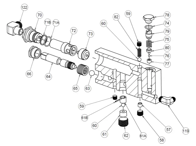
| Item No. | Part Name | Part No. | Qty |
| 57 | Check Valve Seat | 1300P | 1 |
| 59 | Pipe Plug (3/8”) | 588 | 2 |
| 60 | Ball Valve (Ø 1/2”) | 586 | 2 |
| 61 | Relief Valve Seat | 1301P | 1 |
| 61A | Valve Guide | 10752 | 1 |
| 61B | Roll Pin | 44333 | 1 |
| 62 | Socket Head Pipe Plug (1” NPTF) | 44282 | 1 |
| 63 | Ball Valve (Ø 3/4”) | 1936 | 1 |
| 64 | Release Valve Rod | 2257P | 1 |
| 65 | Valve Rod Packing | 1937 | 8 |
| 66 | Packing Nut | 1931P | 1 |
| 70 | Eductor Bushing | 1288P | 1 |
| 71A | O-Ring | 916 | 1 |
| 71B | Back-Up Washer | 11223 | 1 |
| 72 | Eductor Body | 2241P | 1 |
| 73 | Eductor Nozzle | 1287P | 1 |
| 74 | O-Ring | 3965 | 1 |
| 75 | Relief Valve Spring | 893 | 1 |
| 76 | Valve Ball (1/4”) | 918 | 1 |
| 77 | Relief Valve Seat | 891P | 1 |
| 78 | Valve Cap Nut | 2236P | 1 |
| 79 | Relief Valve Adjusting Screw | 2237P | 1 |
| 80 | Ball Retainer | 892P | 1 |
| 82 | Check Valve Spring | 579 | 1 |
| 119 | Fitting, Elbow (1/2 x 3/8 NPTF) | 1252 | 1 |
| 122 | Fitting, Elbow (7/8 x 3/4 NPTF) | 1944 | 1 |
| Item No. | Part Name | Part No. | Qty |
| 32 | Tube Fitting – Compression Elbow (1/4” x 1/8” NPTF) | 19576 | 1 |
| 45 | Set Screw (5/16”) | 43575 | 1 |
| 46 | Nose Piece | 701709P | 1 |
| 48 | Stroke Indicator Rod | 4264P | 1 |
| 49 | Hex Jam Nut (1/2”-13) | 43940 | 1 |
| 50 | Stroke Indicator Rod Nut | 2259P | 1 |
| 51 | Socket Set Screw (1/4”-20 x 1/4”) | 43558 | 1 |
| 52 | Stroke Indicator Support Stud | 4266P | 1 |
| 54 | Stroke Indicator Scale | 4265 | 1 |
| 63 | Ball Valve | 1936 | 1 |
| 64 | Release Valve Rod | 2257P | 1 |
| 65 | Valve Rod Packing Washer | 1937 | 8 |
| 66 | Valve Rod Packing Nut | 1931P | 1 |
| 67 | Release Valve Handle | 2230A | 1 |
| 68 | Spindle Washer | 348 | 1 |
| 69 | Hex Cap Screw (3/8”-16 x 3/4”) | 43324 | 1 |
| 70 | Eductor Valve Bushing | 1288P | 1 |
| 71A | O-Ring (1-1/2” OD x 1-1/4” ID x 1/8”) | 916 | 1 |
| 71B | Back-Up Washer | 11223 | 1 |
| 72 | Eductor Body | 2241P | 1 |
| 73 | Eductor Nozzle | 1287P | 1 |
| 83 | Gauge | 71273 | 1 |
| 83A | Special Gauge Bushing | 81384 | 1 |
| 84A | Control Panel (New Style 4” hole) | 80744 | 1 |
| 84A | Control Panel (Old Style 3-1/2” hole) | 27618 | – |
| 84B | Control Panel Decal | 27620 | 1 |
| 85 | Roll Pin | 28524 | 3 |
| 86 | Control Handle Knob | 27879 | 1 |
| 87 | Machine Screw (#10-24 x 1/4”) | 300248 | 4 |
| 88 | Socket Cap Screw (#10-24 x 3/8”) | 43396 | 3 |
| 89 | Control Handle Mounting Bracket | 27622 | 1 |
| 90 | Control Rod | 27669P | 1 |
| 91 | Control Handle | 27433P | 1 |
| 92 | Washer | 2248 | 4 |
| 93 | Pipe Nipple (3/4” x 8”) | 44205 | 1 |
| 93A | Elbow Pipe Fitting (3/4” NPTF) | 74017 | 1 |
| 93B | Pipe Plug (3/4” NPTF) | 1745 | 1 |
| 94 | Vent Tube (1/4” OD x 20 Gauge Wall) | 6038 | 1 |
| 99 | Rear Roller Bracket | 4204P | 1 |
| 100 | Set Screw (3/4”-10 x 3”) | 43616 | 3 |
| 101 | Screw (3/8”-16 x 1”) | 43328 | 8 |
| 102 | Roller Screw | 1297P | 3 |
| 103 | Flanged Wheel | 2244P | 3 |
| 104 | Ball Bearing | 6023 | 3 |
| 105 | Front Roller Bracket | 4205P | 1 |
| 106 | Motor | 29744 | 1 |
| 106A | Screw (5/16”-18 x 1/2”) | 43313 | 4 |
| 107A | Coupling | 28498 | 1 |
| 110 | Lock Washer (5/16”) | 43644 | 8 |
| 111 | Pump & Motor Base | 27668P | 1 |
| 112 | Hydraulic Piston Pump | 950101 | 1 |
| 114 | Hex Cap Screw (1/2”-13 x 1”) | 43469 | 4 |
| 115 | Pipe Plug (1/2” NPTF) | 589 | 2 |
| 116 | Pump Support | 25916P | 1 |
| 116A | Coupling Cover | 36912M | 1 |
| 116B | Self-Tapping Screw (#10-24 x 3/8”) | 43881 | 3 |
| 117 | Straight Tube Fitting (1/2” x 3/8” NPTF) | 1251 | 1 |
| 118 | Tube Assembly | 705921 | 1 |
| 119 | Tube Fitting – Elbow (1/2” x 3/8” NPTF) | 1252 | 2 |
| 120 | Tube Assembly | 701161 | 1 |
| 122 | Elbow Tube Fitting (7/8” x 3/4” NPTF) | 1944 | 2 |
| 123 | Tube Assembly | 701165 | 1 |
| 124 | Tube Fitting – Compression Straight (1/4” x 1/8” NPTF) | 597 | 1 |
| 124A | Pipe Reducer Bushing | 1100 | 1 |
| 125 | Tubing (1/4” OD x 24 Gauge Wall) | 6038 | 2 |
| 126 | Pipe Plug (1/4” NPTF) | 1567 | 1 |
| 128 | Tube Fitting – Elbow (1/2” x 1/2” NPTF) | 17999 | 1 |
| 130 | Pipe Plug (1/8”) | 589 | 1 |
| – | V-Nose Piece | 701703P | 1 |
| – | Complete Workhead Assembly (Specify Voltage) | 905151-2 905151-4 | – |
Please contact factory for current prices.
ORDERING INFORMATION
Parts are available for direct purchase from Dake or through a distributor. When placing a parts order, you will need to provide the part number, name of part, and model number. All parts shipped F.O.B. Factory in Grand Haven, MI.
INSTRUCTIONS AND PARTS LIST FOR
MODEL 50-101
3/4 GPM Hydraulic Pump
Variable Volume – Step Control
DESCRIPTION
This unit is a five-piston axial type piston pump designed for heavy-duty industrial application up to 6000 psi continuous and 8000 psi intermittent. The pump should be coupled directly to the driving source and can be rotated in either direction.
TYPICAL VARIABLE VOLUME CONTROLS
A) Stem Control – with control stem out (return spring), output delivery is zero gpmpushing in on the control stem increases pump delivery from zero to the maximum gpm.
B) Knob Control – with the control knob adjusted out (counterclockwise rotation), output delivery is zero gpm – turning the control knob clockwise increases pump delivery from zero to the maximum gpm.
C) Pressure Compensated – circuit operating pressure is controlled by setting the compensator valve mounted on the pump. Turning the knob clockwise increases circuit
pressure, counterclockwise decreases circuit pressure. Output delivery of the pump at zero circuit pressure is maximum gpm – when circuit pressure reaches the setting of the
compensator valve pump output automatically decreases to supply the exact flow rate required by the system.
INSTALLATION
- Rotation – Pump shaft rotation can be in either direction.
- Shaft Alignment & Pump Mounting – The alignment of the pump and motor is critical, having a direct relation to pump bearing, shaft seal and coupling life.
- Fluid Connections – Pressure and intake line piping should correspond to port size to keep fluid velocities in an acceptable range. Do not bush down to a smaller size.
- Safety Valves – The high-pressure line must have a relief valve close to the highpressure outlet to prevent damage to the pump. In a circuit using the pressure compensated pump, the relief valve should be set several hundred psi above the compensator pressure to minimize transient pressures due to compensator overtravel.
- Filtration – Cleanliness of fluid and components is of extreme importance in highpressure hydraulic circuits. A suction strainer of 140 microns or less and a twice pump capacity should be used in the pump inlet line.
MAINTENANCE
A) Minor Repairs – Minor repairs are considered those that so not involve total disassembly of the pump. External leaks around the pump, for example, can usually be eliminated by tightening screws and/or fittings around the leakage area. Replacement of leaking shaft or O-ring seals is a minor repair that can be done in the field. The Dake service manual should be consulted for the necessary part numbers.
B) Major Repairs – Major field repairs can be accomplished in an emergency; however, it is recommended that the Dake factory be contacted for necessary assistance. Dake pumps are built to give long-term dependable service. If they should eventually require overhaul, factory rebuilding is recommended when possible since disassembly and assembly can damage many parts. This minimizes replacements with net savings to the user. Trained Dake personnel with complete rebuilding and testing facilities permit rapid overhaul and testing, resulting in minimal downtime for the customer as well as the added advantage of complete factory testing after repair.
| SYMPTOM | CAUSE | SOLUTION |
| Inadequate or no flow from pump | Inlet line is above fluid level | Check fluid level and provide adequate fluid to fill entire system |
| Air in suction pump | Check for loose inlet line connections | |
| Pump not primed | Fill pump cast with Mobil DTE 24 or equivalent and run until pump picks up prime | |
| Broken drive shaft or coupling or loose coupling | Replace broken parts and tighten setscrews in coupling | |
| Oil viscosity is too high | Use proper viscosity fluid for operating temperature conditions | |
| Dirty or clogged oil suction filter | Clean filter and check at least once a month | |
| Broken piston return spring (item NN) or check valve spring (item DD) | Replace broken parts and reassemble | |
| Pump till not build pressure | Loose check valve seat retainers (items BB) | Retighten loose parts, use thread-locker when retightening |
| System relief valve stuck open | Check valve for contamination | |
| Pump is running hot | System relief valve constantly spilling | Check relief valve setting and work cycle |
| Duty cycle excessively at high pressure | Install oil cooler on fluid reservoir | |
| Noisy pump or system | Air in system | Bleed all circuit trapped areas |
| Pump cavitation | Check for restriction in pump inlet or for loose fittings in inlet line | |
| Coupling misaligned | Realign couplings | |
| Broken piston return spring (item NN) | Replace broken parts and reassemble | |
| Loose piston shoe (item L) | Replace with new parts (items L & M) | |
| Pump will not prime or loses prime | Loose cylinder locking screws (items W) | Tighten screws |
| Worn or damaged shaft seals (items C or AC) | Replace with new parts | |
| Faulty O-ring (items V, MM, TT, or AB) | Replace with new parts | |
| Air in suction | Check for loose fittings and tighten |
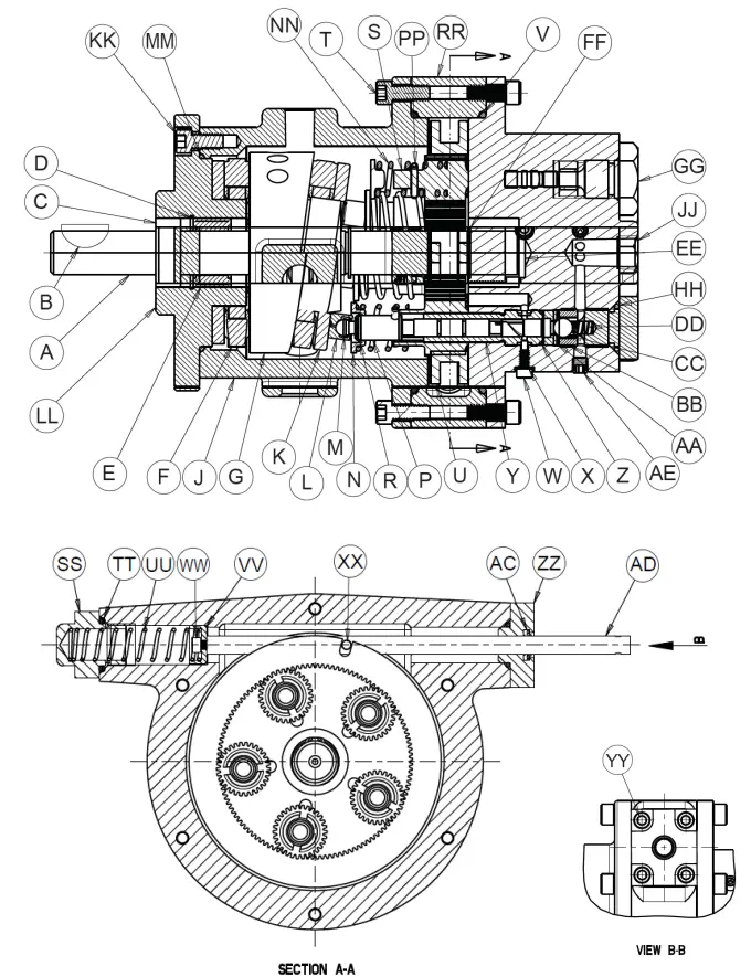
| Item No. | Part Name | Part No. | Qty |
| A | Pump Shaft | 25110 | 1 |
| B | Woodruff Key 608 | 300449 | 2 |
| C | Oil Seal | 26184 | 2 |
| D | Retaining Ring – Truarc | 27468 | 1 |
| E | McGill Roller Bearing MR-14 | 26186 | 2 |
| F | Rollway Thrust Bearing T618 | 26185 | 1 |
| G | Wobble Plate | 25200 | 1 |
| J | Pump Body | 25109 | 1 |
| K | Rollway Thrust Bearing T619 | 26187 | 1 |
| L | Piston Shoe | 25117A | 5 |
| M | National Retaining Ring | 26188 | 5 |
| N | Spring Retainer | 25116A | 5 |
| P | Piston | 25114 | 5 |
| R | National Retaining Ring | 27751 | 5 |
| S | Piston Rotating Gear | 25115 | 5 |
| T | Socket Head Cap Screw (5/16”-18 x 3/4”) | 43433 | 12 |
| U | Control Gear | 25120 | 1 |
| V | O-Ring (5-3/8” ID x 5-5/8” OD) | 26183 | 2 |
| W | Cylinder Locking Screw | 25121 | 5 |
| X | Metallic Screw | 26629 | 5 |
| Y | Cylinder | 25113 | 5 |
| Z | O-Ring (9/16” ID x 11/16”) | 26564 | 5 |
| AA | Valve Seat | 25122A | 5 |
| BB | Seat Retainer | 25123A | 5 |
| CC | Check Valve Ball | 1222 | 5 |
| DD | Check Valve Spring | 25126 | 5 |
| EE | Thrust Washer | 27439 | 1 |
| FF | Truarc Retaining Ring | 27437 | 2 |
| GG | Pump End Cap | 25124 | 5 |
| HH | O-Ring (3/4” ID x 15/16” OD) | 3966 | 5 |
| JJ | Pump Head | 25111 | 1 |
| KK | Socket Head Cap Screw (5/16”-18 x 5/8”) | 43432 | 6 |
| LL | Flange | 27424 | 1 |
| MM | O-Ring (3-3/4” ID x 3-15/16”) | 27438 | 1 |
| NN | Piston Spring | 25119 | 5 |
| PP | Spiral Pin (1/8” x 7/8”) | 28688 | 5 |
| RR | Center Pump Body | 26181 | 1 |
| SS | Control End Cap | 27440 | 1 |
| TT | O-Ring (7/8” ID x 1-1/8”) | 3965 | 1 |
| UU | Spring | 27441 | 1 |
| VV | Control Rod End Spacer | 25132 | 1 |
| WW | Socket Head Cap Screw (10-24 x 3/8”) | 43397 | 1 |
| XX | Control Pin | 25131 | 1 |
| YY | Socket Head Cap Screw (1/4”-20 x 1/2”) | 43412 | 4 |
| ZZ | End Cap | 25129 | 1 |
| AB | O-Ring (3/4” ID x 15/16”) | 3966 | 1 |
| AC | Oil Seal | 26573 | 1 |
| AD | Control Rob | 25912 | 1 |
| AE | Pipe Plug (1/16” NPTF) | 44276 | 5 |
| – | Label | 26190 | 1 |
| – | Drive Screws for Label | 43573 | 2 |
| Pump Repair Kit – Includes Items: B, C, V, Z, HH, MM, TT, AC, & AD | 712740 | – | |
DAKE STANDARD TERMS & CONDITIONS OF SALE
All proposals and quotations for the original sale of our products are subject to the following terms and conditions:
ACCEPTANCE OF ORDER: All orders are subject to acceptance by Dake at its main office in Grand Haven, Michigan.
APPLICABLE LAWS: This quotation or acceptance shall be governed in all respects by the laws of the State of Michigan.
CANCELLATION: We reserve the right to cancel and/or refuse to complete your order if, in our opinion, you have not established credit to promptly meet the payment terms of your order. Any cancellation from the Purchaser may be subject to a 10% cancellation fee for any of our non-standard machinery upon the discretion of Dake. All custom or special quotes will not be eligible for cancellation, nor returns.
DELIVERY: The proposed shipment date is an estimate and is contingent upon causes beyond Dake’s control. Under no circumstances shall Dake have any liability for loss of use or for any direct or consequential damages resulting from delay. All shipments from the Dake facilities are F.O.B.
FREIGHT CLAIM: Damage freight claims must be submitted to Dake within thirty (30) days of shipment from Dake’s facility. If shipment for order was set up by the Purchaser, Dake is not liable to handle the freight claims.
PERMITS AND COMPLIANCE: Dake shall not be responsible for obtaining any permits, inspections, certifications, or licenses required for the installation or use of the equipment. Dake makes no promise or representation that the equipment or any services to be furnished by Dake will conform to any federal, state, or local laws, ordinances, regulations, codes or standards.
PRICES: Unless otherwise agreed to in writing, all prices are F.O.B. our plant in Grand Haven, Michigan and Grand Prairie, Texas. In any event, the quoted prices for component parts become invalid ten (10) days after date of quotation, and machinery may become invalid sixty (60) days after date of quotation. Unless otherwise specified in Dake’s quotation, installation services and final on-site adjustments are not included in the quotation.
TAXES: Prices do not include taxes. If any sales, use or similar tax is payable to Dake in connection with any transaction or part thereof between the Purchaser and Dake with respect to goods delivered, the Purchaser will, upon demand, pay to Dake the amount of any such tax. If you are tax exempt, please include your exemption document when submitting your order.
TERMS OF PAYMENT: Terms of payment are as stated in Dake’s quotation subject to credit approval by our home office. Dake will invoice Purchaser when the equipment is completed and ready for shipment. Payment terms run from invoice date. Purchaser may be required to issue a down payment before production of order and shipment, at the discretion of Dake Accounting. For credit card purchases, a 2% processing fee may be applicable to the order. The following states are exempt from the 2% processing fee: CA, CO, KS, OK, TX, FL, NY, CT, MA, and ME. Dake’s preferred method of payment is as follows: ACH Wire and credit card. Checks will be accepted but may cause delay in order processing. Below is our billing address:
1809 Industrial Park Drive, Grand Haven, MI 49417
WARRANTY If, within a period of one (1) year from date of shipment, any part of any equipment sold by Dake is defective in material or workmanship and is so found after inspection by Dake, it will be replaced or repaired at the option of Dake, providing the equipment has been given normal and proper usage and is still the property of the original Purchaser. Purchased components such as Micro Drop mist system or the like, installed as a part of Dake equipment are warranted only to the extent of the original Manufacturer’s warranty. Dake is not responsible for any service work performed unless authorized in advance.
THE FOREGOING WARRANTY IS EXCLUSIVE AND IN LIEU OF ALL OTHER WARRANTIES WHETHER WRITTEN, ORAL OR IMPLIED (INCLUDING ANY WARRANTY OF MERCHANTABILITY OR FITNESS FOR PARTICULAR PURPOSE). UNDER NO CIRCUMSTANCES SHALL DAKE BE LIABLE FOR ANY INCIDENTAL OR CONSEQUENTIAL DAMAGES.
Dake Corporation
1809 Industrial Park Drive
Grand Haven, MI 49417
Tel (800) 937-3253
www.dakecorp.com
[email protected]
[email protected]


