![]()
![]()
 WARNING: Read these instructions before using the machine
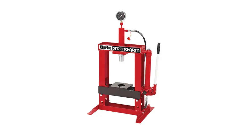
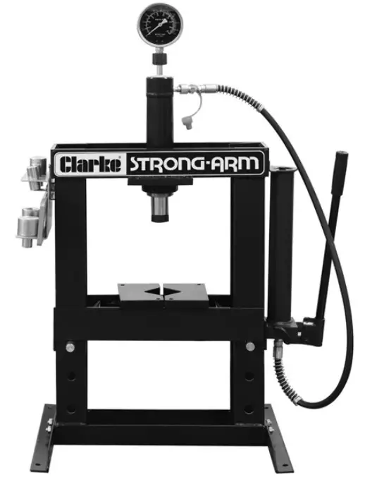
10-TONNE HYDRAULIC BENCH PRESS
MODEL NO: CSA10BB
PART NO: 7614020
OPERATION & MAINTENANCE INSTRUCTIONS

DL0822
INTRODUCTION
Thank you for purchasing this CLARKE 10 Tonne Hydraulic Bench Press.
Before attempting to operate the machine, it is essential that you read this manual thoroughly and carefully follow all instructions given. In doing so you will ensure the safety of yourself and that of others around you, and you can also look forward to the press giving you long and satisfactory service.
GUARANTEE
This CLARKE product is guaranteed against faulty manufacture for a period of 12 months from the date of purchase. Please keep your receipt as proof of purchase.
This guarantee is invalid if the product is found to have been abused or tampered with in any way, or not used for the purpose for which it was intended. Faulty goods should be returned to their place of purchase, no product can be returned to us without prior permission. This guarantee does not affect your statutory rights.
TECHNICAL SPECIFICATIONS
| Capacity | 10 tonne |
| Operating pressure | 10000psi |
| Ram stroke | 184mm |
| Ram diameter | 42mm |
| Net weight | 55kg |
| Dimensions | 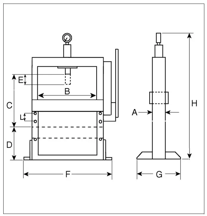 |
| A)110mm | |
| B)340mm | |
| C)365mm | |
| D)180mm | |
| E)183mm | |
| F)600mm | |
| G)450mm | |
| H)1070mm | |
| L) 80mm |
SAFETY PRECAUTIONS
- During assembly or if the press is moved, always call for the help of an assistant, DO NOT manhandle single-handedly.
- ALWAYS bolt the press down to a suitably strong bench.
- Ensure the press is located on a strong bench with adequate light.
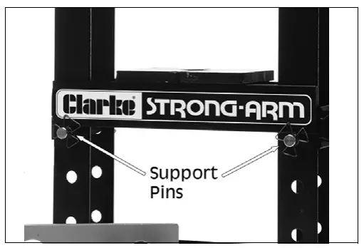
- Before applying a load, ensure all press bed support pins are fully engaged.
- Ensure that hydraulic hoses and couplings are completely sound.
- Before use, ALWAYS ensure the workpiece is firmly secure and stable.
- ALWAYS clean spills of hydraulic oil immediately as this can be dangerous in a workshop environment.
- DO NOT exceed the rated capacity of the press.
- DO NOT allow any person who is inexperienced in the use of hydraulic presses, to use the press unless they are under direct supervision.
- DO NOT allow anyone to work directly in front of the press when it is in use.
- NEVER tamper with the press. The safety valve is calibrated and sealed at the factory; DO NOT attempt to change the setting.
- Use only the recommended hydraulic oil.
- The components of this press are specially designed to withstand the rated capacity. DO NOT substitute bolts, pins, or any other components
- ALWAYS apply the load under the center of the ram. Offset loads can damage the ram or ram mount and may cause the workpiece to eject.
- Before operating, check for signs of cracked welds, bent bed pins, loose or missing bolts, or any other structural damage. DO NOT operate if any of these conditions exist. Have repairs made only by an authorized service center.
- Remove load from press bed before attempting to adjust bed height.
- Press only on a workpiece supported by the press bed.
- When using accessories such as arbor plates, be certain they are centered below the ram and are in full contact with the bed.
- Parts being pressed may splinter, shatter, or be ejected from the press. Due to varied applications, it is your responsibility to always use adequate guards, and wear eye protection and protective clothing when operating this press.
- Keep hands and fingers away from parts that may pinch and shift.
- DO NOT use extension tubes on the pump handle. Excessive effort can cause damage and/or accidents.
UNPACKING
Ensure the press and its components suffered no damage during transit and that all components are present. Should any loss or damage become apparent, please contact your CLARKE dealer immediately.
TOOLS REQUIRED
- Spanners to suit M6, M8 and M10 nuts/bolts, or an adjustable wrench.
- PTFE tape
ACCESSORIES
A mandrel set (including storage bracket and pressure plate) is not supplied with the press but is available from your dealer as Clarke part no 7615060.
INVENTORY
| 1 x Frame | 1 x Pump |
| 2 x Base Supports | 1 x Pump Handle |
| 1 x Ram with Locking Collar | 1 x Hose (attached to pump) |
| 1 x Pressure Gauge | 1 x Press Bed (Frame) |
| 2 x Bed Support Pins | 2 x Bed blocks (V-blocks) |
| 1 x Fixing Kit containing bolts, washers & nuts | |
ASSEMBLY
IMPORTANT: Due to the weight of the press components, we recommend that you get assistance during installation.
IMPORTANT: We strongly recommend that the press be firmly secured to a firm and level bench using suitable bolts (not supplied).
IMPORTANT: Do not locate your press where it will be open to the elements, Severe weather conditions will damage the hydraulic components.
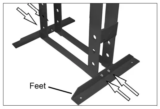
- Attach the feet to the frame, using the nuts, bolts, and washers.
- With the help of an assistant, lift the frame assembly upright and maneuver it to its intended location on the workbench.
• It is strongly recommended that the press be firmly secured to a firm and level bench using suitable bolts (not supplied)
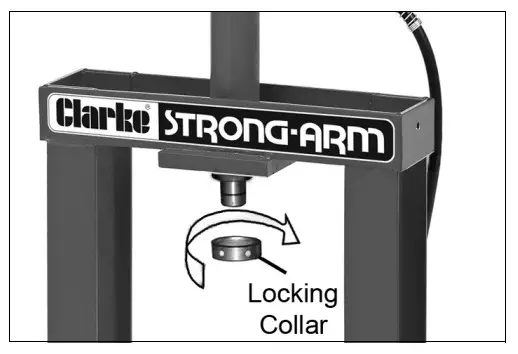
- Insert the ram through the hole in the base plate and secure in position using the locking collar.

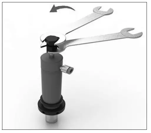
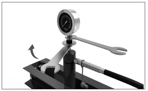
- Using two spanners, unscrew the transportation cap from the top of the press cylinder as shown.

- Remove the cap and ball bearing as shown.

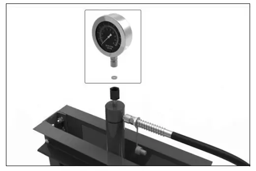
- Place the washer and pressure gauge in the top of the press cylinder

- Making sure the gauge faces the front of the press, using two spanners, tighten the gauge nuts as shown.

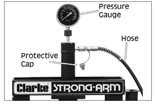
- Unfasten the protective end cap and screw the hose to the threaded connection of the hydraulic ram.
• We recommend sealing the thread with PTFE tape. Take care not to let any oil escape while connecting the hose.
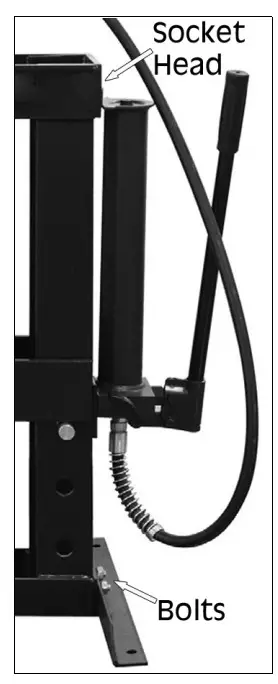
- Attach the pump assembly to the frame using the fixing bolts and washers. Fit one bolt first to bear the weight and use the adjustment provided by the upper bolt.
• The pump can be installed on either side of the frame but will usually be assembled for a right-handed press operator. - Screw the pump handle into the pump actuating lever.

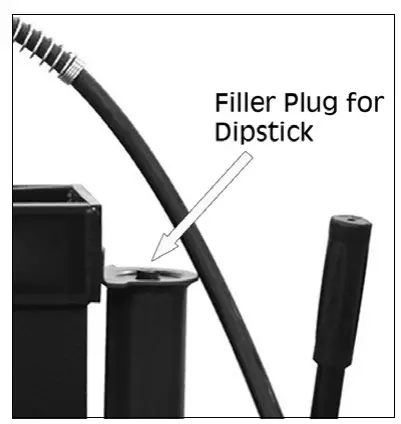
- Unscrew the filler plug and withdraw the dipstick. Check that the pump is filled with hydraulic oil up to the level shown on the dipstick.
• If empty, the total capacity is 630ml.
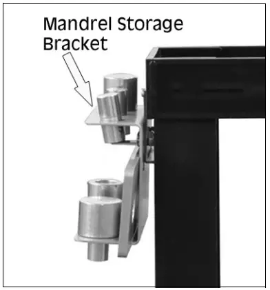
- If obtained, bolt the mandrel storage bracket to the side of the frame using the bolts supplied.
- Store the mandrels including the adaptor, in their positions on the bracket.

- Insert the bed support pins into the holes in the columns at the required position. Then set the bed frame in position on the pins.

HYDRAULIC PUMP/RAM OPERATION
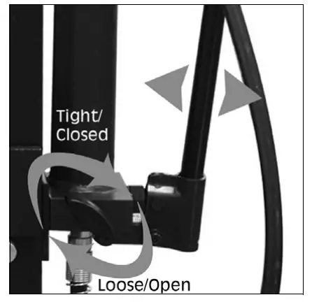
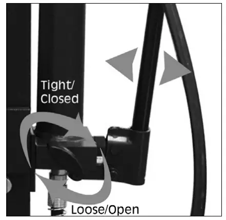
- Before using the press, purge any air from the system by opening the release valve by turning it anti-clockwise and pumping several full strokes to eliminate any air bubbles. Tight the release valve before continuing.
- Check all parts are secure and correctly aligned before using the press. The press is now ready for use.
POSITIONING THE BED
- Position the bed at the desired height, so it will be as close as possible to the ram when the workpiece is mounted on it.
FITTING THE MANDRELS OR PRESSURE CAP
Mandrels are available as an adaptor kit, any of which may be connected to the end of the ram using the adaptor.
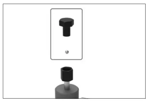
Alternatively, the basic ram pressure cap can be fitted as shown. Secure the pressure cap by tightening the grub screw with a suitable hex key.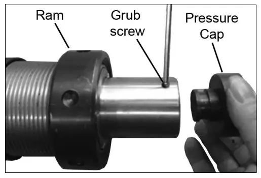
If one of the mandrels is required, the adaptor must be fitted instead of the pressure cap. Secure the adaptor by tightening the grub screw with a suitable hex key.
Select your mandrel depending upon the size of the workpiece bearing surface.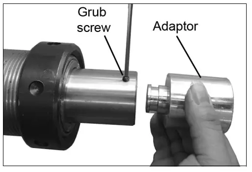 The mandrel can then be pushed into the adaptor where the built-in spring clip will hold it in place.
Store the mandrels in their positions on the mounting bracket when not in use.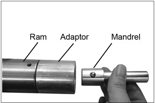
OPERATION
 WARNING: FAILURE TO HEED THE WARNINGS ON PAGE 3 MAY RESULT IN DAMAGE TO THE EQUIPMENT, OR FAILURE RESULTING IN PROPERTY DAMAGE OR PERSONAL INJURY.
- Place the workpiece on the bed. It must be completely stable and supported by packing or shims where required. ‘Heel’ blocks (arbor plates) are supplied, which are located on the bed. Place the workpiece on a combination of these to give it stability.
 CAUTION: DO NOT POINT LOAD THESE ACCESSORIES AS THEY ARE NOT DESIGNED TO TAKE THE FULL FORCE OF THE RAM IN ONE SPOT. SURE THEY ARE ADEQUATELY SUPPORTED
NOTE: Any packing pieces or shims used MUST be capable of withstanding the pressure that will be brought to bear, and MUST be of sufficient size with sufficient surface area, so as to avoid the possibility of slipping or springing out. Mating surfaces MUST be horizontal so that the force being exerted will NOT be at an angle. - Close the release valve by turning it clockwise until tightly closed.
- Pump the handle to bring the ram very lightly into contact with the workpiece.
- Maneuver the workpiece so that the desired point of contact is directly beneath the center of the ram.

- When satisfied that the workpiece is correctly aligned and is completely stable in that position, slowly pump the handle so that the ram begins to exert pressure on the workpiece. Continue to pump the handle whilst standing to the side. DO NOT stand directly in front of the work and constantly monitor the process and pressure gauge, ensuring the ram and work remain completely in line and there is no risk of slipping.
- When the process is complete, turn the release valve anticlockwise in small increments to release ram pressure and allow the removal of the workpiece.
![]() WARNING: NEVER USE EXTENSIONS TO THE RAM PUMPING HANDLE.
WARNING: NEVER USE EXTENSIONS TO THE RAM PUMPING HANDLE.
MAINTENANCE
- A visual inspection must be made before each use of the press, checking for leaking hydraulic fluid and damaged, loose, or missing parts.
- Owners and/or users should be aware that the repair of this equipment requires specialized knowledge and facilities. It is recommended that a thorough annual inspection of the press be made and that any defective parts be replaced with genuine Clarke parts
- Any press which appears to be damaged in any way is found to be badly worn, or operates abnormally SHOULD BE REMOVED FROM SERVICE until the necessary repairs are made.
- If the press is not to be used for any length of time, store it with the ram piston withdrawn and the operating handle in the lowered position to protect the moving parts.
PERIODICALLY
- Check the press frame to make sure all bolts are tight and inspect for cracked welds, bent, loose or missing parts.
- Check the hydraulic connections for leaks. Replace or properly repair any damaged or leaking hydraulic components before using. In the event of leaking seals, oil can be topped up via the filler plug at the end of the unit. Oil should be level with the mark on the dipstick. If necessary top up with CLARKE hydraulic oil, Part No 3050830. This task is carried out with the ram fully retracted.
- If any rust is apparent it must be removed completely and the paint restored.
DE-COMMISSIONING THE PRODUCT
Should the product become completely unserviceable and require disposal, draw off the oil into an approved container and dispose of the product and the oil according to local regulations.
TROUBLESHOOTING
| Problem | Probable Cause | Remedy |
| Pump will not work. | Dirt on valve seat/warns seals. | Bleed pump unit or have unit overhauled with new seals. |
| Pump will not produce pressure. Pump feels hesitant under load. Pump will not lower completely. | Air-lock-in system. | Open the release valve and remove the oil filler plug. Pump the handle a couple of full strokes and close the release valve. Replace the filler plug. |
| Pump will not deliver pressure. | The reservoir could be over-filled or have a low oil level. | Check the oil level by removing the filler plug and topping up to the correct level. |
| Pump feels hesitant under load. | The pump cup seal could be worn out. | Has the cup seal been replaced? |
| Pump will not lower completely. | Air-lock-in system. | Release air by removing the filler plug. |
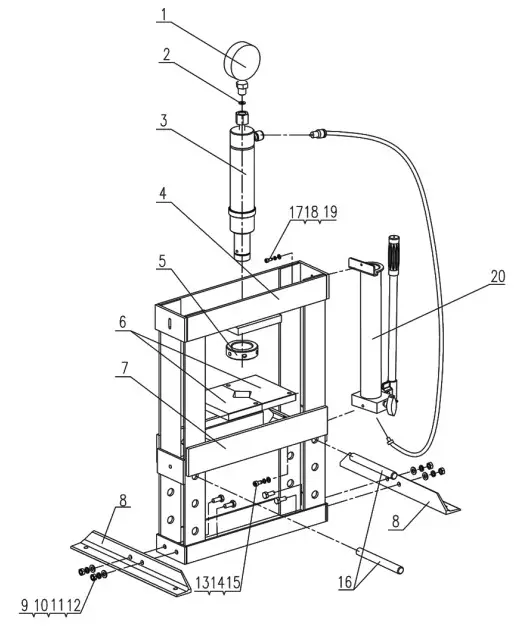
FRAME PARTS DIAGRAM
| FRAME PARTS | |||
| NO | DESCRIPTION | NO | DESCRIPTION |
| 1 | Pressure Gauge | 11 | Spring Washer 10 |
| 2 | Nylon Ring | 12 | Nuts, M10 |
| 3 | Press Cylinder | 13 | Bolt M8 x 16 |
| 4 | Frame | 14 | Spring Washer 8 |
| 5 | Locking Collar | 15 | Washer 8 |
| 6 | Heel Block | 16 | Rod |
| 7 | Bed Flat | 17 | Bolt M6 x 16 |
| 8 | Base Section | 18 | Spring Washer 6 |
| 9 | Bolt M10 x 25 | 19 | Hose Fitting |
| 10 | Washer 10 | 20 | Press Pump |
PUMP PARTS DIAGRAM
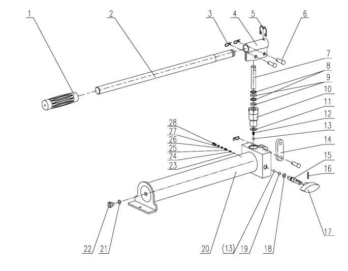
| PUMP PARTS | |||
| NO | DESCRIPTION | NO | DESCRIPTION |
| 1 | Handle Grip | 15 | Release Valve Stem |
| 2 | Handle | 16 | Pin, 3 x 20 |
| 3 | Torsional Spring Latch | 17 | Release Valve Stem Handle |
| 4 | Socket | 18 | 0-Ring |
| 5 | Socket Spring | 19 | 8mm Steel Ball |
| 6 | Pin | 20 | Base |
| 7 | Piston | 21 | 0-Ring, 8.5 x 2.65G |
| 8 | Seal | 22 | Seal Screw |
| 9 | 0-Ring | 23 | 2mm Steel Ball |
| 10 | Clamping Nut | 24 | Spring Plate |
| 11 | Copper Pad | 25 | Spring |
| 12 | Spring | 26 | 0-Ring |
| 13 | 6mm Steel Ball | 27 | Seal |
| 14 | Connecting Rod | 28 | Pressure Adjusting Screw |
RAM PARTS DIAGRAM
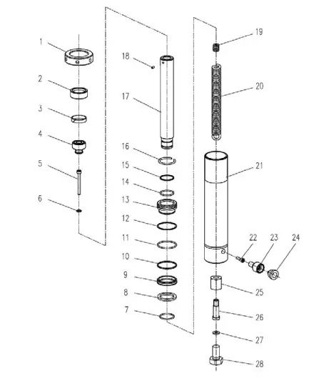
| RAM PARTS | |||
| NO | DESCRIPTION | NO | DESCRIPTION |
| 1 | End Cap | 15 | Ring |
| 2 | Upper Collar | 16 | Retaining Ring |
| 3 | Threaded Ring | 17 | Circlip |
| 4 | Guide Ring | 18 | Ram Piston |
| 5 | Bolt M8 x 70 | 19 | Spring Nut |
| 6 | Washer | 20 | Spring |
| 7 | Circlip | 21 | Cylinder Body |
| 8 | Circlip | 22 | Hex Socket Bolt M8 x 30 |
| 9 | Ring | 23 | Connector |
| 10 | Y-Ring | 24 | Dust Cap |
| 11 | Sealing Ring | 25 | Gauge Coupling |
| 12 | Ring | 26 | Connecting Insert |
| 13 | Retaining Ring | 27 | Sealing Washer |
| 14 | Threaded End | 28 | Bolt M20 x 25 |
DECLARATION OF CONFORMITY

PARTS & SERVICE:
0208 988 7400
Parts Enquiries
[email protected]
Servicing & Technical Enquiries
[email protected]
SALES: UK 01992 565333 or Export 00 44 (0)1992 565335![]() INTERNATIONAL Hemnall Street, Epping, Essex CM16 4LG
INTERNATIONAL Hemnall Street, Epping, Essex CM16 4LG
www.clarkeinternational.com


