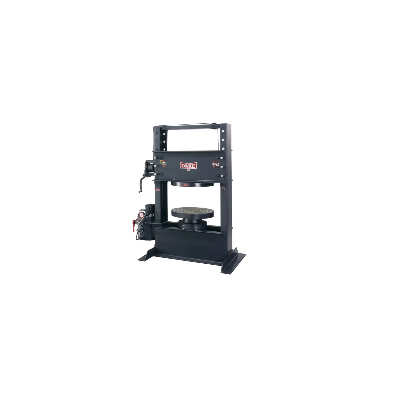
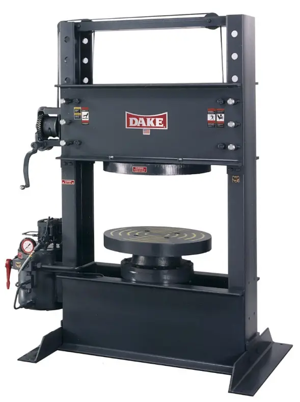
DAKE 33-578 Air Powered Tire Press
WARNING!
Read and understand all instructions and responsibilities before operating. Failure to follow safety instructions and labels could result in serious injury.
SAFEGUARDING THE POINT OF OPERATION
ANSI B11.2 – Hydraulic Power Presses – Safety Requirements for Construction, Care, and Use
It is important that Dake press users have a clear understanding of their responsibility involving the care and use of their Dake hydraulic press, including point-of-operation safe guards. Dake strongly recommends that Dake press users obtain a copy of the current American National Standard Institute (ANSI) B11.2 standard, for a more complete understanding of their responsibilities.
ANSI B11.2 states the following, relative to point of operation safeguarding:
“Normally, only the employer (press user) can determine the requirements of the press productions system components, including the dies and methods for feeding. Therefore, the employer is ultimately responsible to designate and provide the point-of-operation safeguarding system.”
The standard also discusses additional responsibilities of the employer. Some of the key responsibilities are:
- The employer is responsible for the safety, use, and care of the hydraulic power press production system.
- The employer is responsible to consider the sources of hazards for all tasks to be implemented on the hydraulic power press production system.
- The employer is required to eliminate or control identified hazards in the scope of their work activity.
- The employer is responsible for the training of personnel, caring for, inspecting, maintaining, and operating hydraulic press production systems to ensure their competence.
- The employer is responsible to provide and ensure that point-of-operation safeguarding is used, checked, maintained, and where applicable, adjusted on very production operation performed on a press production system.
A complete and current copy of the ANSI B.11.2 standard can be obtained by contacting the following:
American National Standards Institute
1430 Broadway
New York, NY 10018
AMT – The Association For Manufacturing Technology
7901 Westpark Drive
McLean, VA 22102
SPECIFICATIONS
| Model Number | 33-587 |
| Capacity | 150 Ton |
| Ram Travel | 12” |
| Width between Uprights | 36” |
| Max Daylight | 30” |
| Platen Diameter | 25” |
| Ram Advance Speed | 1-1/2 IPM |
| Return Speed | Gravity |
| Base | 66” x 42” |
| Height | 80” |
| Weight | 3,350 lbs. |
In the space provided record the serial number and model number of the machine. This information is only found on the black and gold Dake tag shown below. If contacting Dake this information must be provided to assist in identifying the specific machine.
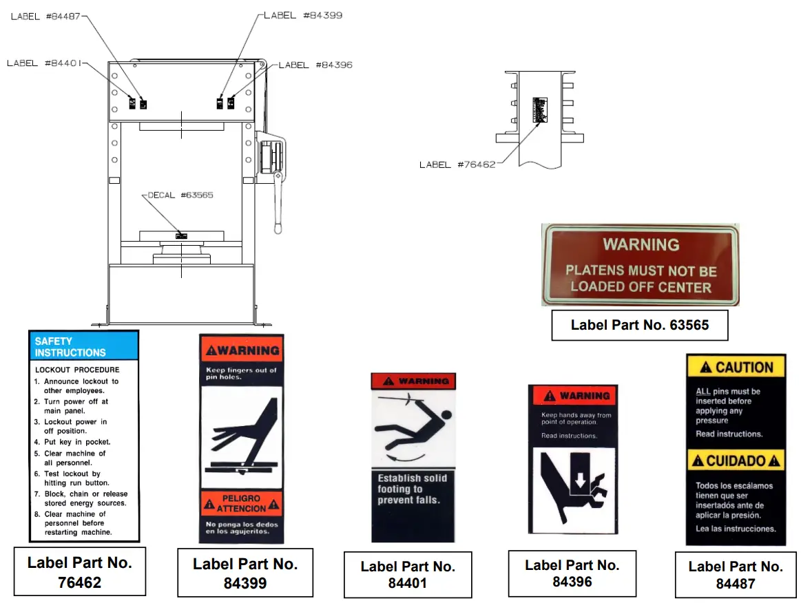
SAFETY
 This is the safety alert symbol. When you see this symbol on your press be alert to the potential for personal injury.
Employer is responsible to perform a hazard/PPE assessment before work activity.
Follow recommended precautions and safe operating practices.
- Carefully read all safety messages in these instructions and on your press safety signs. Keep safety labels in good condition. Replace missing or damaged safety labels.
- Do not alter this press from its original design.
- Do not make repairs or adjustments to any hydraulic system unless you are competent or working under competent supervision.
- Only use Dake original parts.
- This machine is intended to be operated by one person. This person should be conscious of the press ram movement not only for themselves but also for persons in the immediate area of the machine.
SET UP
- Anchor press to floor using 11/16” holes on the base angles of the press.
- Connect airline from source of supply to Pipe Tee located above operative valve.
- Fill press with oil. We recommend DTE Mobil 24 or equivalent hydraulic oil.
a. Remove 3/4” pipe plug from reservoir cover and 1/8” pipe plug located on the side of the reservoir.
b. Fill press with filtered oil through the reservoir cover until it starts weeping from the 1/8” pipe tapped hole on the side of the reservoir. Approximately 5 gallons.
c. Replace both pipe plugs.
OPERATION
HOIST
Press is equipped with hoist and hoist handle to raise and lower the upper platen to desired working height.
To change the vertical position of the upper platen sufficient tension must be applied to the hoist cable to permit removal of the table pins, then the upper platen may be moved to desired working position and all the table pins must be reinserted.
Be sure all table pins are on place before applying any pressure. Also make sure there is slack in the hoist cable before pressing. It is advisable to lower the upper platen opposed to running the ram and lower platen to the limit of its stroke.
PRESSING
- Make sure all the pins (6) are being used and that they are fully inserted in the upper head channel.
- Close the pressure release valve handle located on the left-hand side of the press. To do this pull forward and down on the red handle.
• Make sure that tires being pressed are centered on the lower platen. Failure to do this will cause the ram to work at an angle and damage the interior cylinder wall. - Once everything is in place and all safety precautions have been made, activate the press by pushing down on the air valve handle on the left-hand side of the press.
- The ram will raise the platen at the advance speed until contact is made and pressure is created then the press will work at the pressing speed until the work is done.
- Once the cycle is complete and the work has been done, pull out and up on the red pressure release handle. Once the pressure is removed using the valve handle gravity will return the lower platen down to its starting position.
MAINTENANCE
LUBRICATION
- Keep all working parts of the press well-oiled for easier operation.
- Keep a light film of oil over the entire surface of the ram to prevent rust.
REPLACING HYDRAULIC OIL
Recommended to replace hydraulic oil every 6 months of machine use.
*Amount needed may vary dependent on machine use*
TROUBLESHOOTING
When performing any maintenance make sure proper lockout procedure is followed. When disconnecting any parts of this machine be extremely careful that all parts are clean to prevent entrance of dirt in the hydraulic system.
A. Oil leaks around the piston.
- Oil above the Piston Seal or Leather: If rated stroke of the press is exceeded repeatedly by running the piston past rated stroke, bypass hole in the side of the cylinder run bypass line that connects above the piston leather. Eventually enough oil may accumulate so that when the piston is raised to the top of its stroke, oil is forced out between the piston and piston guide. This can be remedied by disconnecting the bypass tube line from the cylinder, then raising the piston slowly, about 2-1/2” less than it’s rated stroke (rated stroke: 18”) allowing the oil above the piston cap to overflow out the bypass hole into a clean bucket. Replace tube line. Oil may be put back into reservoir by removing the fill plug on the top of the reservoir.
- Check Valve not Seated: On the first presses made with rapid advance the bypass oil was returned through a check valve at the bottom of the reservoir. This has been changed since so that the oil is returned to the top of the reservoir, above the oil level. Previously, if the check valve failed to seat properly when the press was operated at rapid advance speed oil was forced back through the bypass line causing leakage around the piston. These old-style rapid advance presses can be improved by relocating the check valve in the inspection cover so that the oil from the bypass line discharges above oil level.
B. Press does not hold pressure.
- Loose tube Connection: Check all connections and tighten any loose tube nuts.
- Dirt under Release Valve Ball: Remove release valve stem, packing nut, packing, and ball. Clean out valve seat. Reseat valve ball using a brass rod as a drift and hit with significant force 2-3 times to reset ball. Reassemble valve. If this occurs frequently the oil should be drained from the reservoir and the reservoir should be flushed out. Fill reservoir with clean oil.
- Worn Leather Cup or Piston Seal: If neither of the previous conditions seem to be the cause of the press not holding pressure the trouble may be that the piston leather or T-ring & backers are worn out or damaged. To inspect remove lower platen and remove cap screws which bolt piston guide to the cylinder flange. Piston and guide may now be lifted out of the cylinder and inspected or replaced if necessary. Be careful not to damage the lip of the leather cup or T-ring as it enters the cylinder.
C. Press does not develop rated tonnage.
- Dirt under Release Valve Ball: See section above.
- Worn Leather Cup or Piston Seal: See section above.
- Air pressure too low: If the air supply is less that 90PSI the pump may develop less than the rated tonnage.
- Relief Valve set incorrect: When the press will not develop rated tonnage even though the air motor continues to pump. It may indicate that the oil is bypassing though the relief valve. The relief valve has been set at the factory to bypass oil back to the reservoir when press reaches rated tonnage. The load on the spring which governs the pressure at which the valve will bypass oil is adjusted by turning the threaded cap, Turning clockwise to increase the load on the spring or counterclockwise to decrease the load on the spring. After the valve is adjusted the cap is locked in place with a set screw, the relief valve not be tampered with after it is set to the capacity for the press.
D. Nothing happens when pumps are operated.
- Release Valve is open: Be sure release valve is firmly closed.
- Airline connected improperly: If air motors do not run when first time running the press check air line connections.
- Insufficient oil: This is not a likely to be the issue on a tire press but if the press will only make a fraction of its rated stroke and no more, check the oil level in the reservoir. With the ram down the oil should be about 4” from the top of the reservoir.
- Repaired Improperly: If press has had any maintenance in the past it is possible that a check valve spring or check ball got missed in the repairs.
E. Press is too slow.
- Air pressure too low: If the airline is not large enough to travel a distance from the compressor it may result in a large pressure drop in the line while air is being used. Check for pressure drop by installing an air gauge near the inlet of the press.
- Wrong oil: Oil that is too heavy will slow the pressing speed. DTE Mobil 24 or equivalent hydraulic oil.
HYDRAULIC DIAGRAM
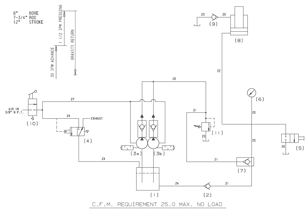
| Item | Part No. | Description | Qty |
| 1 | 1904P | Reservoir | 1 |
| 2 | 700232 | Check Valve | 1 |
| 3 | 63453 | Air Pumps | 2 |
| 4 | 1911 | Quick Exhaust Valve | 1 |
| 5 | 710557 | Release Valve | 1 |
| 6 | 71268 | Gauge | 1 |
| 7 | 700147 | Check Valve | 1 |
| 8 | 707070A | Workhead | 1 |
| 9 | 1841 | Check Valve | 1 |
| 10 | 1912 | 3-Way Valve | 1 |
| 11 | 701350 | Relief Valve | 1 |
EXPLODED VIEWS & PARTS LISTS
| Item | Part No. | Description | Qty |
| 1551P | Base Angle | 2 | |
| 700147 | Check Valve Assembly | 1 | |
| 700232 | Check Valve Assembly | 1 | |
| 583 | Clamp, Cable (1/4″ Cable) | 4 | |
| 63565 | Decal, Tire Press – Platens Must Not Be Loaded Off-Center | 1 | |
| 58227 | Fitting, Pipe, Straight (3/4″ Male Pipe Nipple with Hex) | 1 | |
| 58226 | Fitting, Pipe, Straight (Nipple, 3/8 x 3/8 Male NPTF) | 6 | |
| 58225 | Fitting, Pipe, Straight 1/4 X 1/4 Male NPTF | 1 | |
| 1252 | Fitting, Tube, 37 Deg. (90 Deg. Elbow, 1/2 x 3/8 NPTF) | 2 | |
| 1511 | Fitting, Tube, 37 Deg. (Male Branch Tee, 3/8 x 1/4 NPTF) | 1 | |
| 73425 | Fitting, Tube, 37 Deg. (Straight, 3/8 x 3/8 NPTF) | 1 | |
| 72047 | Fitting, Tube, 37 Deg. (Swivel Nut Elbow, 3/8) | 1 | |
| 1909P | Frame | 1 | |
| 300168 | Ganged Warning Label. Combined. | 1 | |
| 71268 | Gauge, 150 Ton Hand – 1/4″ NPT Male Bottom | 1 | |
| 701653 | Hoist Crank Assembly, W/Bearing, 150 Ton, (Consists of Items: 387 Crank & 606 Handle) | 1 | |
| 84487 | Label, Caution. Table Pins Inserted before Pressing | 1 | |
| 76462 | Label, Lockout Procedure | 1 | |
| 607 | Label, Model Number | 1 | |
| 24798 | Label, Warning – Air Must be Moisture Free | 1 | |
| 84399 | Label, Warning – Keep Fingers Out of Pin Holes | 1 | |
| 36863 | Label, Warning , End of Stroke | 1 | |
| 43647 | Lock Washer (1/2) | 2 | |
| 43648 | Lock Washer (5/8) | 4 | |
| 81003 | Name Plate, Dake | 1 | |
| 44194 | Nipple, Pipe XS, (3/4 x 2-1/2) | 1 | |
| 43919 | Nut, Hex (3/4-10) | 8 | |
| 43917 | Nut, Hex (5/8-11) | 4 | |
| 77271 | Pin, Spring (3/8″ x 2-1/2″) | 6 | |
| 7205P | Pin, Table | 6 | |
| 596 | Pipe Plug (1/2 NPTF) | 1 | |
| 589 | Pipe Plug (1/8 NPTF) | 1 | |
| 1745 | Pipe Plug (3/4) | 1 | |
| 588 | Pipe Plug (3/8 NPTF) | 1 | |
| 1127 | Pipe, Reducer Bushing (1/2 x 3/8 Hex) | 1 | |
| 1798P | Platen, Lower | 1 | |
| 1813P | Platen, Upper | 1 | |
| 701825T01 | Pressure Tube Assembly | 1 | |
| 703770 | Pressure Tube Assembly, Release Valve to Cylinder | 1 | |
| 1563P | Pulley, 125 & 150 Ton | 2 | |
| 1809P | Pulley, Cable | 2 | |
| 63453 | Pump, Air Driven | 2 | |
| 710557 | Release Valve Assembly, | 1 | |
| 701350 | Relief Valve Assembly, | 1 | |
| 1904P | Reservoir | 1 |
| 1822P | Reservoir Cover | 1 | |
| 43978 | Ring, Retaining (3/4″ Shaft Size) | 6 | |
| 302816 | Safety Pin for Table Pins | 6 | |
| 43347 | Screw (1/2-13 x 1) | 6 | |
| 43365 | Screw (5/8-11 x 1-3/4) | 4 | |
| 43348 | Screw , Hex Cap (1/2-13 x 1-1/4) | 8 | |
| 70277 | Screw, Drive (#4 x 5/16″ Round Hd. Type U) | 6 | |
| 43349 | Screw, Hex Cap (1/2-13 x 1-1/2) | 2 | |
| 43373 | Screw, Hex Cap (3/4-10 x 2) | 4 | |
| 24569 | Screw, Soc Cap (3/4-10 x 3-1/4) | 4 | |
| 1810P | Shaft, Cable Pulley | 1 | |
| 1811P | Shaft, Cable Pulley | 2 | |
| 1819P | Stop Block | 4 | |
| 700111-S | Table Hoist Sub Assembly, Also need Hoist Crank Assembly 701653 | 1 | |
| 1553P | Table Spacer | 4 | |
| 79957 | Tag, Hook Air Line Here | 1 | |
| 79956 | Tag, No Oil in Reservoir | 1 | |
| 713339T02 | Tube Assembly | 1 | |
| 713339T03 | Tube Assembly | 1 | |
| 713339T04 | Tube Assembly | 1 | |
| 713339T06 | Tube Assembly | 1 | |
| 701825T02 | Tube Assembly, By-Pass | 1 | |
| 1912 | Valve, 3-Way Air | 1 | |
| 1911 | Valve, Quick Exhaust | 1 | |
| 43649 | Washer, Lock (3/4) | 4 | |
| 707070A | Workhead Assembly | 1 |
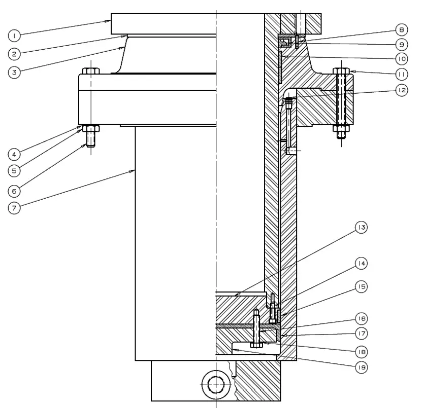
707070A Workhead Assembly – New Style | |||
| Item | Part No. | Description | Qty |
| 1 | 1796P | Piston | 1 |
| 2 | 52478P | Retainer | 3 |
| 3 | 31871 | Guide, Piston | 1 |
| 4 | 43647 | Washer, Lock (1/2”) | 10 |
| 5 | 43419 | Screw, Soc Cap (1/4-20 x 2) | 4 |
| 6 | 43359 | Screw, Hex Cap (1/2-13 x 4-1/2) | 4 |
| 7 | 1793P | Cylinder | 1 |
| 8 | 43817 | Screw, Fl. Hd. Slot Mach. (#10-24 x 1/2) | 3 |
| 9 | 1871 | Oil Seal, | 1 |
| 10 | 31400 | Wear Ring | 2 |
| 11 | 43358 | Screw, Hex Cap (1/2-13 x 4) | 6 |
| 12 | 589 | Pipe Plug (1/8 NPTF) | 2 |
| 13 | 87611P | Piston Cap | 1 |
| 14 | 43916 | Hex Nut, (1/2-13) | 10 |
| 15 | 31399 | Wear Ring | 1 |
| 16 | 37052 | 1-T-ring, 2-backers | 1 |
| – | 707070A | Workhead Assembly (Includes Items: 1-3, 5-16) | – |
| – | 703922 | Workhead Repair Kit (For 707070 & 707070A) Includes Items : 9, 10, 15 & 16. | – |
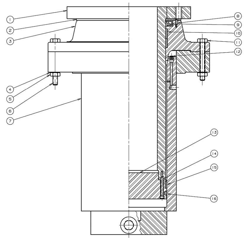
707070 Workhead Assembly – Old Style | |||
| Item | Part No. | Description | Qty |
| 1 | 1796P | Piston | 1 |
| 2 | 52478P | Retainer | 3 |
| 3 | 31871 | Guide, Piston | 1 |
| 4 | 43647 | Washer, Lock (1/2”) | 10 |
| 5 | 43916 | Screw, Soc Cap (1/4-20 x 2) | 10 |
| 6 | 43359 | Screw, Hex Cap (1/2-13 x 4-1/2) | 4 |
| 7 | 1793P | Cylinder | 1 |
| 8 | 43817 | Screw, Fl. Hd. Slot Mach. (#10-24 x 1/2) | 3 |
| 9 | 1871 | Oil Seal, | 1 |
| 10 | 31400 | Wear Ring | 2 |
| 11 | 43358 | Screw, Hex Cap (1/2-13 x 4) | 6 |
| 12 | 589 | Pipe Plug (1/8 NPTF) | 2 |
| 13 | 30425P | Piston Cap | 1 |
| 14 | 43417 | Screw, Soc Cap (1/4-20 x 1-1/2) | 4 |
| 15 | 31399 | Wear Ring | 1 |
| 16 | 43332 | Screw (3/8-16 x 1-3/4) | 8 |
| 17 | 1538 | Piston Leather | 1 |
| 18 | 43645 | Washer, Lock (3/8”) | 8 |
| 19 | 1536 | Ring, Supporting | 1 |
| N/A | 1567 | Pipe Plug (1/4 NPTF) | 2 |
| – | 707070 | Workhead Assembly (Includes all items above) | – |
| – | 703922 | Workhead Repair Kit (For 707070 & 707070A) Includes Items : 9, 10, 15 & 17. | – |
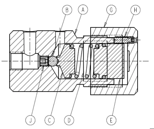
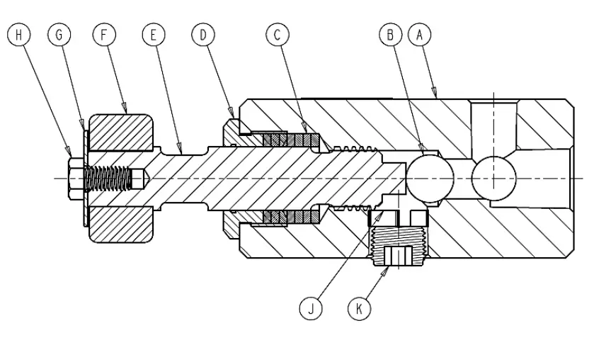
701350 Relief Valve Assembly | |||
| Item | Part No. | Description | Qty |
| A | 1093P | Relief Valve Body | 1 |
| B | 1222 | Valve, Ball (5/16″) | 1 |
| C | 1094P | Retainer, Ball | 1 |
| D | 1221 | Spring, Valve Compressor | 1 |
| E | 1095P | Retainer, Spring | 1 |
| F | 1111 | O-Ring, Unif 215 Buna | 1 |
| G | 1096P | Relief Valve Cap | 1 |
| H | 43548 | Screw, Soc Set (#10-24 x 3/4, Cup Point) | 1 |
| J | 1780P | Valve Seat | 1 |
| – | 701350 | Relief Valve Assembly – Includes all item above | – |
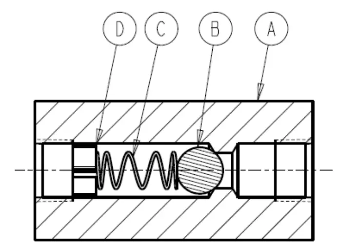
700232 Check Valve Assembly | |||
| Item | Part No. | Description | Qty |
| A | 1825 | Body, Check Valve | 1 |
| B | 586 | Valve, Ball (1/2″) | 1 |
| C | 890 | Spring, Check Valve | 1 |
| D | 1109 | Retainer, Ball | 1 |
| – | 700232 | Check Valve Assembly – Includes all item above | – |
710557 Release Valve Assembly | |||
| Item | Part No. | Description | Qty |
| A | 1752P | Release Valve Block | 1 |
| B | 1936 | Valve, Ball | 1 |
| C | 1937 | Washer, Valve Rod Packing | 8 |
| D | 1931P | Packing Nut | 1 |
| E | 47946P | Release Valve Rod | 1 |
| F | 2230A | Handle, Release Valve | 1 |
| G | 348 | Spindle Washer (1-1/2″ OD x .40″ ID x 1/16 Thick) | 1 |
| H | 43326 | Hex Cap Screw (3/8-16 x 3/4) | 1 |
| J | 1935 | Ball, Retainer | 1 |
| K | 596 | Pipe Plug (1/2 NPTF) | 1 |
| – | 710557 | Release Valve Assembly – Includes all items above | – |
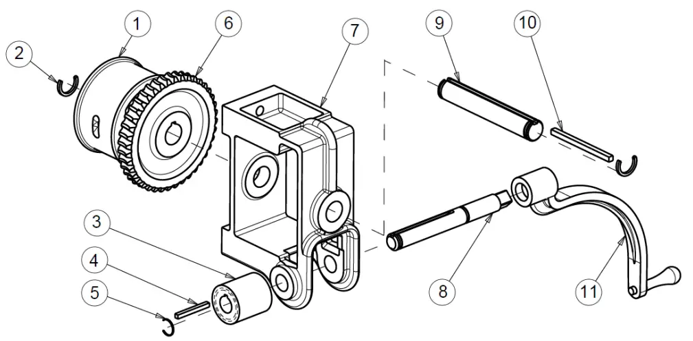
TABLE HOIST ASSEMBLY
| Item | Part No. | Description | Qty |
| 1 | 740 | Cable Drum | 1 |
| 2 | 43983 | Ring, Retaining (1-1/4” Shaft Size) | 2 |
| 3 | 744 | Worm, | 1 |
| 4 | 746 | Worm Shaft Key (1/4 x 1/4 x 3-7/16) | 1 |
| 5 | 43982 | Ring, Retaining (1” Shaft Size) | 2 |
| 6 | 743 | Gear, Worm | 1 |
| 7 | 739 | Hoist Frame | 1 |
| 8 | 742 | Worm Shaft | 1 |
| 9 | 741 | Drum Shaft | 1 |
| 10 | 745 | Drum Shaft Key (5/16 x 5/16 x 4) | 1 |
| 11 | 701653 | Rachet Handle Assembly | 1 |
| N/A | 45954 | Cable, 1/4 Dia. | 19ft |
| – | 700111-S | Hoist Assembly (Parts 1-10) | – |
701825T01 Pressure Tube Assembly | ||
| Part No. | Description | Qty |
| Part | Part Description | QTY |
| 51456 | Fitting, Tube, 37 Deg. (Inch Sleeve- SAE 14) | 2 |
| 51455 | Fitting, Tube, 37 Deg. (Nut, 7/8-37 Deg. Flare Style “B”) | 2 |
| 1943 | Fitting, Tube, 37 Deg. (Straight, 7/8 x 3/4 NPTF) | 2 |
| 45925 | Tubing 7/8″x.120 | 12″ |
701825T02 By-Pass Tube Assembly | ||
| Part No. | Description | Qty |
| Part | Part Description | QTY |
| 1248 | Fitting, Tube, 37 Deg. (90 Deg. Elbow, 3/8 x 1/4 NPTF) | 1 |
| 1249 | Fitting, Tube, 37 Deg. (Run Tee, 3/8 x 1/4 NPTF) | 1 |
| 76221 | Fitting, Tube, Nut | 2 |
| 1102 | Pipe, Reducer Bushing (3/8 x 1/4 Hex Steel) | 1 |
| 45923 | Tubing, 3/8″x.065 | 12″ |
713339T03 Tube Assembly | ||
| Part No. | Description | Qty |
| Part | Part Description | QTY |
| 1248 | Fitting, Tube, 37 Deg. (90 Deg. Elbow, 3/8 x 1/4 NPTF) | 1 |
| 51456 | Fitting, Tube, 37 Deg. (Inch Sleeve- SAE 14) | 2 |
| 51455 | Fitting, Tube, 37 Deg. (Nut, 7/8-37 Deg. Flare Style “B”) | 2 |
| 45923 | Tubing, 3/8″x.065 | 12″ |
713339T04 Tube Assembly | ||
| Part No. | Description | Qty |
| 1248 | Fitting, Tube, 37 Deg. (90 Deg. Elbow, 3/8 x 1/4 NPTF) | 1 |
| 51456 | Fitting, Tube, 37 Deg. (Inch Sleeve- SAE 14) | 2 |
| 51455 | Fitting, Tube, 37 Deg. (Nut, 7/8-37 Deg. Flare Style “B”) | 2 |
| 1247 | Fitting, Tube, 37 Deg. (Straight, 3/8 x 1/4 NPTF) | 1 |
| 45923 | Tubing, 3/8″x.065 | 12″ |
713339T06 Tube Assembly | ||
| Part No. | Description | Qty |
| 1251 | Fitting, Tube, 37 Deg. (Straight, 1/2 x 3/8 NPTF) | 2 |
| 46614 | Nut, Flare (Nut, 1/2-37 Deg. Flare Style “B”) | 2 |
| 45924 | Tubing 1/2″x.083 | 30″ |
701825T02 By-Pass Tube Assembly | ||
| Part No. | Description | Qty |
| Part | Part Description | QTY |
| 1330 | Coupling, Pipe (1/4″) | 1 |
| 51456 | Fitting, Tube, 37 Deg. (Inch Sleeve- SAE 14) | 2 |
| 51455 | Fitting, Tube, 37 Deg. (Nut, 7/8-37 Deg. Flare Style “B”) | 2 |
| 1247 | Fitting, Tube, 37 Deg. (Straight, 3/8 x 1/4 NPTF) | 2 |
| 45923 | Tubing, 3/8″x.065 | 12″ |
| 1841 | Valve, Check | 1 |
ORDERING INFORMATION
Please contact factory for current prices.
Parts are available for direct purchase from Dake or through a distributor. When placing a parts order, you will need to provide the part number, name of part, and model number. All parts shipped F.O.B. Factory in Grand Haven, MI.