SmartGen HMP300 Power Integrated Protection Module User Manual

SmartGen
All rights reserved. No part of this publication may be reproduced in any material form (including photocopying or storing in any medium by electronic means or other) without the written permission of the copyright holder.
Applications for the copyright holder’s written permission to reproduce any part of this publication should be addressed to Smartgen Technology at the address above. Any reference to trademarked product names used within this publication is owned by their respective companies.
SmartGen Technology reserves the right to change the contents of this document without prior notice.
Table 1 Software Version
| Date | Version | Note |
| 2017-09-22 | 1.0 | Original release. |
| 2019-11-05 | 1.1 | Added differential protection contents. |
| 2021-03-05 | 1.2 | Modify the figure 1 error and update the format. |
| 2022-10-11 | 1.3 | Update company logo and manual format. |
OVERVIEW
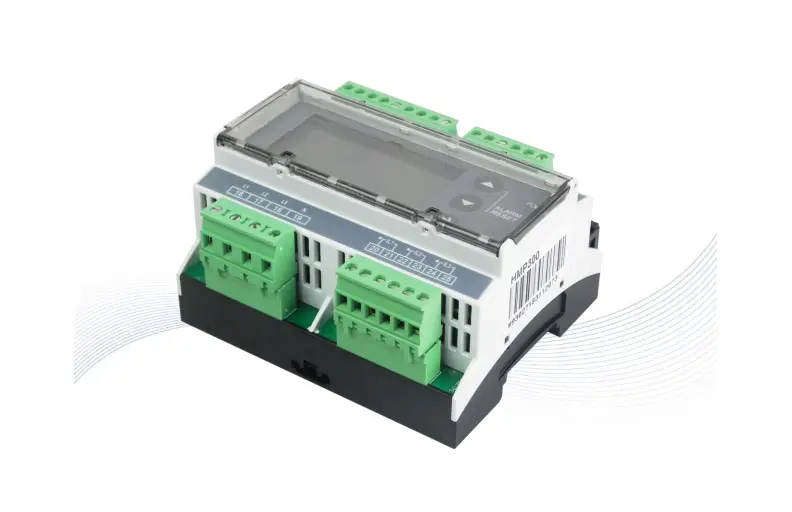
HMP300 power integrated protection module integrates digital, intelligent and network technology, and is used for collecting generator-set data (voltage, current, power and frequency) and related action output for data errors to protect the device. It fits with LCD display, optional Chinese and English bilingual interface, and it is reliable and easy to use.
HMP300 power integrated protection module adopts micro-processor technology with precise parameter measuring, fixed value adjustment, set value adjusting functions etc. All parameters can be configured from front panel or through LINK interface via PC. It can be widely used in all types of marine/land electrical device with compact structure, advanced circuits, simple connections and high reliability.
PERFORMANCE AND CHARACTERISTICS
Main features are as below:
- 132×64 LCD display with backlight, selectable language interface (Chinese and English), push-button operation.
- Equipped with LINK communication port; Through LINK interface on PC, data and parameters can be monitored and adjusted.
- Equipped with CANBUS port, which can connect with HMC9000/HMC6000 module to realize power and engine data collecting and display at the same time.
- Differential protection function, and controller will issue related alarm information after differential protection is active.
- Protections for over/under voltage, over/under frequency, reverse power, over power and over current.
➢ Harmonic test function, and each phase voltage/current harmonic distortion rate can be tested. - Suitable for 3-phase 4-wire, 3-phase 3-wire, single phase 2-wire, and 2-phase 3-wire systems with frequency 50/60Hz.
- Collects and shows 3-phase voltage, 3-phase current, frequency and power parameters.
Generator
Line voltage (Uab, Ubc, and Uca)
Phase voltage (Ua, Ub, and Uc)
Frequency Hz
Load
Current Ia, Ib, Ic A (unit)
Each phase and total active power P kW (unit)
Each phase and total reactive power Q kvar (unit)
Each phase and average power factor P - Parameter setting function: users are allowed to set and change parameters and parameters shall be stored in internal FLASH memory and cannot be lost even in case of power outage; most of them can be adjusted using front panel of the controller.
- Wide power supply range DC (8~35) V, suitable for different starting battery voltage environment.
- All parameters apply digital adjustment, instead of conventional analog modulation with normal potentiometer, improving whole reliability and stability.
- Module is mounted on the 35mm guide rail.
SPECIFICATION
Table 2 Technical Parameters
| Item | Content |
| Operating Voltage | DC8.0V to DC35.0V, Continuous Power Supply |
| Power Consumption | <3W (standby ≤2W) |
| Alternator Volt Input Range 3Phase 4Wire 3Phase 3Wire Single Phase 2Wire 2Phase 3Wire | 30V AC ~ 360 V AC (ph-N) 30V AC ~ 620 V AC (ph-ph) 30V AC ~ 360 V AC (ph-N) 30V AC ~ 360 V AC (ph-N) |
| Alternator Frequency | 50Hz/60Hz |
| Programmable Relay Output 1 | 5A AC250V volt free output |
| Programmable Relay Output 2 | 5A AC250V volt free output |
| Programmable Relay Output 3 | 10A AC250V volt free output |
| Programmable Relay Output 4 | 10A AC250V volt free output |
| Overall Dimension | 107.6mm x 89.7mm x 60.7mm |
| CT Secondary Current | 5A rated |
| Working Temperature | (-25~+70)°C |
| Working Humidity | (20~93)% |
| Storage Temperature | (-25~+70)°C |
| Insulating Intensity | Apply AC2.2kV voltage between high voltage terminal and low voltage terminal and the leakage current is not more than 3mA within 1min |
| Weight | 0.30kg |
OPERATION
Table 3 Key Description
| Icons | Function | Description |
 | Set/Confirm | Pressing this key will enter into password screen; In setting parameter status, pressing this key will shift cursor or confirm the set value. |
 | Up/Increase | Scrolls the screen up; Shift the cursor up or increase the set value in parameter setting menu. |
 | Down/Decrease | Scrolls the screen down; Shift the cursor down or decrease the set value in parameter setting menu. |
| Pressing both | ||
SCREENS DISPLAY
POWER DATA DISPLAY
Table 4 Power Data Display
| 1st Screen | Description |
| UL-L 380V 380V 380 V UL-N 220V 220V 220 V I: 500A 500A 500 A P: 276 kW Q : 200 kvar PF 0.80 50.0Hz | Line voltage Uab, Ubc, Uca |
| Phase voltage Ua, Ub, Uc | |
| Current Ia, Ib, Ic | |
| Active power, reactive power | |
| Average power factor, frequency | |
| 2nd Screen | Description |
| P(kW) Q(kvar) S(kVA) A: 89.0 65.0 110.0 B: 89.0 65.0 110.0 C: 89.0 65.0 110.0 PF 0.80 0.80 0.80 | Active power display, reactive power display, apparent power display |
| A phase: active power, reactive power, apparent power | |
| B Phase: active power, reactive power, apparent power | |
| C Phase: active power, reactive power, apparent power | |
| A phase, B phase and C phase power factors | |
| 3rd Screen | Description |
| THDu(%) THDi(%) A: 0.5 0.3 B: 0.5 0.3 C: 0.5 0.3 Phase Seq: 0° 120° 240° | Voltage harmonic distortion rate, current harmonic distortion rate |
| A phase: voltage/current harmonic distortion rate | |
| B phase: voltage/current harmonic distortion rate | |
| C phase: voltage/current harmonic distortion rate | |
| Phase sequence | |
| 4th Screen | Description |
| Total kWh 276.3 kWh Total kvarh 200.0 kvarh kWh % 32% kvarh % 32% | Total active energy Total reactive energy |
| Active power percentage Reactive power percentage |
ALARM DISPLAY
All alarm information (trip alarm and warning alarm) collected by the module is real time displayed on the alarm screen as bellow:
Table 5 Alarm Display
| Display Content | Description |
| Alarm Warning Alarm Under Volt Warning | Page title |
| Alarm type | |
| Alarm content | |
MODULE INFORMATION DISPLAY
Module information including output port status, software version, hardware version and release time can be displayed on this screen as bellow:
Table 6 Module Information Display
| Display Content | Description |
| OUT: 1 2 3 4
Software Version: V1.3 Hardware Version: V2.1 Issue Date: 2017-09-20 | Output port number |
| Outputs status | |
| Software version | |
| Hardware version | |
| Issue date |
PROTECTION
WARNING
When controller detects the warning signals, alarm indicator flashes and LCD displays the warning information.
Table 7 Module Warning Types
| No. | Type | Description |
| 1 | Over Voltage | When the module detects that the genset voltage has exceeded the pre-set value, it will initiate a warning alarm and the corresponding alarm information will be displayed on LCD. |
| 2 | Under Voltage | When the module detects that the genset voltage has fallen below the pre-set value, it will initiate a warning alarm and the corresponding alarm information will be displayed on LCD. |
| 3 | Over Frequency | When the module detects that the genset frequency has exceeded the pre-set value, it will initiate a warning alarm and the corresponding alarm information will be displayed on LCD. |
| 4 | Under Frequency | When the module detects that the genset frequency has fallen below the pre-set value, it will initiate a warning alarm and the corresponding alarm information will be displayed on LCD. |
| 5 | Over Power | When the module detects that the genset power (power is positive) has exceeded the pre-set value, it will initiate a warning alarm and the corresponding alarm information will be displayed on LCD. |
| 6 | Over Current | When the module detects that the genset current has exceeded the pre-set value, it will initiate a warning alarm and the corresponding alarm information will be displayed on LCD. |
| 7 | Current Pre-alarm | When module detects genset current is above the current pre-alarm limit, it will initiate a warning alarm and the corresponding alarm information will be displayed on LCD. |
| 8 | Reverse Power | When the module detects that the genset reverse power value (power is negative) has exceeded the pre-set value, it will initiate a warning alarm and the corresponding alarm information will be displayed on LCD. |
| 9 | Differential Protection | When module detects differential current is above the pre-set current pre-alarm limit, it will initiate a warning alarm and the corresponding alarm information will be displayed on LCD. |
TRIP ALARM
When controller detects trip alarm, it will send signals to trip the generator and the corresponding alarm information will be displayed on LCD.
Table 8 Trip Alarms
| No. | Type | Description |
| 1 | Over Voltage | When the module detects that the genset voltage has exceeded the pre-set value, it will initiate a trip alarm and the corresponding alarm information will be displayed on LCD. |
| 2 | Under Voltage | When the module detects that the genset voltage has fallen below the pre-set value, it will initiate a trip alarm and the corresponding alarm information will be displayed on LCD. |
| 3 | Over Frequency | When the module detects that the genset frequency has exceeded the pre-set value, it will initiate a trip alarm and the corresponding alarm information will be displayed on LCD. |
| 4 | Under Frequency | When the module detects that the genset frequency has fallen below the pre-set value, it will initiate a trip alarm and the corresponding alarm information will be displayed on LCD. |
| 5 | Over Power | When the module detects that the genset power (power is positive) has exceeded the pre-set value, it will initiate a trip alarm and the corresponding alarm information will be displayed on LCD. |
| 6 | Over Current | When the module detects that the genset current has exceeded the pre-set value, it will initiate a warning alarm and the corresponding alarm information will be displayed on LCD. |
| 7 | Differential Protection | When the module detects differential current is above the pre-set limit, it will initiate a warning alarm and the corresponding alarm information will be displayed on LCD. |
| 8 | Reverse Power | When the module detects that the genset reverse power value (power is negative) has exceeded the pre-set value, it will initiate a warning alarm and the corresponding alarm information will be displayed on LCD. |
| 9 | Loss of Phase | When the module detects that genset voltage phase loss, it will initiate trip alarm signals and the corresponding alarm information will be displayed on LCD. |
| 10 | Reverse Phase Sequence | When the module detects that genset voltage phase sequence wrong, it will initiate trip alarm signals and the corresponding alarm information will be displayed on LCD. |
WIRING CONNECTION
HMP300 controller panel is as below: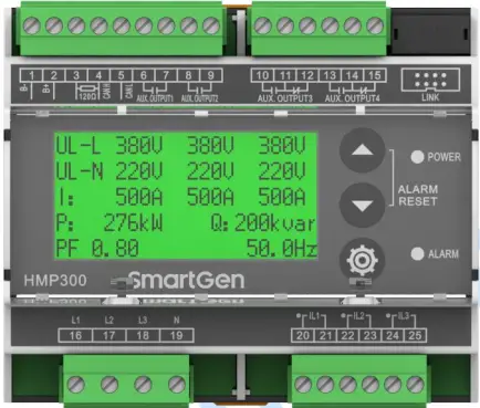
Fig. 1 HMP300 Panel Diagram
Table 9 Terminal Wiring Connection
| No. | Function | Cable Size | Remarks | |
| 1 | B- | 1.5mm2 | Connected with negative of starter battery, engine starter battery can be used directly. | |
| 2 | B+ | 1.5mm2 | Connected with positive of starter battery, engine starter battery can be used directly. | |
| 3 | 120Ω | 1.0mm2 | After short connecting with CANL, it doesn’t need to externally connect with 120Ω. | |
| 4 | CANH | 1.0mm2 | CANBUS Communication port, which supports J1939-81 power data communication protocol. | |
| 5 | CANL | 1.0mm2 | ||
| 6 | Aux. Output 1 | 1.0mm2 | Relay normally open volt free contact, rated 5A, and volt free contact output. |
Details see 8.2. |
| 7 | 1.0mm2 | |||
| 8 | Aux. Output 2 | 1.0mm2 | Relay normally open volt free contact, rated 5A, and volt free contact output. | |
| 9 | 1.0mm2 | |||
| 10 | Aux. Output 3 | 1.0mm2 | Relay normally open volt free contact, rated 10A, and volt free contact output. | |
| 11 | 1.0mm2 | |||
| 12 | 1.0mm2 | |||
| 13 | Aux. Output 4 | 1.0mm2 | Relay normally open volt free contact, rated 10A, and volt free contact output. | |
| 14 | 1.0mm2 | |||
| 15 | 1.0mm2 | |||
| 16 | Gen L1 Phase Volt Monitoring Input | 1.0mm2 | Connect with output U Phase of generator (2A fuse is recommended) | |
| 17 | Gen L2 Phase Volt Monitoring Input | 1.0mm2 | Connect with output V Phase of generator (2A fuse is recommended). | |
| 18 | Gen L3 Phase Volt Monitoring Input | 1.0mm2 | Connect with output W Phase of generator (2A fuse is recommended). | |
| 19 | Gen N Wire Input | 1.0mm2 | Connect with output N Wire of generator. | |
| 20 | CT A-Phase Monitoring Input | 2.5mm2 | External connected current transformer secondary coil (rated 5A). | |
| 21 | 2.5mm2 | |||
| 22 | CT B-Phase Monitoring Input | 2.5mm2 | External connected current transformer secondary coil (rated 5A). | |
| 23 | 2.5mm2 | |||
| 24 | CT C-Phase Monitoring Input | 2.5mm2 | External connected current transformer secondary coil (rated5A). | |
| 25 | 2.5mm2 | |||
| LINK | Test software interface. Connect with PC test software via SG72 module. | |||
SCOPES AND DEFINITIONS OF PROGRAMMABLE PARAMETERS
CONTENTS AND SCOPES OF PARAMETERS
Table 10 Parameter Setting Contents and Scopes
| No. | Items | Range | Default | Description |
| Voltage Settings | ||||
| 1 | AC System | (0-3) | 0 | 0: 3P4W 1: 3P3W 2: 2P3W 3: 1P2W |
|
2 |
Rated Voltage |
(30-30000)V |
230 | Provide standard for over/under voltage and voltage on load. If voltage transformer is used, this value is primary voltage of transformer. When AC system is 3P3W, this setting value is line voltage; for other supply AC systems, it is phase voltage. |
| 3 | Voltage Transformer Enabled | (0-1) 0: Disabled 1: Enabled | 0 | Disabled |
| 4 | Primary Voltage | (30-30000)V | 100 | Primary voltage of voltage transformer. |
| 5 | Secondary Voltage | (30-1000)V | 100 | Secondary voltage of voltage transformer. |
| 6 | Over Volt Warning Enabled | (0-1) 0: Disabled 1: Enabled | 1 | When it is enabled, module starts to detect over voltage warning. |
| 7 | Over Volt Warning Value | (0-200)% | 110% | When generator voltage has exceeded the set value and warning delay is expired, module will initiate over voltage warning alarm. |
| 8 | Over Volt Warning Delay | (0-3600)s | 3 | Time duration from alarm is detected to it initiates alarm. |
| 9 | Over Volt Trip Enabled | (0-1) 0: Disabled 1: Enabled | 1 | When it is enabled, module starts to detect over voltage trip. |
| 10 | Over Volt Trip Value | (0-200)% | 120 | When generator voltage has exceeded the set value and trip delay is expired, module will initiate over voltage trip alarm. |
| 11 | Over Volt Trip Delay | (0-3600)s | 2 | Time duration from alarm is detected to it initiates alarm. |
| 12 | Under Volt Warning Enabled | (0-1) 0: Disabled 1: Enabled | 1 | When it is enabled, module starts to detect under voltage warning. |
| 13 | Under Volt Warning Value | (0-200)% | 84 | When generator voltage has fallen below the set value and warning delay is expired, module will initiate under voltage warning |
2 DEFINED CONTENTS OF PROGRAMMABLE OUTPUT PORTS 1~4
Table 11 Defined Contents of Programmable Output Ports 1-4
| No. | Items | Description |
| 0 | Not Used | Output port is deactivated when “Not Used” is selected. |
| 1 | Common Alarm | Output when alarms occurred. |
| 2 | Common Warning Alarm | Output when warning alarm is occurred. |
| 3 | Common Trip Alarm | Output when trip alarm is occurred. |
| 4 | Over Volt Trip Alarm | Output when over voltage trip alarm is occurred. |
| 5 | Under Volt Trip Alarm | Output when under voltage trip alarm is occurred. |
| 6 | Loss of Phase Trip Alarm | Output when loss of phase trip alarm is occurred. |
| 7 | Reverse Phase Sequence Trip Alarm | Output when reverse phase sequence trip alarm is occurred. |
| 8 | Over Frequency Trip Alarm | Output when over frequency trip alarm is occurred. |
| 9 | Under Frequency Trip Alarm | Output when under frequency trip alarm is occurred. |
| 10 | Over Current Trip Alarm | Output when over current trip alarm is occurred. |
| 11 | Over Current Pre-alarm | Output when over current pre-alarm is active. |
| 12 | Over Power Trip Alarm | Output when generator over power trip alarm is occurred. |
| 13 | Reserved | Reserved |
| 14 | Reverse Power Trip Alarm | Output when generator reverse power trip alarm is occurred. |
| 15 | Over Volt Warning | Output when generator over voltage warning alarm is occurred. |
| 16 | Under Volt Warning | Output when generator under voltage warning alarm is occurred. |
| 17 | Allow to Output On-load | Output when module meets the set on-load conditions. |
| 18 | Reserved | Reserved |
| 19 | Over Frequency Warning | Output when generator over frequency warning alarm is occurred. |
| 20 | Under Frequency Warning | Output when generator under frequency warning alarm is occurred. |
| 21 | Reserved | Reserved |
| 22 | Over Current Warning | Output when generator over current warning alarm is occurred. |
| 23 | Differential Protection Warning | Output when differential protection warning occurs. |
| 24 | Over Power Warning | Output when generator over power warning alarm is occurred. |
| 25 | Differential Protection Trip | Output when differential protection trip occurs. |
| 26 | Reverse Power Warning | Output when generator reverse power warning alarm is occurred. |
| 27 | Custom Output | Separately customized column A and column B output functions, when one is active, module will start output. Detailed to see Table 12 as bellow. |
| 28 | Reserved | Reserved |
| 29 | Reserved | Reserved |
| 30 | Reserved | Reserved |
Table 12 Custom Output Port List
| No. | Custom Output Column A | Custom Output Column B |
| 00 | Over Volt Warning Alarm | Over Volt Warning Alarm |
| 01 | Under Volt Warning Alarm | Under Volt Warning Alarm |
| 02 | Over Frequency Warning Alarm | Over Frequency Warning Alarm |
| 03 | Under Frequency Warning Alarm | Under Frequency Warning Alarm |
| 04 | Over Power Warning | Over Power Warning |
| 05 | Over Current Warning | Over Current Warning |
| 06 | Reverse Power Warning | Reverse Power Warning |
| 07 | Reverse Phase Sequence Trip Alarm | Reverse Phase Sequence Trip Alarm |
| 08 | Over Volt Trip Alarm | Over Volt Trip Alarm |
| 09 | Under Volt Trip Alarm | Under Volt Trip Alarm |
| 10 | Over Frequency Trip Alarm | Over Frequency Trip Alarm |
| 11 | Under Frequency Trip Alarm | Under Frequency Trip Alarm |
| 12 | Over Power Trip Alarm | Over Power Trip Alarm |
| 13 | Over Current Trip Alarm | Over Current Trip Alarm |
| 14 | Reverse Power Trip Alarm | Reverse Power Trip Alarm |
| 15 | Loss of Phase Trip Alarm | Loss of Phase Trip Alarm |
| 16 | Over Current Warning + Over Current Trip | Over Current Warning + Over Current Trip |
| 17 | Differential Protection Warning | Differential Protection Warning |
| 18 | Differential Protection Trip | Differential Protection Trip |
PARAMETERS SETTING
After module is powered up, press ![]() to enter into the password screen. Input correct password (default password is “0318”) to enter into the parameter setting menu and select parameter item via
to enter into the password screen. Input correct password (default password is “0318”) to enter into the parameter setting menu and select parameter item via ![]() and
and ![]() buttons. Then press
buttons. Then press ![]() to start setting.
to start setting. ![]() is to increase value, and
is to increase value, and ![]() is to decrease value. After the setting is finished, press
is to decrease value. After the setting is finished, press ![]() again to confirm it. Parameters also can be set through PC software via SG72 module. Password is not needed for parameter setting on PC software. If it needs to set more parameters (such as voltage/current calibration) or the password is forgotten, please contact the factory.
again to confirm it. Parameters also can be set through PC software via SG72 module. Password is not needed for parameter setting on PC software. If it needs to set more parameters (such as voltage/current calibration) or the password is forgotten, please contact the factory.
NOTES:
- Over voltage set value must be higher than under voltage set value, otherwise over voltage and under voltage condition may occur simultaneously.
- For alarms not needed, please select “Disabled” in the alarm enabled selection
TYPICAL APPLICATION
MODULE TYPICAL APPLICATION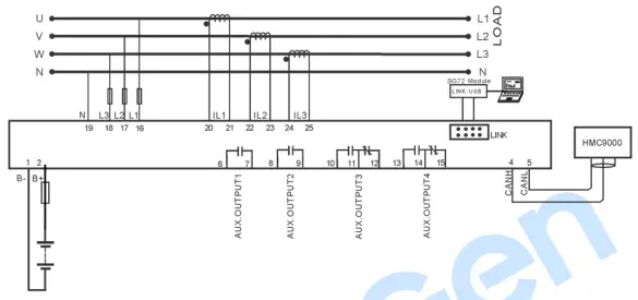
Fig.2 HMP300 Typical Application Diagram
DIFFERENTIAL CURRENT PROTECTION APPLICATION
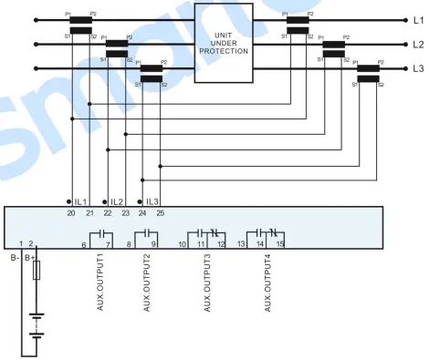
Fig.3 Differential Current Protection Application Diagram
NOTE: CTs on the two sides must have same parameter characteristics, and cable load on the two sides also must be equal.
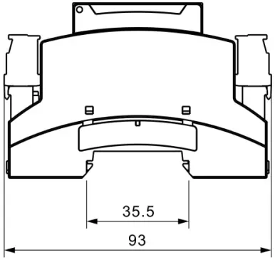
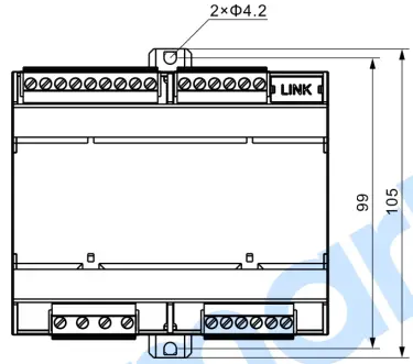
INSTALLATION
Fig.4 Overall and Cutout Dimensions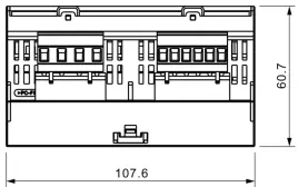
ATTENTION:
- OUTPUT AND EXPAND RELAYS
All outputs of controller are relay contact output type. If it needs to expand the relays, please add freewheel diode to both ends of expand relay’s coils (when coils of relay have DC current) or, increase resistance-capacitance return circuit (when coils of relay have AC current), inorder to prevent disturbanceB for controller or other equipments. - AC INPUT
Current input of controller must be connected to outside current transformer. And the current transformer’s secondary current must be 5A. At the same time, the phases of current transformer and input voltage must be correct. Otherwise, the collected current and active power may be not correct.
NOTE: When there is load current, transformer’s secondary side is prohibited to open circuit. - WITHSTAND VOLTAGE TEST
When controller has been installed on control panel, if it needs the high voltage test, please disconnect controller’s all terminal connections, in order to prevent high voltage going into controller and damaging it.
SmartGen
SmartGen — make your generator smart
SmartGenTechnology Co.,Ltd.
No.28 Jinsuo Road
Zhengzhou
Henan Province
P. R. China
Tel: +86-371-67988888/67981888/67992951
+86-371-67981000(overseas)
Fax: +86-371-67992952
Web: www.smartgen.com.cn
www.smartgen.cn
Email: [email protected]
All rights reserved. No part of this publicati


