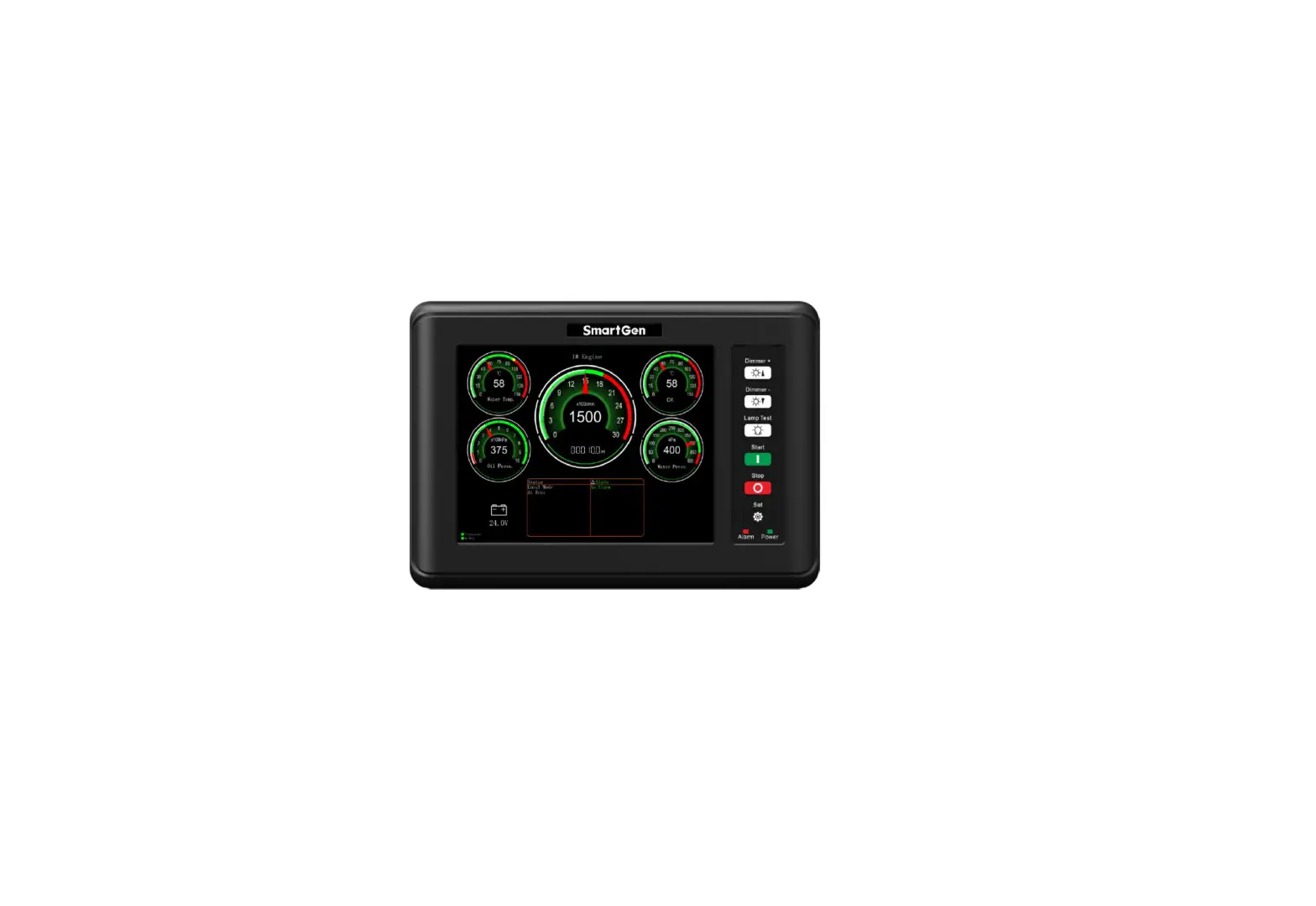
SmartGen HMC9800RM Remote Monitoring Controller
SmartGen — make your generator smart
Smart
G en Technology Co., Ltd
No. 28 Jinsuo Road
Zhengzhou City
P. R.
China
Tel:
0086-371-67988888
0086-371-67981888
0086-371-67991553
0086-371-67992951
0086-371-67981000 (overseas)
Fax: 0086 371 67992952
Web: www.smartgen.com.cn
www.smartgen.cn
Email: [email protected]
All rights reserved. No part of this publication may be reproduced in any material form (including photocopying or storing in any medium by electronic means or other) without the written permission of the copyright holder.
Applications for the copyright holder’s written permission to reproduce any part of this publication should be addressed to SmartGen Technology at the address above.
Any reference to trademarked product names used within this publication is owned by their respective companies.
SmartGen Technology reserves the right to change the contents of this document without prior notice.
Table 1Version History
| Date | Version | Content |
| 2018-09-20 | 1.0 | Original release |
OVERVIEW
HMC
9800 RM is a remote monitoring module for HMC4000 engine controller which is used for remote monitoring system of single unit to achieve remote start/stop marine engine, data measurement, alarm s display and etc. functions via RS485 port. Meters on the module can automatically synchronize the name and alarm threshold set by the HMC4000 controller, and each meter can set different ranges and data sources.
PERFORMANCE AND CHARACTERISTICS
Main features are as follows:
- 8 inch LCD with 800*600 resolution;
- Each meter s data source, range and resolution can be defined by users;
- Each meter s alarms display area can automatically synchronize alarm threshold set by t he
HMC4000 controller - Each meter s name can automatically synchronize sensor name set by the HMC4000 controller;
- Enable CANBUS communication and RS485 communication;
- With LCD brilliance level (5 levels) adjusting button, it is convenient to us e in differe nt occasion;
- This module must be used together with host controller;
- Widely power supply range 1 8~35 ) VDC to meet requirement of different voltage of start batteries;
- Modular design, embedded installation way; compact structure with easy mounting
TECHNIC AL PARAMETERS
Table 2 Technical Parameters
| Items | Content |
| Working Voltage | DC18.0V to DC35.0V, uninterrupted power supply. |
| Overall Power Consumption | <8W |
| RS485 Baud Rate | 9600bps |
| LCD Brightness | 5 levels can be adjustable |
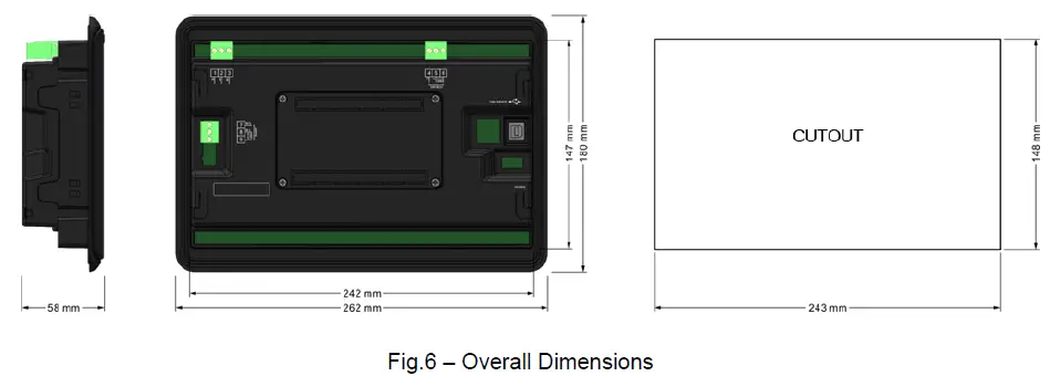
| Case Dimension | 262mm x 180mm x 58mm |
| Panel Cutout | 243mm x 148mm |
| Working Conditions | Temperature: (-25~+70)ºC; Relative Humidity: (20~93)%RH |
| Storage Conditions | Temperature: (-25~+70)ºC |
| Weight | 0.95kg |
OPERATION
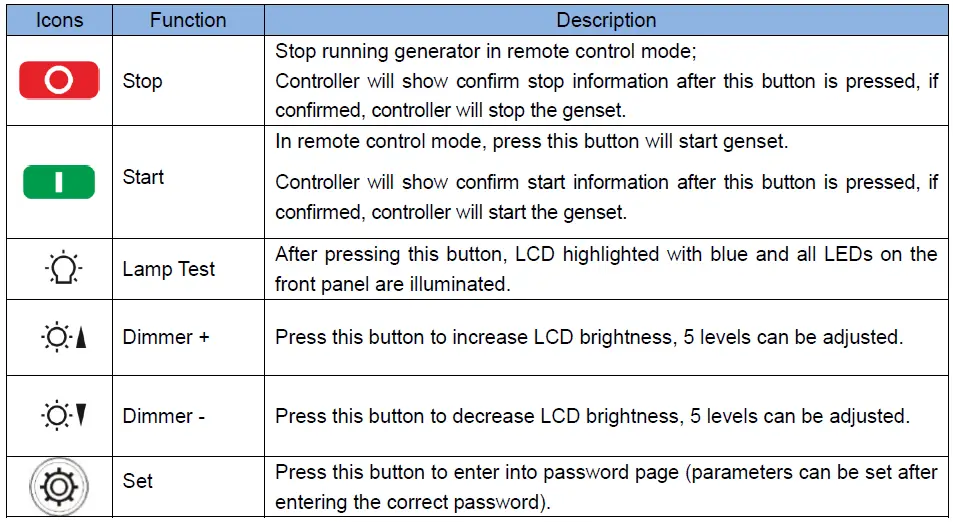
KEYS FUNCTION DESCRIPTION
Table 3– Push Buttons Descriptionescription:
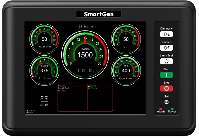
LCD DISPLAY
NO POWER DATA DISPLAY
All data displayed on HMC9800RM are real real-time collected from HMC4000 via RS485 port. Specific display screen is as below,
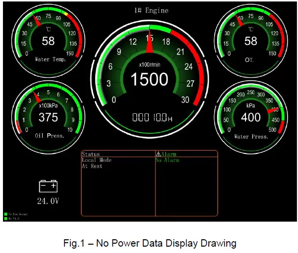
Meter: it is consist with 5 meters, an d each meter meter’s data source, range, and resolution can be configured. Each meter meter’s name and alarm threshold display area (red and yellow color area areas) will change with the settings of the HMC4000 controller.
For example, water temperature meter shows as below,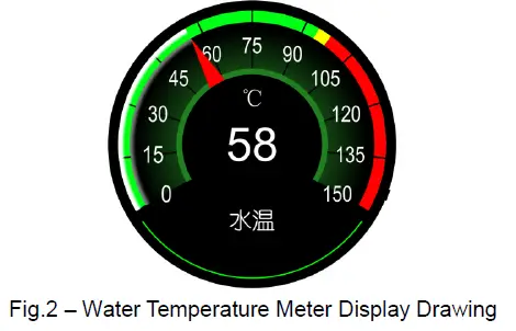
Data of this meter comes from sensor 1 data, name is water temperature. Display resolution is 1 1; alarm limit is 98 98℃; stop limit is 100 ℃.
b)Status : engine status and controller mode are real real-time displayed on this module.
c)Alarm: if no alarms occur, icon shows as white color; if warning alarms occur, both icon and alarm information display as yellow color; if shutdown alarms occur, both icon and alarm information display as red color.
d)Communication Indication: When the communication is normal, the TX icon and the RX icon flash alternately for 500ms; when the communication fails, the RX icon is grayed out and does not flash.
The communication status is displayed as a communication failure.
WITH POWER DATA DI SPLAY
All data displayed on HMC9800RM are real real-time collected from HMC4000 via RS485 port. Specific display screen is as below,
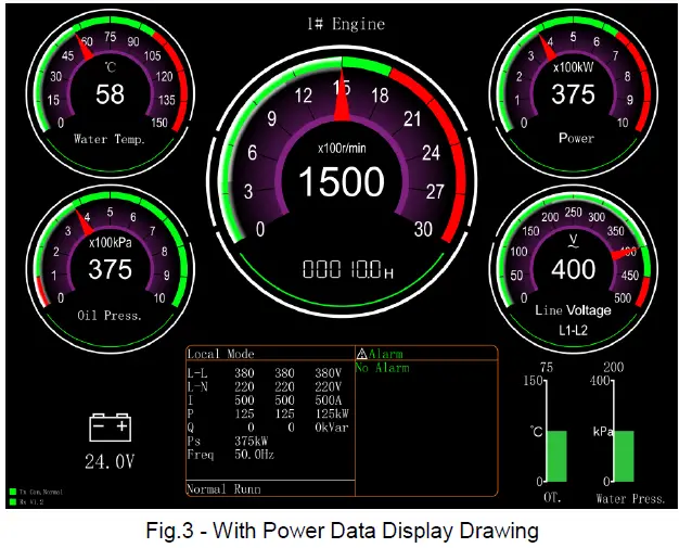
a)Battery: If any meter meter’s data comes from battery voltage, icon of battery on the left bottom will disappear automatically; otherwise, battery voltage will display on the left bottom.
b) Two columnar data sources can be selected from sensors 14 and the range is also selectable. It automatically disappears when select not to use it.
OPERATION
Press
Remote Mode button on HMC4000 panel, controller enters into remote mode. Users can remote start/stop engine via HMC9800RM controller after remote mode is active.
- Remote Start
Press of HGM9800RM, confirm information will display on LCD of the controller. After confirmed, controller initiate s start commend and countdown information of start pre-heat delay, safety on time, start idle delay, warming up time and etc. will displayed on LCD of the controller different engine co nfiguration with different display content
 - Remote Stop
Press of HGM9800RM , confirm information will display on LCD of the controller. After confirmed, controller initiates st op commend and countdown information of cooling delay, st op idle delay, ETS delay, wait for stop time and etc. will displayed on LCD of the controller (different engine configuration with different display content.
NOTE:
if alarms occur red during start/stop process, alarms information will synchronous display on the
LCD of HMC9800 RM.
PARAMETER CONFIGURATION
Display of 5 meters and 2 c olumnar tables can be configured by controller, details of parameter configuration is as below,
Table 4 Parameter Configuration List
| No. | Parameter Name | Range | Default | Remark | |
| 1. |
Meter 1 Set | Data Sources | 0-31 | 2: Sensor1 Data | Data source please to see Table 5 |
| 2. | Meter Range | 15-3000 | 150 | ||
| 3. | Resolution | 1-100 | 1 | ||
| 4. |
Meter 2 Set | Data Sources | 0-31 | 3: Sensor 2 Data | Data source please to see Table 5 |
| 5. | Meter Range | 15-3000 | 1000 | ||
| 6. | Resolution | 1-100 | 100 | ||
| 7. | Meter 3 Set | Data Sources | Fixed as speed | Fixed as speed | |
| 8. | Meter Range | 15-3000 | 3000 | ||
| 9. | Resolution | 1-100 | 100 | ||
| 10. | Meter 4 Set | Data Sources | 0-31 | 4: Sensor 3 Data | Data source please to see Table 5 |
| 11. | Meter Range | 15-3000 | 150 | ||
| No. | Parameter Name | Range | Default | Remark | |
| 12. | Resolution | 1-100 | 1 | ||
| 13. |
Meter 5 Set | Data Sources | 0-31 | 5: Sensor 4 Data | Data source please to see Table 5 |
| 14. | Meter Range | 15-3000 | 1000 | ||
| 15. | Resolution | 1-100 | 100 | ||
| 16. |
Meter 6 Set | Data Sources | 0-4 | 0: Not Used | Selectable range of meter 6 data source is sensor 1~ sensor 4. |
| 17. | Meter Range | 15-3000 | 1000 | ||
| 18. |
Meter 7 Set | Data Sources | 0-4 | 0: Not Used | Selectable range of meter 7 data source is sensor 1~ sensor 4. |
| 19. | Meter Range | 15-3000 | 1000 | ||
| 20. | Meter Color | 0~2 0: Green 1: Brown Red 2:Purple | 0: Green | This parameter can change display colors of the meter. It is active after re-power up. | |
| 21. | Genset No. Set | 1-9 | 1 | This parameter can configure which engine will be monitored. Main screen will display related genset number according to the setting. | |
Table 5 Data Source List
| No. | Data Source | Remark |
| 0. | Reserved | |
| 1. | Reserved | |
| 2. | Sensor 1 Data | |
| 3. | Sensor 2 Data | |
| 4. | Sensor 3 Data | |
| 5. | Sensor 4 Data | |
| 6. | Battery Supply | |
| 7. | Fuel Pressure(ECU) | |
| 8. | Reserved | |
| 9. | Reserved | |
| 10. | Generator UA | |
| 11. | Generator UB | |
| 12. | Generator UC |
| No. | Data Source | Remark |
| 13. | Generator UAB | |
| 14. | Generator UBC | |
| 15. | Generator UCA | |
| 16. | Frequency | |
| 17. | A Phase Current | |
| 18. | B Phase Current | |
| 19. | C Phase Current | |
| 20. | Reserved | |
| 21. | Reserved | |
| 22. | Reserved | |
| 23. | Total Power | |
| 24. | Reserved | |
| 25. | Reserved | |
| 26. | Reserved | |
| 27. | Reserved | |
| 28. | Reserved | |
| 29. | Reserved | |
| 30. | Reserved | |
| 31. | Reserved |
WIRING CONNECTION
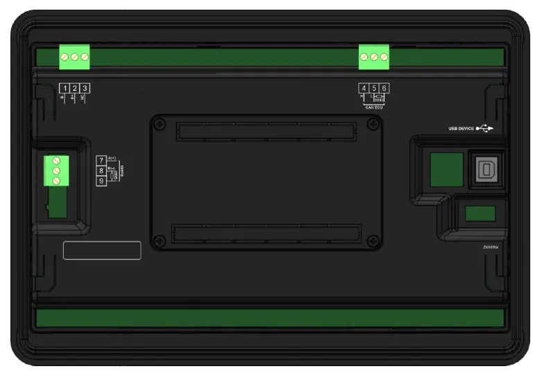
Fig.4 HMC9 800RM Terminals Drawing
Table 6 Terminals Wiring Connection Description
| No. | Function | Cable | Remark |
| 1 | B- | 1.0mm2 | Negative of DC power supply input |
| 2 | B+ | 1.0mm2 | Positive of DC power supply input |
| 3 | NC | Not connected | |
| 4 | CAN(H) | 0.5mm2 | It is CANBUS port which communicates with host controller; impedance-120Ω shielding wire is recommended with its single-end earthed. |
| 5 | CAN(L) | ||
| 6 | 120Ω | ||
| 7 | RS485(A+) | 0.5mm2 | It is CANBUS port which communicates with host controller; impedance-120Ω shielding wire is recommended with its single-end earthed. |
| 8 | RS485(B-) | ||
| 9 | 120Ω | ||
| USB | It is port to configurate parameters. | ||
TYPICAL APPLICATION
HMC9800RM communicates with HMC4000 via RS485 port. HMC4 HMC4000RM must be selected enabled on HMC4000 before communicartion. Details application is as below, 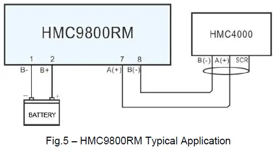
OVERALL AND INSTALLATION DIMENSIONS
TROUBLESHOOTING
Table 7– Troubleshooting
| Problem | Possible Solution |
| Controller no response with power. | Check controller connection wirings; |
| Communication failure | Check RS485 connection wirings. |
| Big error of meter data display | Check correctness of rated meter settings. |


