![]()
HRC200
INDUSTRIAL REMOTE CONTROL
USER MANUAL
SMARTGEN (ZHENGZHOU) TECHNOLOGY CO., LTD.
![]() Chinese trademark
Chinese trademark![]() English trademark
English trademark
SmartGen — make your generator smart
SmartGen Technology Co., Ltd.
No.28 Jinsuo Road
Zhengzhou
Henan Province
P. R. China
Tel: +86-371-67988888/67981888/67992951
+86-371-67981000(overseas)
Fax: +86-371-67992952
Email: [email protected]
Web: www.smartgen.com.cn /www.smartgen.cn
All rights reserved. No part of this publication may be reproduced in any material form (including photocopying or storing in any medium by electronic means or other) without the written permission of the copyright holder.
Applications for the copyright holder’s written permission to reproduce any part of this publication should be addressed to Smartgen Technology at the address above.
Any reference to trademarked product names used within this publication is owned by their respective companies.
SmartGen Technology reserves the right to change the contents of this document without prior notice.
Table 1 Software Version
Date | Version | Note |
| 2021-07-02 | 1.0 | Original release. |
1 OVERVIEW
HRC200 is a long-distance wireless remote control with LoRa wireless chip transmission and remote control distance of more than 200m. Used with engine controller, it can realize remote start, stop, load, unload, emergency stop and other functions. HRC200 adopts fully sealed structure, IP65 protection level, which can effectively prevent dust, water or others from entering the controller, making the controller operate stably and reliably, suitable for field, mining, urban construction and other application sites with complex working conditions.
2 PERFORMANCE AND CHARACTERISTICS
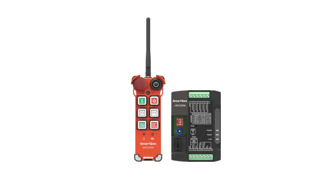
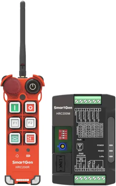
HRC200 industrial remote control is composed of remote control HRC200R and receiver HRC200M, applying LoRa wireless transmission chip.
Remote Control:
——Can realize remote start, stop, load, unload, emergency stop and other functions, indicate engine running/alarm, remote control battery, command send/receive status;
——Powered by 4 AA batteries;
——With remote control distance of more than 200m, 15 optional communication channels;
——Whole protection level can reach IP65.
Receiver:
——With RS485 interface, 5 output ports and 2 input ports, can control engine controller via RS485 interface or relay output port;
——With power, RS485, LoRa communication status indicator; 15 optional communication channels;
——Supply range DC (8~35)V;
——Can set its parameters via PC;
——Modular structure design, anti-flaming ABS plastic shell, light weight, compact structure and easy installation;
——Standard Π type 35mm guide rail installation or screw installation is applied.
3 SPECIFICATION
Table 2 Technical Parameters
Item | Contents |
| Remote Control HRC200R | |
| Working Voltage | Powered by 4 AA alkaline batteries. |
| Overall Consumption | Can last about 72 hours. |
| Case Dimension (LxWxH) | 156.9mmx63mmx53mm (without antenna) |
| Working Conditions | Temperature: (-25~+70)°C Humidity: (20~95)%RH Actual working temperature is limited by battery characteristics. |
| Storage Condition | Temperature: (-30~+80)°C |
| Weight | 0.2kg (without battery) |
| Receiver HRC200M | |
| Working Voltage | DC (8~35)V |
| Overall Consumption | ≤1.2W |
| Aux. Input Port | B- connected is active. |
| Aux. Output Port | Relay normally open volt-free output, specification DC30V/2A |
| RS485 Interface | Isolated, half-duplex, 2400/4800/9600/19200 baud rate can be set, Modbus-RTU communication protocol, longest communication distance 1,000m. |
| LINK | SmartGen special interface for program upgrade. |
| Case Dimension (LxWxH) | 105mmx72.5mmx34mm |
| Working Conditions | Temperature: (-25~+70)°C Humidity: (20~95)%RH |
| Storage Condition | Temperature: (-30~+80)°C |
| Weight | 0.2kg |
4 PANEL AND WIRING TERMINAL DESCRIPTION
4.1 HRC200R REMOTE CONTROL PANEL INDICATORS AND KEYS
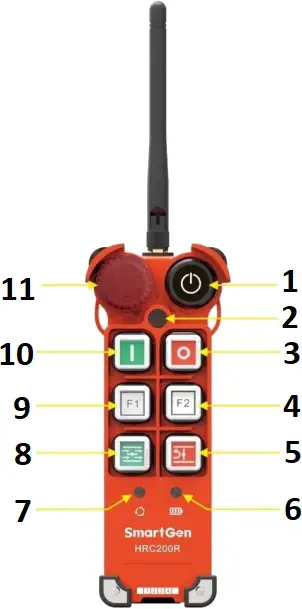
Fig.1 Remote Control Panel Description
- Power Key
- Connection Status Indicator
- Stop Key
- F2 Key
- Unload Key
- Power Status Indicator
- Common Alarm/Running Status Indicator
- Load Key
- F1 Key
- Start Key
- Emergency Stop Key
Table 3 Indicators Description
Indicators | Description |
Power Status | Indicator flashes yellow during pairing process; Indicator keeps red on when battery voltage is low; it keeps green on when battery voltage is normal. |
Connection Status | Indicator flashes yellow during pairing process; Press the key, indicator flashes red once when sending, indicator flashes green once when receiving success; Indicator displays yellow when communication abnormal situation lasts over 5s; indicator flashes yellow once after pressing the key. |
Common Alarm/Running Status | Indicator flashes yellow during pairing process; Indicator keeps green on during normal running; Indicator flashes red when common alarm occurs; It will extinguish when communication abnormal situation lasts over 5s. |
Table 4 Keys Description
Icon | Key | Description |
 | Power | Long press this key 2s to power on the remote control, then long press this key 2s again to power off the remote control. |
 | Start | Press this key to send start command. |
 | Stop | Press this key to send stop command. |
 | F1 | Press this key to send F1 command. (see the following description.) |
 | F2 | Long press this key 6s to enter pairing, press it again during the pairing process to cancel pair; Press this key to send F2 command. (see the following description.) |
 | Load | Press this key to send load command. |
 | Unload | Press this key to send unload command. |
 | Emergency Stop | Press this key to send emergency stop command, turn it clockwise to reset. (When this key is pressed, load/unload/start/F1/F2 keys are all inactive, communication status indicator keeps flashing red.) |
No Key Operation | If can’t receive the data and no key operation within 10 minutes, remote control power will automatically shut off. |
4.2 HRC200M RECEIVER PANEL INDICATORS AND INTERNAL KEYS
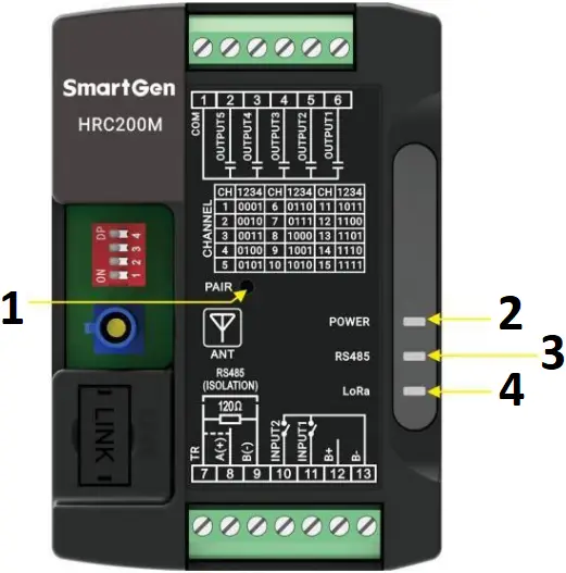
Fig.2 Receiver Panel Description
- Pair Key
- Power Status Indicator
- RS485 Communication Status Indicator
- LoRa Communication Status Indicator
Table 5 Indicators and Keys Description
Indicator | Description |
| POWER (Indicator: green) | Always illuminating: power is normal; Always extinguishing: power is abnormal. |
| RS485 (Indicator: green) | Flashing: RS485 communication is normal; Always extinguishing: RS485 communication fails. |
| LoRa (Indicator: green) | Flashing: communication with remote control is normal; Always extinguishing: communication with remote control fails. |
| PAIR (key) | Long press it 6s to enter pairing mode; Press it again after entering pairing mode can cancel pair. |
4.3 COMMUNICATION CHANNEL CONFIGURATION
The remote control configures the communication channel via jumper cap. Jumper cap leftmost and rightmost positions are inactive, it is 1 when the middle four positions are connected to the jumper cap, otherwise it is 0. The default jumper cap position is 1111 (515MHz).
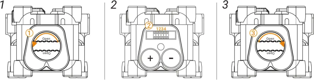
Fig.3 Communication Channel Configuration
Table 6 Communication Channel Configuration Steps
Step | Description |
1 | Turn the bottom screw cover anticlockwise to open the base. |
2 | Change the middle four jumper cap positions to configure the communication channel and replace the battery at the same time. |
3 | Turn the bottom screw cover clockwise to close the base. |
The receiver configures the communication channel via dial switch. It is 1 when the dial switch is set to ON position, otherwise it is 0. The default dial switch position is 1111 (515MHz).
Table 7 Communication Channels
No. | 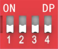 | Channel Frequency (MHz) |
1 | 0001 | 445 |
| 2 | 0010 | 450 |
3 | 0011 | 455 |
| 4 | 0100 | 460 |
5 | 0101 | 465 |
| 6 | 0110 | 470 |
7 | 0111 | 475 |
| 8 | 1000 | 480 |
9 | 1001 | 475 |
| 10 | 1010 | 485 |
11 | 1011 | 490 |
| 12 | 1100 | 495 |
13 | 1101 | 500 |
| 14 | 1110 | 505 |
15 | 1111 | 515 |
| It is 1 when the dial switch is set to ON position, otherwise it is 0. | ||
NOTE: When the dial switch is configured as 0000, it is configuration mode (refer to 4.1).
4.4 PAIRING
Table 8 Pairing Description
Method | Process |
| Method 1: Remote control waits for receiver pairing. | 1. Turn the remote control and receiver to the same channel. (see the communication channel configuration, default channel is 515MHz.) |
| 2. Turn on the remote control power, its power indicator keeps on. Long press F2 key 6s, all indicators are flashing yellow, which means entering pairing mode. Press F2 key again during LoRa pairing can cancel pair. | |
| 3. Turn on the receiver power, POWER indicator keeps on. Insert a slender needle less than 3.5mm in diameter into the PAIR hole vertically, then long press PAIR key 6s. | |
| 4. If pairing successfully within 60s, remote control COMM indicator extinguishes after illuminating green 2s, receiver LoRa and RS485 indicators extinguish, POWER indicator keeps green for a long time. Otherwise, COMM indicator keeps red for a long time when the pairing fails. | |
| Method 2: Receiver waits for remote control pairing. | 1. Turn the remote control and receiver to the same channel. (see the communication channel configuration, default channel is 515MHz.) |
| 2. Turn on the receiver power, POWER indicator keeps on. Insert a slender needle less than 3.5mm in diameter into the PAIR hole vertically, then long press PAIR key 6s, LoRa, RS485 and POWER indicator flash green. Press PAIR key again during LoRa pairing can cancel pair. | |
| 3. Turn on the remote control power, its power indicator keeps on. Long press F2 key 6s. | |
| 4. If pairing successfully within 60s, remote control COMM indicator extinguishes after illuminating green 2s, receiver LoRa and RS485 indicators extinguish, POWER indicator keeps green for a long time. Otherwise, COMM indicator keeps red for a long time when the pairing fails. |
4.5 RS485 INTERFACE
Receiver connects to engine controller via RS485 interface, 120 terminal matching resistor is recommended to use (when RS485 A(+) and TR terminal is short connected), RS485 communication line must use twisted shielded pair line.

Fig.4 RS485 Connection Diagram
4.6 RECEIVER WIRING TERMINAL
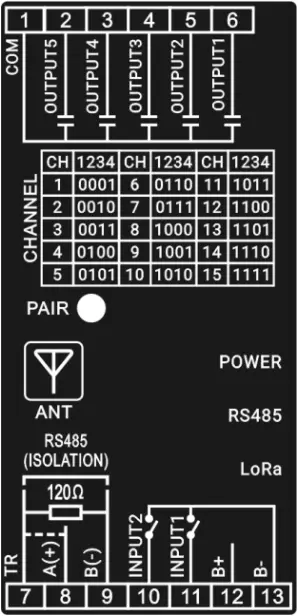
Fig.5 Mask Diagram
Table 9 Wiring Terminal Description
No. | Function | Cable Size | Remark |
1 | COM | 0.75mm² | Relay common port. |
2 | AUX. OUTPUT5 | 0.75mm² | Normally open volt-free output, capacity DC30V/2A. |
3 | AUX. OUTPUT4 | 0.75mm² | Normally open volt-free output, capacity DC30V/2A. |
4 | AUX. OUTPUT3 | 0.75mm² | Normally open volt-free output, capacity DC30V/2A. |
5 | AUX. OUTPUT2 | 0.75mm² | Normally open volt-free output, capacity DC30V/2A. |
6 | AUX. OUTPUT1 | 0.75mm² | Normally open volt-free output, capacity DC30V/2A. |
7 | TR | / | RS485 communication line uses twisted shielded pair line. When 120Ω terminal matching resistor is required, A(+) and TR terminal should be short connected. |
8 | RS485 A(+) | 0.5mm² | |
9 | RS485 B(-) | 0.5mm² | |
10 | AUX. INPUT2 | 0.75mm² | B- connected is active. |
11 | AUX. INPUT1 | 0.75mm² | B- connected is active. |
12 | B+ | 0.75mm² | Externally connects power positive. |
13 | B- | 0.75mm² | Externally connects power negative. |
5 PROGRAMMABLE PARAMETERS
5.1 PC PARAMETER SETTING
Before operation, please remember the dial switch position of HRC200M, then set switch to configuration mode (namely 0000 position). PC connects to receiver via RS485 communication conversion module, then the related parameter configuration of receiver can be done via PC software. After the configuration is completed, dial switch must recover to previous position.
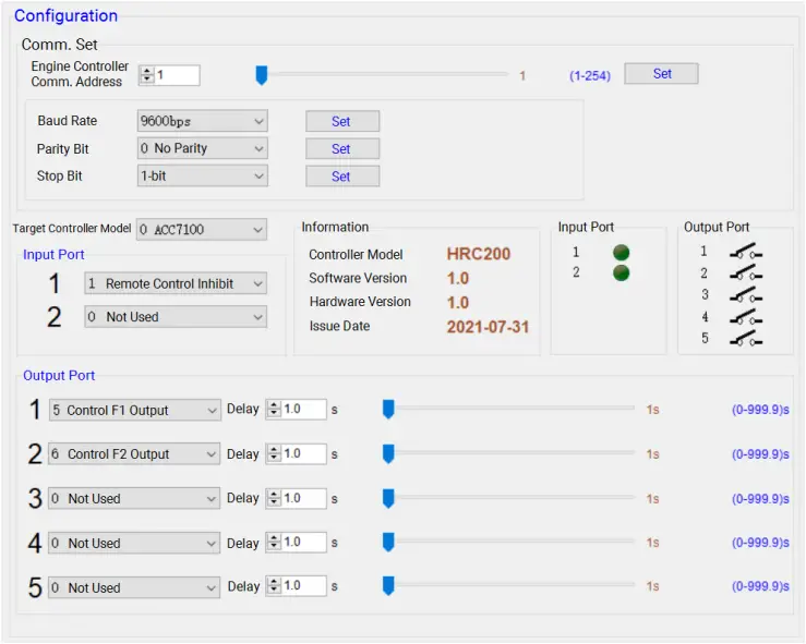
Fig.6 PC Configuration Interface
5.2 PARAMETER RANGE AND DEFINITION
Table 10 Parameter Content and Range
No. | Item | Range | Default | Description |
1 | Comm. Address | 1-254 | 1 | |
2 | Baud Rate | (0-3) | 2 | 0: 2400bps 1: 4800bps 2: 9600bps 3: 19200bps |
3 | Parity Bit | (0-2) | 0 | 0: No Parity 1: Odd Parity 2: Even Parity |
4 | Stop Bit | (0-1) | 0 | 0: 1-bit 1: 2-bit |
5 | Aux. Input 1 | (0-9) | 1 | 0: Not Used 1: Remote Control Inhibit 2: Simulate Start Key 3: Simulate Stop Key 4: Simulate Unload Key 5: Simulate Load Key 6: Simulate F1 Key 7: Simulate F2 Key 8: Simulate Running Status 9: Simulate Alarm Status |
6 | Aux. Input 2 | (0-9) | 0 | |
7 | Aux. Output 1 | (0-6) | 5 | 0: Not Used 1: Start Control 2: Stop Control 3: Unload Control 4: Load Control 5: F1 Control 6: F2 Control |
8 | Aux. Output 2 | (0-6) | 6 | |
9 | Aux. Output 3 | (0-6) | 0 | |
10 | Aux. Output 4 | (0-6) | 0 | |
11 | Aux. Output 5 | (0-6) | 0 | |
12 | Aux. Output 1 Output Delay | (0-999.9)s | 1.0s | When it is set as 0, relay continuously outputs when the remote control key is firstly pressed, relay stops output when the key is pressed again. When it is set as other values, relay disconnects output after outputting set delay value. |
13 | Aux. Output 2 Output Delay | (0-999.9)s | 1.0s | |
14 | Aux. Output 3 Output Delay | (0-999.9)s | 1.0s | |
15 | Aux. Output 4 Output Delay | (0-999.9)s | 1.0s | |
16 | Aux. Output 5 Output Delay | (0-999.9)s | 1.0s |
6 SYSTEM APPLICATION DIAGRAM
Remote control communicates with receiver via LoRa, engine controller and receiver can be controlled by RS485 communication or digital input/output port.
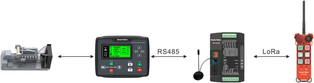
Fig.7 HRC200 System Application Diagram
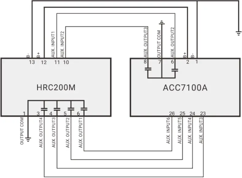
Fig.8 HRC200M Digital Control Application Diagram
Table 11 Parameter Configuration
No. | Item | Parameter | |
HRC200 | 1 | Aux. Input 1 | 8: Running Status |
2 | Aux. Input 2 | 9: Alarm Status | |
3 | Aux. Output 1 | 2: Stop Control | |
4 | Aux. Output 2 | 4: Load Control | |
5 | Aux. Output 3 | 3: Unload Control | |
6 | Aux. Output 4 | 1: Start Control | |
ACC7100A | 1 | Aux. Output 2 | 38: Start Success Output |
2 | Aux. Output 3 | 42: Common Alarm | |
3 | Aux. Input 3 | 34: Simulate Stop Key | |
4 | Aux. Input 4 | 35: Simulate Load Key | |
5 | Aux. Input 5 | 36: Simulate Unload Key | |
6 | Aux. Input 6 | 37: Simulate Start Key |
7 OVERALL AND INSTALLATION DIMENSIONS
7.1 REMOTE CONTROL OVERALL DIMENSION
Unit: mm
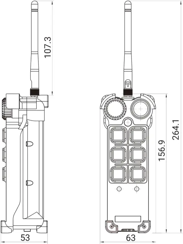
Fig.9 HRC200R Overall Dimension
7.2 RECEIVER OVERALL DIMENSION
Installation method can be 35mm guide rail installation or screw (M4) installation. Overall dimension is as follows:
Unit: mm
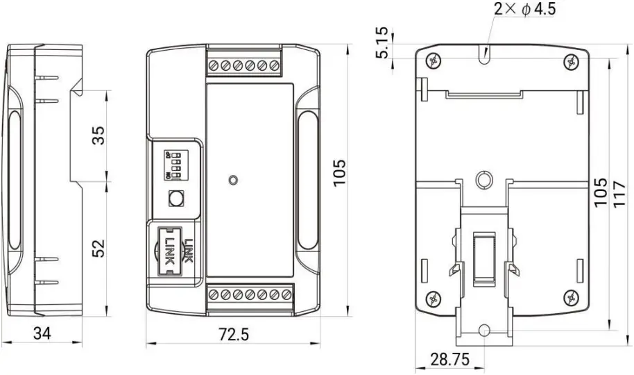
Fig.10 HRC200M Overall Dimension
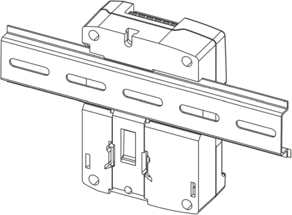
Fig.11 HRC200M Guide Rail Installation
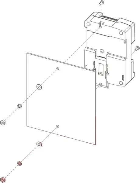
Fig.12 HRC200M Screw Installation
8 TROUBLESHOOTING
Table 12 Troubleshooting
Symptom | Possible Solutions |
| Receiver Inactive for Power | Check the power supply. |
| RS485 Comm. Abnormal | Check the connection line; Check whether communication address, baud rate, parity bit, stop bit set is correct; Check whether A(+) and B(-) of RS485 are reversely connected; Try to connect 120Ω terminal matching resistor. |
| Pairing Failure | Check whether the channel of remote control and receiver is same. |
| Receiver and PC Fails to Connect | Check whether the receiver dial switch is set to 0000 position. |
| Remote Control Key Inactive | Check whether the emergency stop key is pressed, when it is pressed, other function keys are inactive. |
__________________________
HRC200 Industrial Remote Control User Manual


