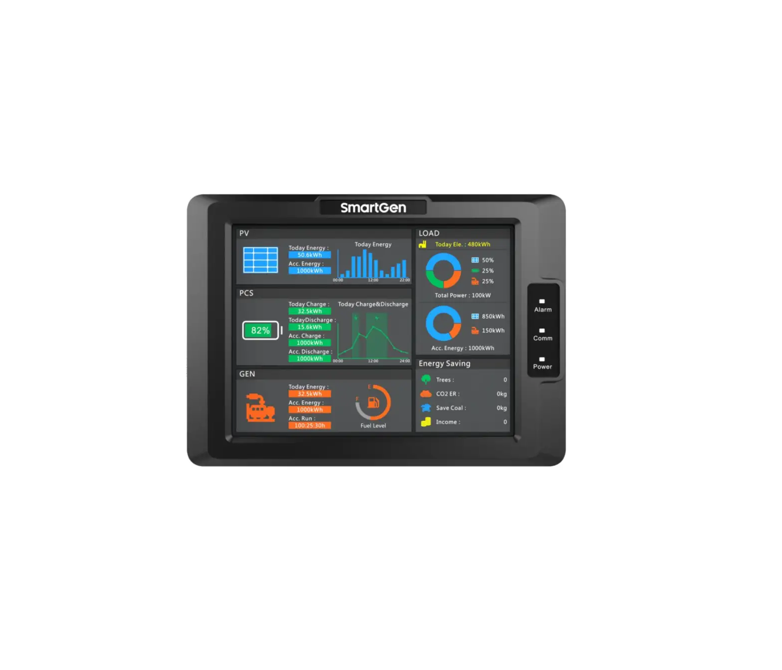
SmartGen HMU8-9570 Hybrid Energy Controller
![]() Chinese trademark
Chinese trademark![]() English tradema
English tradema
SmartGen — make your generator smart
SmartGen Technology Co., Ltd.
No.28 Jinsuo Road, Zhengzhou, Henan Province, China
Tel: +86-371-67988888/67981888/67992951 | +86-371-67981000(overseas)
Fax: +86-371-67992952
Web: www.smartgen.com.cn/ | www.smartgen.cn/
Email: [email protected]
All rights reserved. No part of this publication may be reproduced in any material form (including photocopying or storing in any medium by electronic means or other) without the written permission ofthe copyright holder.
Applications for the copyright holder’s written permission to reproduce any part of this publicationshould be addressed to SmartGen Technology at the address above. Any reference to trademarked product names used within this publication is owned by their respective companies.
SmartGen Technology reserves the right to change the contents of this document without prior notice.
Table 1 Software Version
| Date | Version | Note |
| 2021-10-09 | 1.0 | Original release. |
| 2022-06-11 | 1.1 | Change manual logo. |
Table 2 Symbol Instruction
| Symbol | Instruction |
| Highlights an essential element of a procedure to ensure correctness. | |
| Indicates a procedure or practice, which, if not strictly observed, could result in damage or destruction of equipment. | |
| Indicates a procedure or practice, which could result in injury to personnel or loss of life if not followed correctly. |
OVERVIEW
HMU8-9570 Hybrid Energy Controller is used for micro grid management system composed of solar energy, wind energy, energy storage battery and genset, which can monitor data via RS485 port. It can also control the start and stop of gensets in system according to load or storage battery SOC, and control output power by setting genset voltage, frequency center point and droop percentage. In addition, it has economy and power maintaining running modes.
HMU8-9570 Hybrid Energy Controller applies 8-inch 800*600 resolution capacitive touch screen with Chinese and English display. It is simple to operate and reliable to run
PERFORMANCE AND CHARACTERISTICS
HUM8-9570 hybrid energy controller can be used for data monitoring and control of inverter, converter and genset, which is suitable for micro grid hybrid energy system composed of photovoltaic, storage energy and genset, also for hybrid energy system composed of storage energy and genset. Main characteristics are as bellow:
- Display module adopts 8-inch LCD screen with 800×600 resolution, HMI display, capacitive touch screen operation. Optional Chinese and English interface can be chosen on site, making commissioning convenience for factory personnel;
- With power indicator, communication indicator and alarm indicator;
- The module has 10-level brightness, can be adjusted according to different environments;
- The homepage of display module can display PV current day power bar chart, current day charge/discharge curve diagram of energy storage battery, load power and accumulated energy pie chart;
- Display energy-saving and emission reduction parameters;
- Set genset frequency, voltage center point and droop percentage;
- Set RS485 communication port parameters on the module, which cannot be lost even in case of power outage. All module parameters can be adjusted through upper computer software via PC;
- Two running modes: economy and power maintaining;
- With 4 RS485 ports, 1 CANBUS port, 1 ETHERNET port;
- Displayed photovoltaic inverter parameters:
Table 3 Photovoltaic Inverter Parameters
| Name | Unit | Name | Unit |
| PV Working Status | / | PV Output Active Power | kW |
| PV Today Accumulated Generating Power | kWh | PV Output Reactive Power | kvar |
| PV Accumulated | kWh | PV Output Frequency | Hz |
| PV Input Voltage | V | PV Phase Voltage | V |
| PV Input Current | A | PV 3-phase Current | A |
| PV Input Power | kW | PV Power Factor | / |
- Displayed converter parameters:
Table 4 Converter Parameters
| Name | Unit | Name | Unit |
| Working Mode | / | Reactive Power | kvar |
| Working Status | / | Battery Status | / |
| Daily Grid-connected Run Time | min | Daily Charge | kWh |
| Total Grid-connected Run Time | h | Daily Discharge | kWh |
| Battery Voltage | V | Total Charge | kWh |
| Battery Current | A | Total Discharge | kWh |
| Battery Power | kW | Daily Battery Charge Time | min |
| Power Grid Frequency | Hz | Daily Battery Discharge Time | min |
| Line Voltage | V | Total Battery Charge Time | h |
| 3-phase Current | A | Total Battery Discharge Time | h |
| Power Factor | / | Battery SOC | % |
| Active Power | kW |
- Displayed genset parameters:
Table 5 Genset Parameters
| Name | Unit | Name | Unit |
| Genset Mode | / | Each Phase Active Power | kW |
| Genset Working Status | / | Total Active | kW |
| Genset Accumulated Run Time | min | Each Phase Reactive Power | kvar |
| Genset Today Generating Power | kWh | Total Reactive Power | kvar |
| Genset Total Generating Power | kWh | Each Phase Apparent Power | kVA |
| Gen 3-phase Phase Voltage | V | Each Phase Power Factor | / |
| Gen 3-phase Line Voltage | V | Average Power Factor | / |
| Gen Frequency | Hz | Fuel Level | % |
- Wide power supply range DC(10~35)V, suitable for different starting battery voltage environment;
- USB equipment port for upgrading display module firmware;
- USB master port for upgrading screen picture and word stock of display module;
- IP65 waterproof level is achieved with the help of rubber-ring gasket between shell and control panel;
- Controller is fixed by metal clips;
- Modular structure design, pluggable terminal, built-in mounting, compact structure with easy installation.
SPECIFICATION
Table 6 Technical Specification
| Parameter | Details |
| Working Voltage | Range: DC10V~DC35V, DC reverse connection protection |
| Overall Consumption | <6W |
| RS485 | Isolated, half-duplex, 9600/19200/38400/57600/115200bps baud rate, maximum communication length 1000m (under 9600bps). |
| Ethernet | Self-adapting 10/100Mbit |
| CAN BUS | Isolated, maximum communication length 250m; use Belden 9841 cable or equivalence. |
| Vibration Test | 5-8Hz: ±7.5mm 8-500Hz: 2g IEC 60068-2-6 |
| Shock Test | 50g, 11ms, half-sine, complete shock test from three directions, and 18 times shock for each test IEC 60068-2-27 |
| Bump Test | 25g, 16ms, half-sine IEC 60255-21-2 |
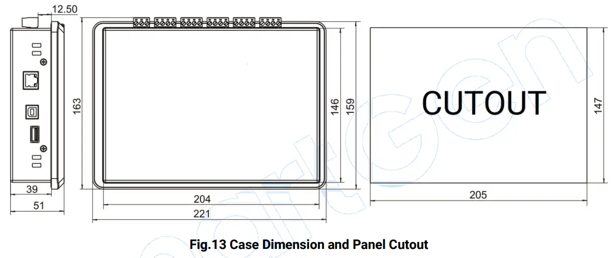
| Case Dimensions | 221mm x 163mm x 51mm |
| Panel Cutout | 205mm x 147mm |
| Working Temperature | (-25~+70)°C |
| Working Humidity | (20~93)%RH |
| Storage Temperature | (-30~+80)°C |
| Protection Level | Front Enclosure: IP65 when rubber-ring gasket is installed between the enclosure and the control panel Rear Enclosure: IP20 |
| Weight | 1.3kg |
OPERATION
CONTROLLER PANEL
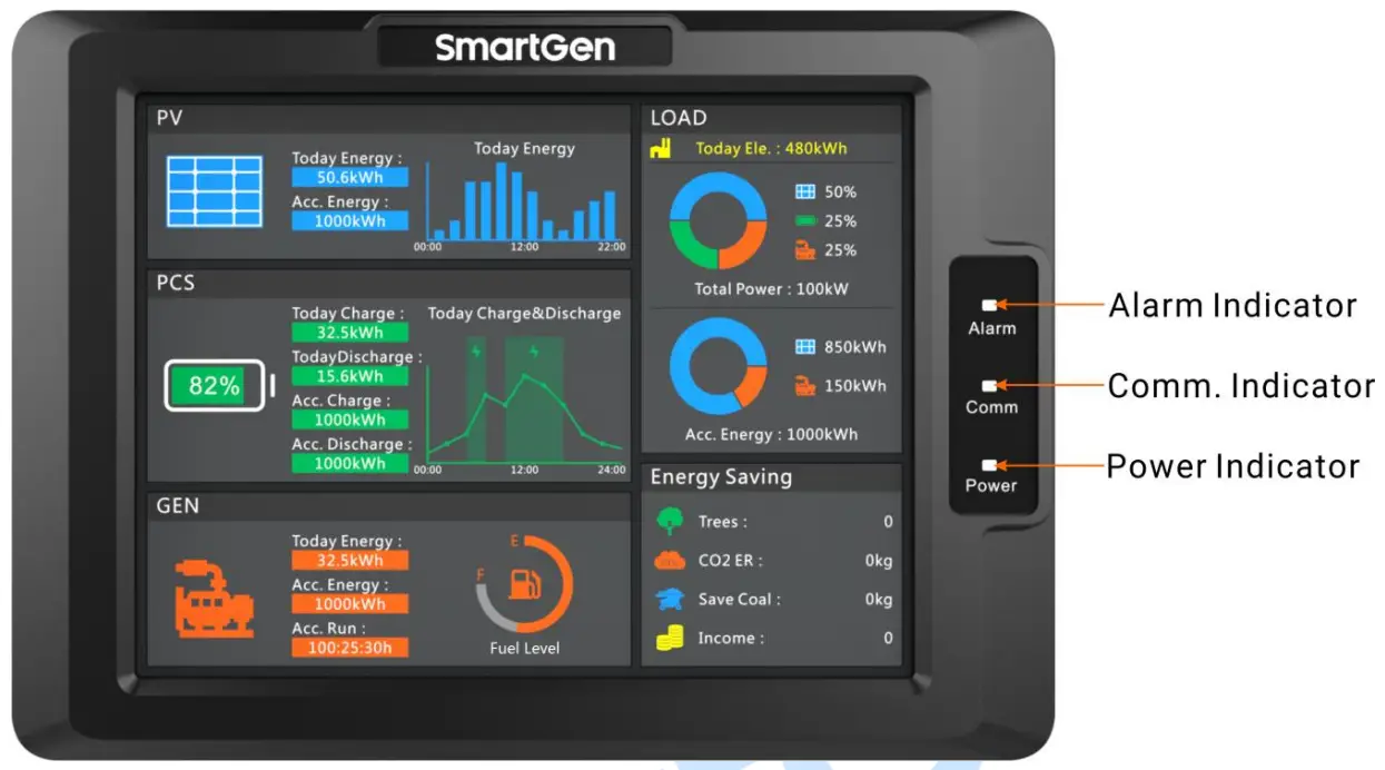
Fig.1 HMU8-9570 Indication
Table 7 Indicators Description
| Indicator | Description |
| Alarm Indicator | Warning alarm: slow flashes (1 time/s); Fault alarm: fast flashes (5 times/s); No alarm: extinguishes. |
| Comm. Indicator | It always illuminates when controller communicates with inverter, converter, genset normally; It extinguishes when communication is abnormal. |
| Power Indicator | It always illuminates after controller is powered on and working; It extinguishes after controller stops working. |
![]() NOTE: Mute the sounds by sliding touch screen.
NOTE: Mute the sounds by sliding touch screen.
DISPLAY INTERFACE AND OPERATION
ILLUSTRATION
The controller has 6 interfaces, including homepage, photovoltaic, PCS, genset, load and setting. The interface can be switched by sliding the touch screen.
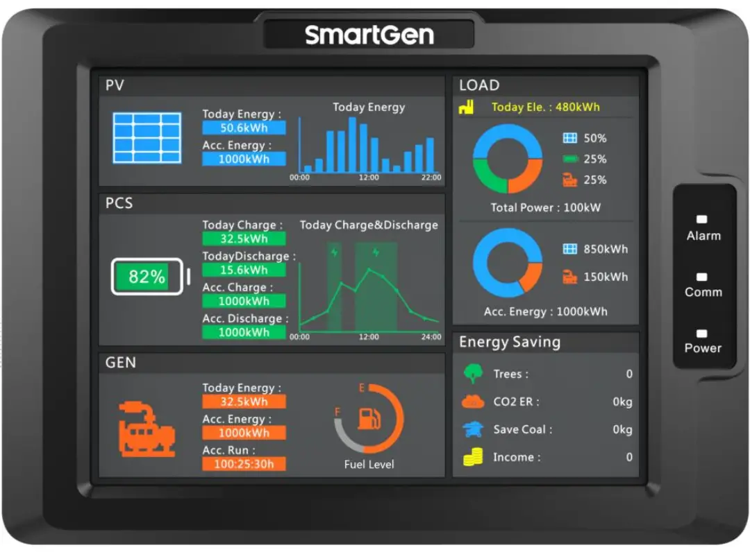
HOMEPAGE INTERFACE
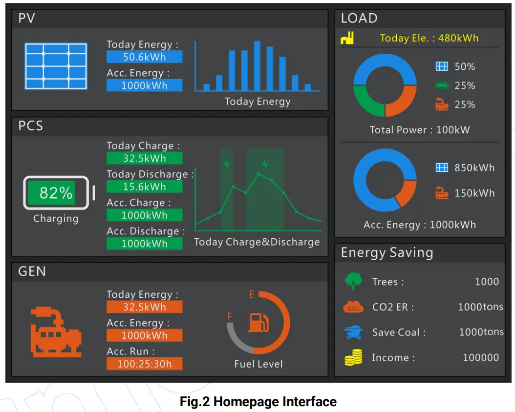
This interface displays some parameter information of photovoltaic, energy storage battery, genset, load, energy saving and emission reduction. When photovoltaic inverter, energy storage converter and genset have alarm information, alarm information will be displayed in corresponding title bar.
PV INTERFACE
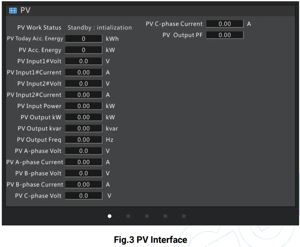
This interface displays working status of photovoltaic inverter, accumulated generating power, input DC voltage, current, output AC voltage, current information.
PCS INTERFACE
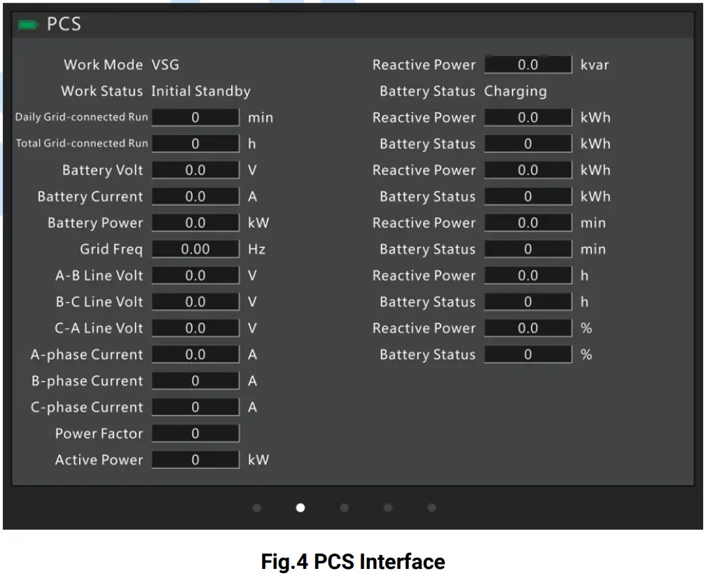
This interface displays converter working mode, working status, running time, battery pack information, output AC voltage, current, power, etc
GENSET INTERFACE
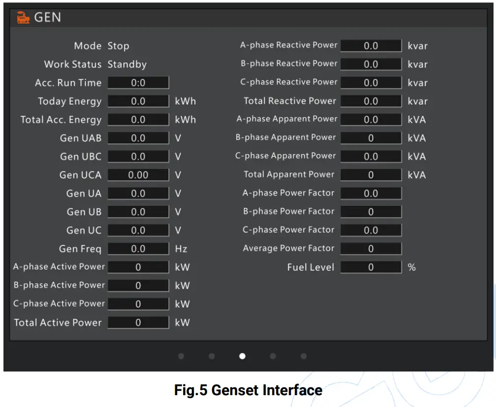
This interface displays genset controller mode, working status, running time, generating power, output AC voltage, current, power, etc.
LOAD INTERFACE
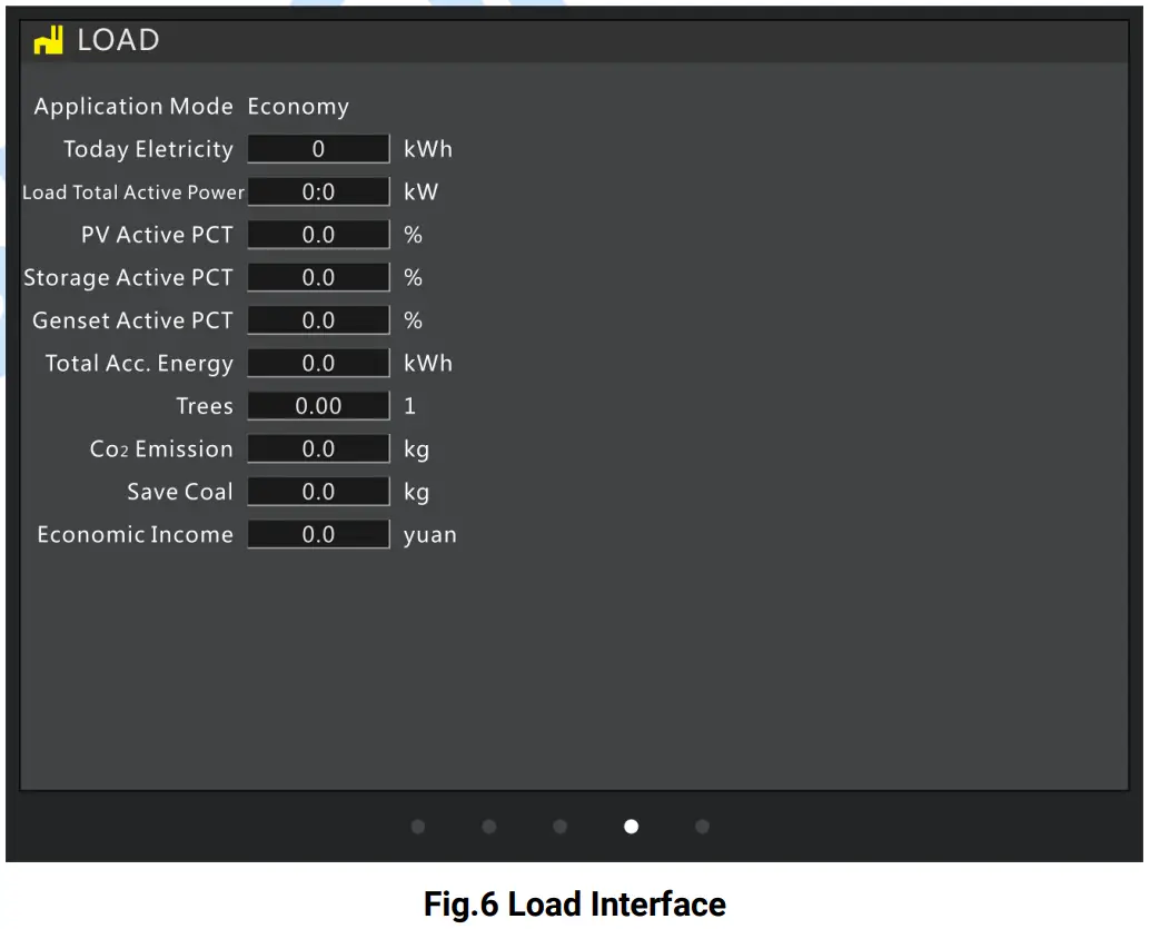
This interface displays system application model, power consumption, energy saving and emission reduction, etc.
SETTING INTERFACE
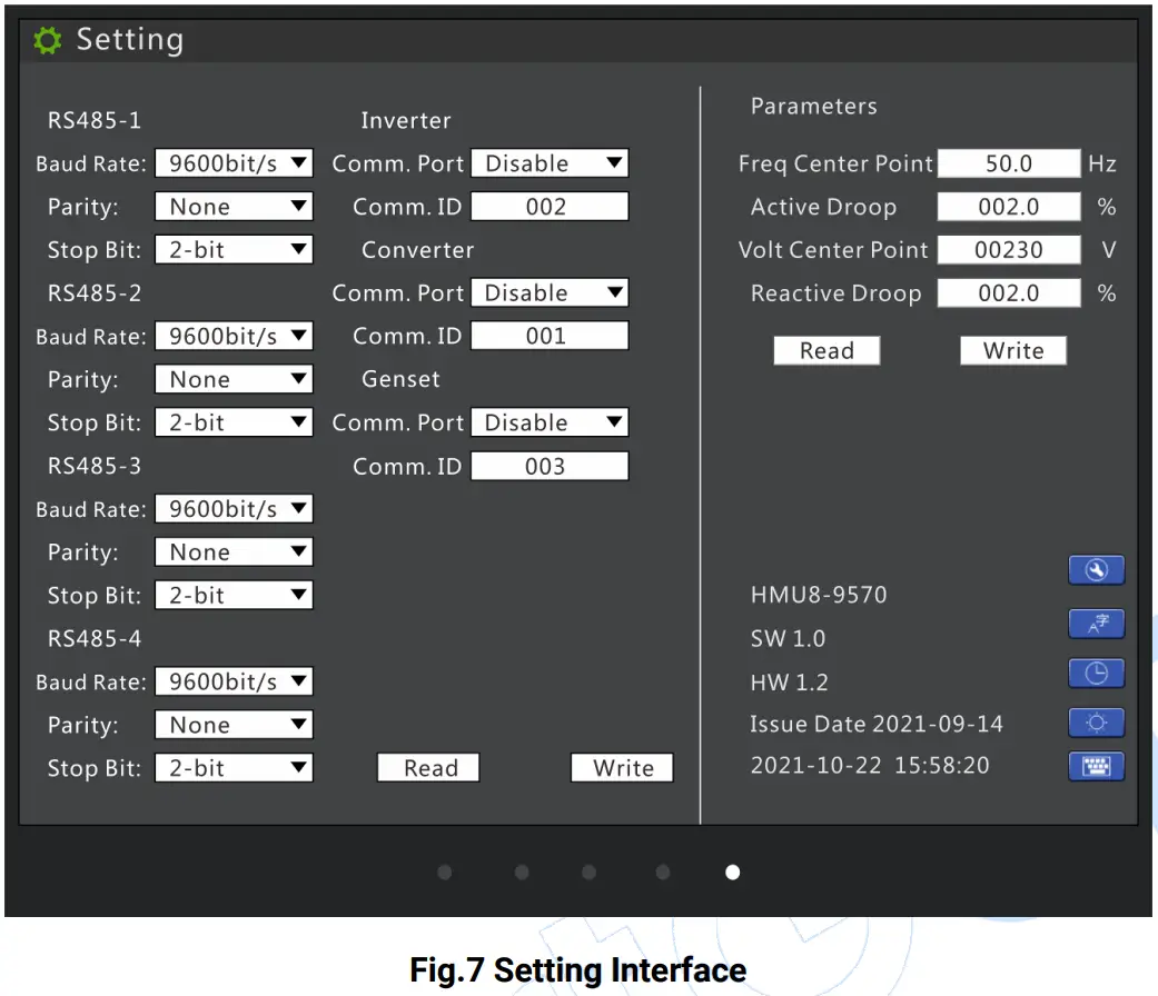
Table 8 Key Description
| Icon | Key | Description |
 | Parameter Setting | Press it, accumulated information can be cleared by inputting password. |
 | Language | Press it can set display module language as Chinese or English. |
 | Date and Time | Press it can set module date and time. |
 | Brightness | Press it can adjust module screen brightness and make lamp test, time is 2s. |
 | Numeric Keypad | When the parameter needs to be changed, press it can pop up numeric keypad. |
Controller parameter setting steps:
- Select parameter items need to be configured;
- Parameters with parameter list boxes selects corresponding configurations by clicking the list;
- If you want to change the parameter of text box, please press the numeric keypad to pop up it;
- Click “Write” button, parameter save dialog box will pop up, then save parameters according to hints.
![]() NOTE: Controller password needs to be inputted when configuring parameters, then you can save parameters
NOTE: Controller password needs to be inputted when configuring parameters, then you can save parameters
RUNNING MODE DESCRIPTION
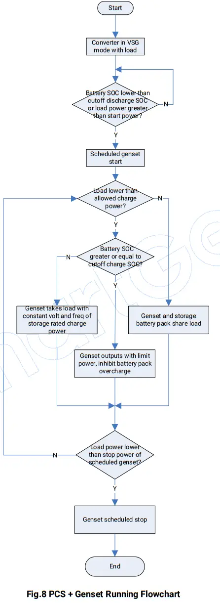
PCS + GENSET SYSTEM
PCS supplies power for load in VSG (Virtual Synchronous Genset) mode. When storage loading power is greater than start power of scheduled genset or battery pack SOC is lower than cutoff discharge SOC, genset will start. If genset and storage battery pack share the load, when load power is lower than allowed storage charge power, genset will charge the battery pack with constant voltage and frequency of storage rated charge power. When battery pack SOC is greater than cutoff charge SOC, genset will not charge for battery pack, genset and storage battery pack share the load (NOTE: Converter droop and genset droop should be set as same). When load power is lower than stop power of scheduled genset, genset will stop.
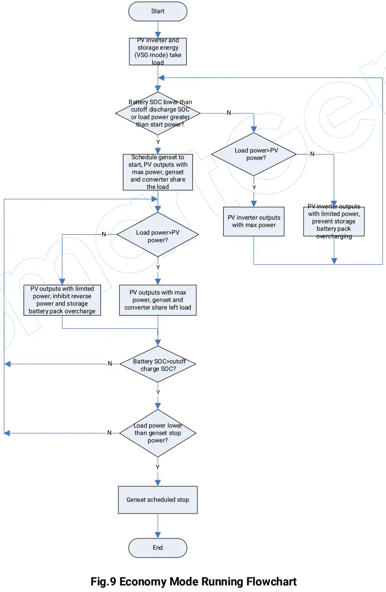
PV + PCS + GENSET SYSTEM
- ECONOMY MODE
If solar energy and storage energy supply power for load, when storage power is greater than start power of scheduled genset or battery pack SOC is lower than cutoff discharge SOC, genset will start. If PV outputs with max power, converter and genset share left load, when load power is lower than PV output power, PV output power is limited, genset reverse power is prevented and storage battery pack overcharge is prohibited. The solar energy takes load first, only supplies power for storage battery pack when solar energy is sufficient. When load power is lower than stop power of scheduled genset and battery pack SOC is greater than cutoff charge SOC, genset will stop.
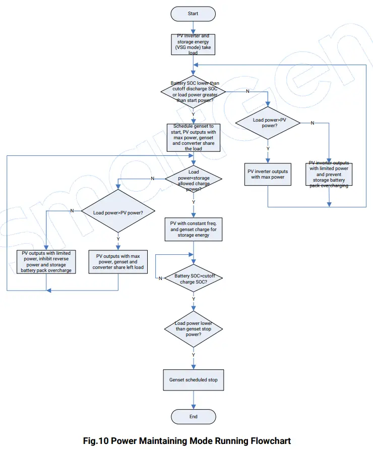
- POWER MAINTAINING MODE
If solar energy and storage energy supply power for load, when storage power is greater than start power of scheduled genset or battery pack SOC is lower than cutoff discharge SOC, genset will start. If PV outputs with max power, storage converter and genset share load, when load power is lower than storage allowed charge power, genset will charge the storage battery pack with constant voltage and frequency of storage rated charge power; otherwise, when load power is greater than PV power, PV outputs with max power, genset and storage share left load. When load power is lower than PV output power, PV output power is limited, genset reverse power is prevented and storage battery pack overcharge is prohibited. When load power is lower than stop power of scheduled genset and battery pack SOC is greater than cutoff charge SOC, genset will stop.
PROTECTIONS
WARNING ALARMS
When controller detects the warning alarm, it only issues warning.
Table 9 Warning Alarms
| No. | Type | Description |
| 1 | PV Comm. Failure | When inverter communication port is enabled and action type selects “Warning”, if controller cannot receive inverter communication data, it will send a warning alarm signal. |
| 2 | Converter Comm. Failure | When converter communication port is enabled and action type selects“Warning”, if controller cannot receive converter communication data, it will send a warning alarm signal. |
| 3 | Genset Comm. Failure | When genset communication port is enabled and action type selects “Warning”, if controller cannot receive genset communication data, it will send a warning alarm signal. |
| 4 | PV Common Warning | When controller receives inverter common warning alarm data, it will send a warning alarm signal. |
| 5 | Converter Common Warning | When controller receives converter common warning alarm data, it will send a warning alarm signal. |
| 6 | Genset Common Warning | When controller receives genset common warning alarm data, it will send a warning alarm signal. |
FAULT ALARMS
When controller detects fault alarms, it will send fault alarm.
Table 10 Fault Alarms
| No. | Type | Description |
| 1 | PV Comm. Failure | When inverter communication port is enabled and action type selects “Fault”, if controller cannot receive inverter communication data, it will send a fault alarm signal. |
| 2 | Converter Comm. Failure | When converter communication port is enabled and action type selects“Fault”,if controller cannot receive converter communication data, it will send a fault alarm signal. |
| 3 | Genset Comm. Failure | When genset communication port is enabled and action type selects “Fault”, if controller cannot receive genset communication data, it will send a fault alarm signal. |
| 4 | PV Common Fault | When controller receives inverter common fault alarm data, it will send a fault alarm signal. |
| 5 | Converter Common Fault | When controller receives converter common fault alarm data, it will send a fault alarm signal. |
| 6 | Genset Common Shut. | When controller receives genset common shutdown alarm data, it will send a fault alarm signal. |
![]() NOTE: When controller receives common alarm common shutdown alarm, common warning alarm, common trip and stop alarm, common trip alarm, common safety trip and stop alarm, common safety trip alarm, common block alarm, corresponding common alarm information will be displayed on current homepage genset information bar.
NOTE: When controller receives common alarm common shutdown alarm, common warning alarm, common trip and stop alarm, common trip alarm, common safety trip and stop alarm, common safety trip alarm, common block alarm, corresponding common alarm information will be displayed on current homepage genset information bar.
WIRING CONNECTION
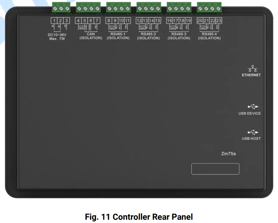
Table 15 Terminal Connection Description
| No. | Function | Size | Remark | |
| 1 | B- | 1.0mm2 | Connect starting battery negative. | |
| 2 | B+ | 1.0mm2 | Connect starting battery positive. | |
| 3 | PE | Protection earth. | ||
| 4 | CAN | Terminal Matching Resistor (120Ω) | 0.5mm2 | Reserved port. 120Ω twisted shielding line is recommended to use with its single end grounded. Short connect terminal 4 and 6, then connect 120Ω terminal resistor. |
| 5 | CAN L | 0.5mm2 | ||
| 6 | CAN H | 0.5mm2 | ||
| 7 | PE1 | Protection earth. | ||
| 8 | RS485-1 | Terminal Matching Resistor (120Ω) | 0.5mm2 | 120Ω twisted shielding line is recommended to use with its single end grounded. Short connect terminal 8 and 10, then connect 120Ω terminal resistor. |
| 9 | B(-) | 0.5mm2 | ||
| 10 | A(+) | 0.5mm2 | ||
| 11 | PE2 | Protection earth. | ||
| 12 | RS485-2 | Terminal Matching Resistor (120Ω) | 0.5mm2 | 120Ω twisted shielding line is recommended to use with its single end grounded. Short connect terminal 12 and 14, then connect 120Ω terminal resistor. |
| 13 | B(-) | 0.5mm2 | ||
| 14 | A(+) | 0.5mm2 | ||
| 15 | PE3 | Protection earth. | ||
| 16 | RS485-3 | Terminal Matching Resistor (120Ω) | 0.5mm2 | 120Ω twisted shielding line is recommended to use with its single end grounded. Short connect terminal 16 and 18, then connect 120Ω terminal resistor. |
| 17 | B(-) | 0.5mm2 | ||
| 18 | A(+) | 0.5mm2 | ||
| 19 | PE4 | Protection earth. | ||
| 20 | RS485-4 | Terminal Matching Resistor (120Ω) | 0.5mm2 | 120Ω twisted shielding line is recommended to use with its single end grounded. Short connect terminal 20 and 22, then connect 120Ω terminal resistor. |
| 21 | B(-) | 0.5mm2 | ||
| 22 | A(+) | 0.5mm2 | ||
| 23 | PE5 | Protection earth. | ||
![]() NOTE1: Slave USB port on the controller side is used for upgrading controller firmware.
NOTE1: Slave USB port on the controller side is used for upgrading controller firmware.![]() NOTE2: Master USB port on the controller side is used for updatingcontroller display pictures and word stock.
NOTE2: Master USB port on the controller side is used for updatingcontroller display pictures and word stock.![]() NOTE3: ETHERNET port on the controller side is reserved port.
NOTE3: ETHERNET port on the controller side is reserved port.
7 SCOPES AND DEFINITIONS OF PROGRAMMABLE PARAMETERS
Table 12 Parameter Contents and Scopes
| No. | Item | Range | Default | Description | |
| Timer Setting | |||||
| 1 | Start Delay | (0-3600)s | 1 | Time from storage battery SOC is lower than cutoff discharge SOC or load power is greater than scheduled start percentage to genset start. | |
| 2 | Stop Delay | (0-3600)s | 1 | Time from storage battery SOC is greater than cutoff charge SOC or load power is lower than scheduled stop percentage to genset stop. | |
| Module Setting | |||||
| 1 | Module Address | (1-254) | 1 | ||
| 2 | Language | (0-1) | 0 | 0: Simplified Chinese; 1: English | |
| 3 | Password | (0-65535) | 00318 | ||
| 4 | RS485 -1 | Baud Rate | (0-2) | 1 | 0: 4800bps; 1: 9600bps; 2: 19200bps |
| 5 | Parity | (0-2) | 0 | 0: None; 1: Odd Parity; 2: Even Parity | |
| 6 | Stop Bit | (0-1) | 0 | 0: 2bit; 1: 1bit | |
| 7 | RS485 -2 | Baud Rate | (0-2) | 1 | 0: 4800bps; 1: 9600bps; 2: 19200bps |
| 8 | Parity | (0-2) | 0 | 0: None; 1: Odd Parity; 2: Even Parity | |
| 9 | Stop Bit | (0-1) | 0 | 0: 2bit; 1: 1bit | |
| 10 | RS485 -3 | Baud Rate | (0-2) | 1 | 0: 4800bps; 1: 9600bps; 2: 19200bps |
| 11 | Parity | (0-2) | 0 | 0: None; 1: Odd Parity; 2: Even Parity | |
| 12 | Stop Bit | (0-1) | 0 | 0: 2bit; 1: 1bit | |
| 13 | RS485 -4 | Baud Rate | (0-2) | 1 | 0: 4800bps; 1: 9600bps; 2: 19200bps |
| 14 | Parity | (0-2) | 0 | 0: None; 1: Odd Parity; 2: Even Parity | |
| 15 | Stop Bit | (0-1) | 0 | 0: 2bit; 1: 1bit | |
| System Setting | |||||
| System Application | |||||
| 1 | Application Mode | (0-1) | 0 | 0: Economy Mode; 1: Power Maintaining Mode. | |
| Converter Setting | |||||
| 1 | Rated Active Power | (0-6000)kW | 500 | PCS rated active power. | |
| 2 | Rated Reactive Power | (0-6000)kvar | 500 | PCS rated reactive power. | |
| 3 | Converter Model | (0-49) | 0 | 0: SC50HV | |
| 4 | Communication ID | (1-254) | 1 | Converter communication address. | |
| 5 | Comm. Failure Delay | (0-3600)s | 5 | Delay time from the module cannot receive monitoring data to controller issues communication failure alarm during communication. | |
| 6 | Comm. Failure Action | (0-2) | 1 | 0: None; 1: Warning; 2: Fault alarm. | |
| 7 | Communication Port | (0-4) | 0 | 0: Not used 1: RS485(1) 2: RS485(2) 3: RS485(3) 4: RS485(4) | |
| 8 | Storage Charge Power | (0-100)% | 50 | Storage battery charge power. | |
| 9 | Cutoff Discharge SOC | (0-100)% | 30 | When storage battery SOC is lower than cutoff discharge SOC, genset will start. | |
| 10 | Cutoff Charge SOC | (0-100)% | 100 | When storage battery SOC is greater than cutoff charge SOC, storage battery pack charge is over. | |
| Inverter Setting | |||||
| 1 | Rated Active Power | (0-6000)kW | 500 | Rated active power of inverter. | |
| 2 | Rated Reactive Power | (0-6000)kvar | 500 | Rated reactive power of inverter. | |
| 3 | Inverter Model | (0-50) | 0 | 0: First Running. | |
| 4 | Inverter ID | (1-254) | 2 | Inverter communication address. | |
| 5 | Comm. Failure Delay | (0-3600)s | 5 | Delay time from the module cannot receive monitoring data to controller issues communication failure alarm during communication. | |
| 6 | Comm. Failure Action | (0-2) | 1 | 0: None; 1: Warning; 2: Fault alarm. | |
| 7 | Communication Port | (0-4) | 0 | 0: Not used 1: RS485(1) 2: RS485(2) 3: RS485(3) 4: RS485(4) | |
| 8 | DC Channel | (1-4) | 2 | DC input channel of PV inverter. | |
| Genset Setting | |||||
| 1 | Rated Active Power | (0-6000)kW | 500 | Rated active power of genset. | |
| 2 | Rated Reactive Power | (0-6000)kvar | 500 | Rated reactive power of genset. | |
| 3 | Genset ID | (1-254) | 3 | Genset communication address. | |
| 4 | Comm. Failure Delay | (0-3600)s | 5 | Delay time from the module cannot receive monitoring data to controller issues communication failure alarm during communication. | |
| 5 | Comm. Failure Action | (0-2) | 1 | 0: None; 1: Warning; 2: Fault alarm. | |
| 6 | Communication Port | (0-4) | 0 | 0: Not used 1: RS485(1) 2: RS485(2) 3: RS485(3) 4:RS485(4) | |
| 7 | Scheduled Stop Power | (0-100)% | 30 | When storage capacity is greater than cutoff charge SOC and load power is lower than this value, schedule genset to stop. | |
| 8 | Scheduled Start Power | (0-100)% | 80 | When storage load power is greater than this value, schedule genset to start. | |
| 9 | Freq. Center Point | (10.0-75.0) Hz | 50.0 | Droop frequency center point of genset active power. | |
| 10 | Active Droop | (0-200.0)% | 2.0 | Genset active droop percentage. | |
| 11 | Volt Center Point | (30-30000)V | 230 | Droop frequency center point of genset reactive power. | |
| 12 | Reactive Droop | (0-200.0)% | 2.0 | Genset reactive droop percentage. | |
| 13 | Min. Load Power | (0-100)% | 10 | Genset allowed min. load power. | |
| 14 | Allowed Storage Charge Power | (0-100)% | 80 | When load power is lower than allowed storage charge power, it will charge for battery pack. | |
| Energy Saving and Emission Reduction Setting | |||||
| 1 | Equivalent Tree Plant Factor | (0-9.9999) | 5.023 g/day | The average daily amount of CO2 absorbed by an ordinary tree. | |
| 2 | Reduce C02 Factor | (0-9.9999) | 0.785 kWh/kg | CO2 emission reduction amount for every 1kWh generated by PV. | |
| 3 | Save Standard Coal Factor | (0-9.9999) | 0.123 kg | The standard coal amount required for every 1kWh power. | |
| 4 | Equivalent Economic Factor | (0-9.9999) | 0.700 yuan/kWh | Price of 1kWh power. | |
SYSTEM STRUCTURE TOPOLOGY
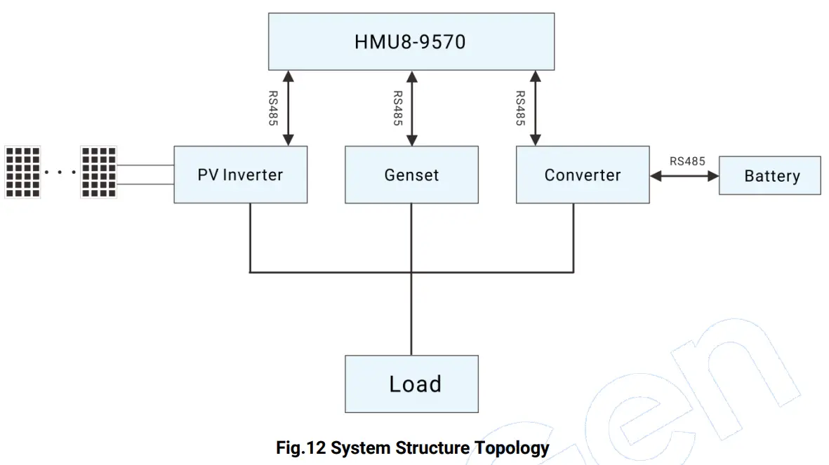
HMU8-9570 can perform data monitoring and communication with PV inverter, genset and converter via RS485 port. BMS and PCS can make data communication via RS485.
RUNNING EXAMPLE
Table 13 System Running Example
| Status | Diagram |
| When load power is lower than genset scheduled start power and storage battery pack SOC is greater than cutoff discharge SOC, solar energy and storage energy will supply power for load. | 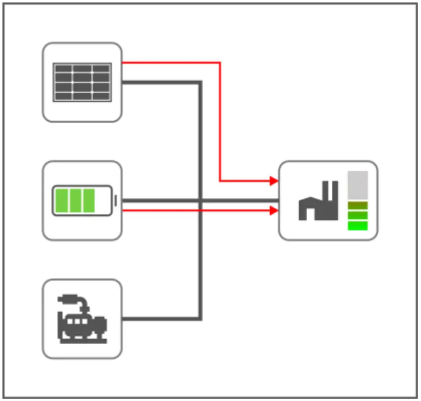 |
| When load power is greater than genset scheduled start power, genset will start, solar energy, storage battery and genset will supply power for load. | 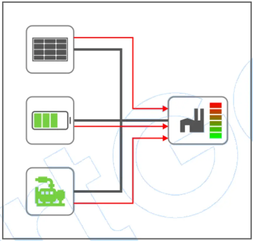 |
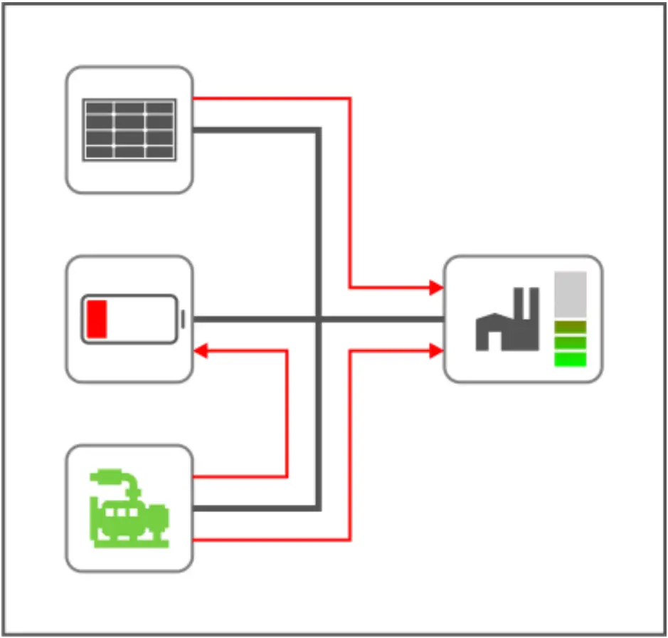
| When load power is lower than scheduled start power, storage battery SOC is lower than cutoff discharge SOC, solar energy and genset supply power for load. In economy mode, genset will not charge for storage battery. In power maintaining mode, genset will charge for storage battery. | 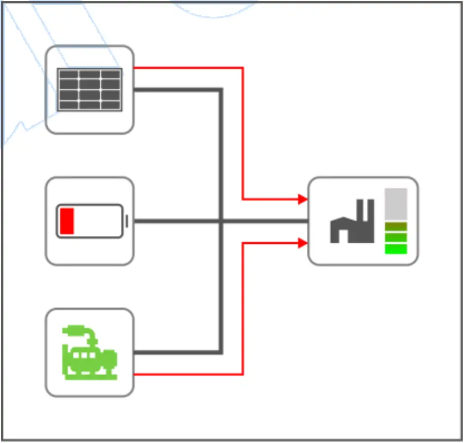 Economy Mode
|
| When load power is lower than scheduled stop power, storage battery SOC is greater than cutoff discharge SOC, genset will stop, solar energy will supply power for load and charge for storage battery. | 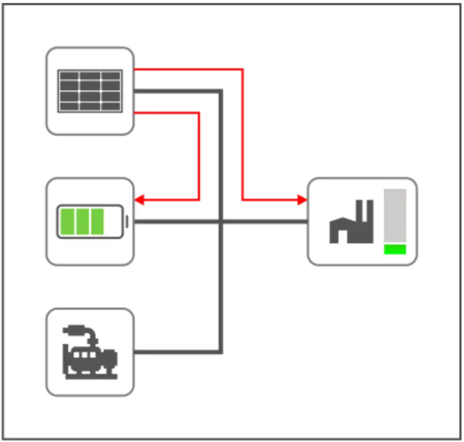 |
| When load power is lower than scheduled stop power, storage battery SOC is greater than cutoff charge SOC, genset will stop, solar energy will supply power for load. When solar energy power is too large, its power needs to be limited. | 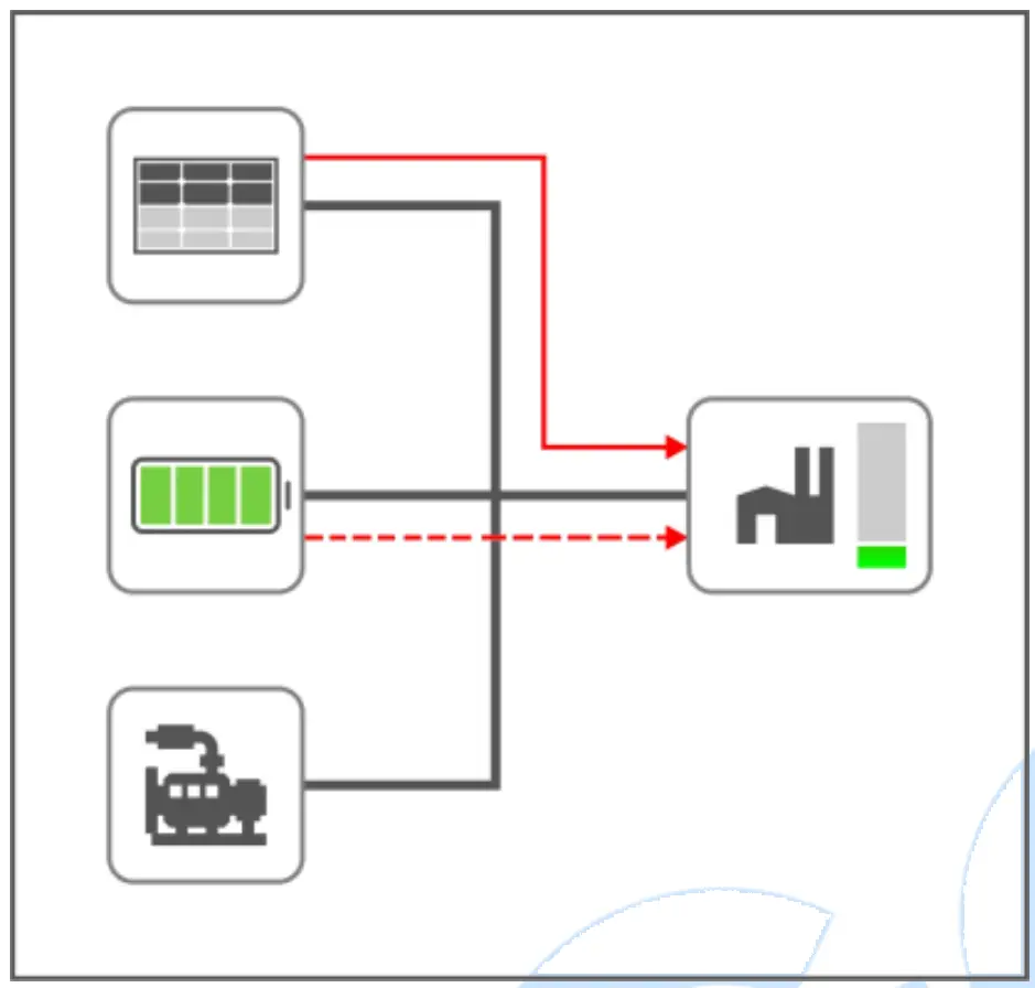 |
COMMISSIONIN
Before formal running, please make the following checking:
- Check whether all connection wires are correct and diameter is suitable;
- Check whether DC power has fuse, connect it to power’s positive and negative, turn on the supply switch;
- Check whether battery pack and storage converter is correctly connected, then turn on the master switch of battery pack, press “Start” key;
- Turn on the DC input switch and AC output switch of storage converter, set converter as VSG mode, start the converter through converter operation software and wait for normal running;
- Turn off the PV inverter and grid switch, turn on the inverter DC switch and wait PV inverter enter normal running;
- Set HES9570 genset controller in auto mode;
- View whether each monitoring parameter of controller is normal;
- View system running conditions with load;
- If there is any question, please contact our service personnel in time
INSTALLATION
FIXING CLIPS
─ This controller is panel-mounted and fixed by clips;
─ Withdraw the fixing clip screw (turn anticlockwise) until it reaches proper position;
─ Pull the fixing clip backwards (towards the back of the module) and ensure four clips are inside their allotted slots;
─ Turn the fixing clip screws clockwise until they are fixed on the panel;
─ Care should be taken not to over tighten the screws of fixing clips, torque is 2.75kgf.cm (0.27N.m).
CASE DIMENSION AND PANEL CUTOUT
FAULT FINDING
Table 14 Fault Finding
| Symptoms | Possible Solutions |
| Controller no response for power | Check starting voltage; Check controller connection wires; Check DC fuse. |
| PV inverter comm. abnormal Converter comm. abnormal Genset comm. abnormal | Check connection wires; Check settings of COM port is correct or not; Check RS485’s A and B connections is reversely connected or not; Check 120Ω terminal resistor of communication line is matched or not. |