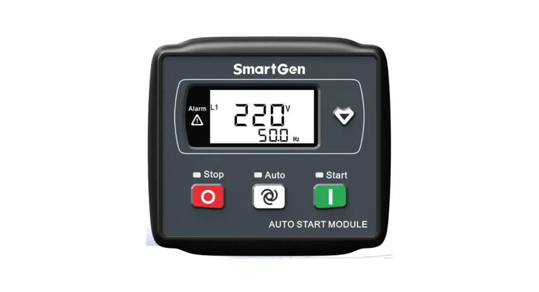
![]() HGM1790N
HGM1790N
GENSET CONTROLLER
USER MANUAL
SMARTEN(ZHENGZHOU)TECHNOLOGY CO., LTD.
All rights reserved. No part of this publication may be reproduced in any material form (including photocopying or storing in any medium by electronic means or other) without the written permission of the copyright holder.
Applications for the copyright holder’s written permission to reproduce any part of this publication should be addressed to Smartgen Technology at the address above.
Any reference to trademarked product names used within this publication is owned by their respective companies.
SmartGen Technology reserves the right to change the contents of this document without prior notice.
Table 1 Software Version
| Date | Version | Note |
| 2016-10-11 | 1.0 | Original release. |
| 2017-10-09 | 1.1 | 1) Changed “Stop Output Relay” and “Idle Control Relay” into “Aux. Output”; Changed rare panel description and typical application description; Added “Aux. Output 1” and “Aux. Output 2” configuration options. 2) Modified storage temperature. |
| 2020-09-30 | 1.2 | Modified the incorrect word spell “Frequency” of 4.4 “ LCD ICONS”. |
| 2021-03-18 | 1.3 | Modified the error in table 7 and other translation problems. |
| 2021-09-30 | 1.4 | Added Outputs Contents “7: Rated Speed Output 8: Over Speed Output” in Table 8. |
| 2022-06-10 | 1.5 | Updated the logo of SmartGen. |
OVERVIEW
HGM1790N Genset controller is suited for single unit automation and monitoring control (also can be used for pumping unit). It can realize manual start/stop of the genset, and it can also automatically start/stop Genset by remote start signal. HGM1790N controller can supervise and protect Genset operation by gathering and analyzing Genset data like generated voltage, current, water temperature, oil pressure, and so on, and it can indicate fault conditions and do maintenance as soon as possible. The graphical LCD and touch-button operation make it clear and intuitive. Moreover, parameter threshold and delay value can be adjusted via front panel or USB port (communicated with PC software).
PERFORMANCE AND CHARACTERISTICS
- Graphical LCD display (with backlight), LED indicator, touch-buttons operation;
- Hard screen acrylic material is used to protect the screen.
- Silicone panel and buttons are adopted to increase high and low-temperature adaption ability;
- Power supply range DC (8~35)V, compatible with 12V or 24V starting batteries;
- Generator single phase voltage, current, frequency, power, and load percentage parameters are measured and displayed:
Generator Voltage V
Generator Power kW
Load Percentage %Generator Frequency Hz
Generator Current A - Precision-measured and displayed parameters of engine:
Oil Pressure kPa
Fuel Level %
Battery Voltage VTemperature ºC
Total Running Time H (max. 199999 hours)
Engine Speed RPMAccumulated Start Times (max. 199999 times, displayed on PC)
- With genset fault protection and display functions.
- 3 working modes: manual, auto, stop;
- Compatible with multiple temperatures, pressure, and fuel level sensors, which can be user-defined and used directly; temperature sensors and pressure sensors can be used in parallel with an annunciator, providing analog quantity and increasing protection level at the same time;
- Multiple crank disconnect conditions to select (engine speed sensor, oil pressure, generator frequency);
- 1 configurable input port which can be set as digital input or liquid level sensor;
- 2 fixed relay outputs (fuel relay, start relay);
- 3 configurable output ports which can be set as a common alarm output, preheat output, or idle control output;
- Parameters can be set and modified by users and saved in internal FLASH storage, which means that they will not be lost in case of power off. Most parameters of the controller can be modified using the front panel and all parameters can be adjusted by PC software via a type-B USB port;
- Digital regulation of all parameters – instead of analog regulation using a conventional potentiometer, therefore, higher reliability and stability;
- Modular design, self-extinguishing ABS plastic enclosure, and embedded installation way; small size and compact structure with easy mounting
SPECIFICATION
Table 2 Technical Parameters
| Item | Content |
| Working Voltage | DC8. 0V to 35. 0V, Continuous Power Supply |
| Power Consumption | <1.2W (Standby mode: ≤0.5W) |
| Alternator Voltage Input | AC 15V ~ AC 360 V (ph-N) |
| Alternator Frequency | 50Hz/60Hz |
| Speed Sensor Voltage | 1.0V to 24V (RMS) |
| Speed Sensor Frequency | Max. 10, 000Hz |
| Start Relay Output | 1Amp DC28V DC B+ power supply |
| Fuel Relay Output | 1Amp DC28V DC B+ power supply |
| Aux. Output1 | 1Amp DC28V DC B+ power supply |
| Aux. Output2 | 1Amp DC28V DC B+ power supply |
| Aux. Output3 | 1Amp DC28V DC B+ power supply |
| Programmable Digital Input | Active when connected to B- |
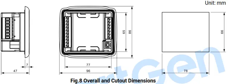
| Case Dimensions | 95mm x 86mm x 46.5mm |
| Panel Cutout | 78mm x 66mm |
| CT Secondary Current | Rated: 5A |
| Working Temperature | (-25~+70)ºC |
| Working Humidity | (20~93)%RH |
| Storage Temperature | (-25~+70)ºC |
| Protection Level | IP55: When a waterproof rubber gasket is installed between the controller and panel fascia. |
| Insulation Intensity | Attach AC2.2kV voltage between AC high voltage terminal and low voltage terminal (leak current below 3mA in 1 minute). |
| Weight | 0.18kg |
OPERATION
4.1. FRONT PANEL DESCRIPTION
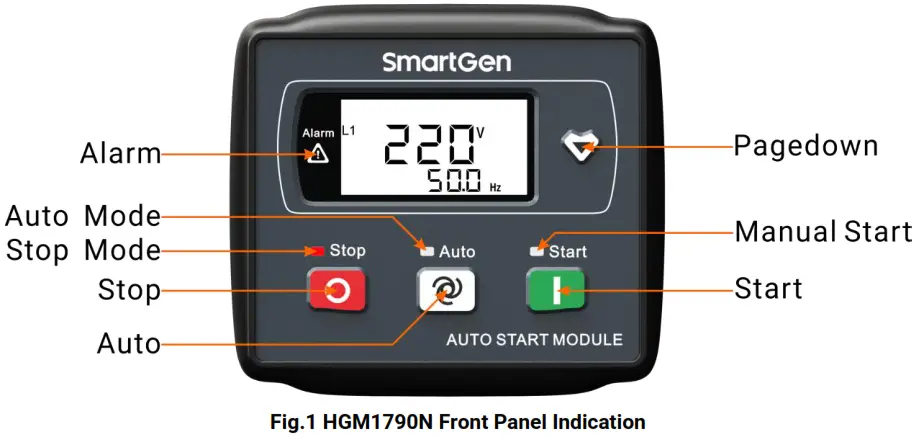
4.2. INDICATOR DESCRIPTION
Stop status indicator light: Genset in stop mode.
Auto status indicator light: Genset in auto mode.
Manual start indicator light: Genset in manual mode.
Alarm indicator light: blink slowly (1 time/s) when warn alarm occurred; blink fast (5 times/s) when the shutdown alarm occurred.
4.3. PANEL KEYS
Table 3 Key Descriptions
| Key | Definition | Description |
| Stop/Reset | In auto/manual mode, pressing this button will shutdown the Genset; Reset shutdown alarms when Genset is in alarm status; Indicator lights and LCD icons status can be tested when pressing this button for over 3s in stop mode; Stop immediately if press this button during stop process; Quick exist parameter setting menu if the press this button. | |
 | Auto/Increase | Pressing this button will place the module into its auto mode, and Genset is controlled by remote start signals; In the settings menu moves the cursor up and increase the set value. |
 | Start/Decrease | Pressing this button will start Genset. In settings menu moves the cursor down and decreases the set value. |
 | Page Down | Using this button you can scroll pages of the LCD monitor; Enter the settings menu if hold and press over 2s; Move the cursor and confirm setting information in the parameter setting menu. |
4.4. LCD ICONS
| Icon | Definition | Icon | Definition |
 | Genset Start Indication | FL | Fuel Level Indication |
 | Boot time is counting (reaching crank disconnect condition) | L1 | Generator Voltage Indication |
 | Emergency Stop Alarm | DC | Battery Voltage Indication |
 | Over Speed/Over Frequency Alarm | hPa | Oil Pressure Unit |
 | Under Speed/Under Frequency Alarm | A | Current With Load Unit |
| High Temp. Alarm | H | Hours Count | |
| Low Fuel Level | Hz | Frequency Unit | |
| Auxiliary Alarm | °C | Temperature Unit | |
| Low Oil Pressure | rpm | Speed Unit (revolutions per minute) | |
| Fail to Start | kW | Active Power Unit | |
| Fail to Stop | V | Voltage Unit | |
| Voltage Abnormal | % | Percentage | |
 | Over Voltage | ||
 | Under Voltage | ||
| Over Current With Load |
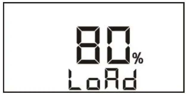
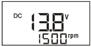
4.5. DISPLAY DESCRIPTION
| Generator: phase voltage L1, frequency F | Load percentage |
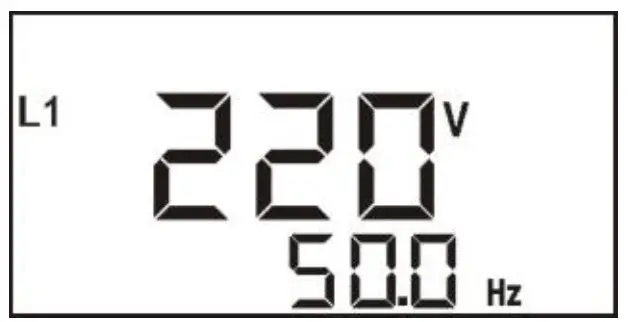 |  |
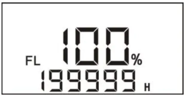
| Fuel level, total running time | Parameter setting |
 |  |
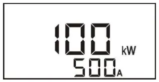
| Load: active power, current | Oil pressure, temperature |
 | 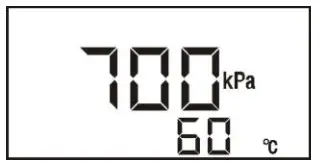 |
Battery voltage, engine speed
 NOTE:
NOTE:
- When active power is “—”, which means active power is negative, please check voltage and current connection.
- When pressure, temperature, and liquid level sensors are not displayed, which means not used; when displayed “OFF” means sensors are open circuit.
- When total running time is lower than 20000 hours, the value before the decimal point means running hours, and the value after the decimal point means 1/10 hour.
4.6. AUTO START/STOP OPERATION
Auto mode is selected by pressing![]() ; a LED beside the button will illuminate to confirm the operation.
; a LED beside the button will illuminate to confirm the operation.
Automatic Start Sequence:
- When “Remote Start” is active (6 terminals connected with B-), the “Start Delay” timer is initiated;
- When the start delay is over, preheat relay energizes (if configured), and the “Preheat Delay” starts to count.
- After the preheat delay, the Fuel Relay (if configured) is energized, and then one second later, the Start Relay is engaged. If the genset fails to fire during “Cranking Time”, then the fuel relay and start relay stop to output; “Crank Rest Time” begins and wait for the next crank attempt.
- Should this start sequence continue beyond the set number of attempts, the start sequence will be terminated
 and will be displayed on the LCD meaning Fail to Start, and meanwhile, the alarm indicator light is blinking.
 - In case of a successful crank attempt, the “Safety On” timer is activated, and Low Oil Pressure, High Temperature, and other alarms are inactive during the period. As soon as this delay is over, the “Start Idle” delay is initiated (if configured).
- During the “Start Idle” delay, under-speed, under-frequency, and under-voltage alarms are inhibited. When this delay is over, a “Warming up” delay is initiated (if configured).
- When the “Warming up” delay is over, Genset starts normal running; if the generator voltage or frequency is abnormal, shutdown alarm signals will be sent by the controller.
Automatic Stop Sequence,
- When the “Remote Start” signal is removed, “Stop Delay” is initiated.
- Once this “Stop Delay” has expired, the “Cooling Delay” is then initiated.
- During the “Stop Idle” Delay (if configured), the idle relay is energized.
- ETS Solenoid Hold” begins, the ETS relay is energized while the fuel relay is de-energized.
- Fail to Stop Delay” begins, and the complete stop is detected automatically.
- The generator is placed into its standby mode after its “After stop” delay. Otherwise, fail to stop alarm is initiated. (LCD display
 )
)
![]() NOTE:
NOTE:
a) When pressing the stop button in auto start status, the Genset will stop and enter into stop mode simultaneously.
b) In process of crank rest delay, preheat and ETS functions are energized when fuel output is de-energized and crank rest time countdown is less than 7s. After the crank rest delay, the ETS output is de-energized, the fuel relay starts output, and preheat relay output is off before the crank.
4.7. MANUAL START/STOP OPERATION
- MANUAL START: Press
 the button to start the Genset (No.2~7 of Automatic Start Sequence for detail procedures). With high temperature, low oil pressure, over speed, and abnormal voltage during generator running, the controller can protect Genset to stop quickly.
 - MANUAL STOP: Press
 can shut down the running Genset. (Please refer to No.2~6 of Automatic Stop Sequence for detailed procedures).
PROTECTION
Table 5 Controller Alarms
| Icons | Alarms | Type | Triggering Condition |
| Emergency Shut Alarm | Shut Alarm | The controller sent alarms when detected emergency shutdown alarms. |
| Over Speed Shut | Shut Alarm | Controller sent alarms when Genset speed is higher than over speed threshold and lasts for over 2s. |
| Over Frequency Shut | Shut Alarm | Controller sent alarms when generator frequency is higher than over frequency threshold and lasts for over 2s. | |
| Under Speed Shut | Shut Alarm | Detection after warming up delay, controller sent alarms when speed is lower than under speed threshold and lasts for over 10s. |
| Under Frequency Shut | Shut Alarm | Detection when Genset is normal running, controller sent alarms once Genset frequency fell below under frequency threshold and lasts for over 10s. | |
|
| High Temp. Shut | Shut Alarm | Detection after safe running delay, controller sent alarms once Genset temperature is higher than over temp. threshold and lasts for over 3s. |
| High Temp. Input Shut | Shut Alarm | Detection after safe running delay, controller sent alarms when high-temperature input is active. | |
| Temp. Sensor Open/Short Circuit Shut | Shut Alarm | Detection after safe running delay, controller sent alarms when the temperature sensor resistance value is above 6000Ω or under 5Ω. | |
 | Low Oil Pressure Shut | Shut Alarm | Detection after safe running delay, controller sent alarms when Genset oil temperature is lower than low oil pressure threshold and lasts for over 2s. |
| Low Oil Pressure Input Shut | Shut Alarm | Detection after safe running delay, controller sent alarms when low oil pressure input is active. | |
| Oil Pressure Sensor Open/Short Circuit Shut | Shut Alarm | Detection after safe running delay, controller sent alarms when oil pressure sensor resistance value is above 6000Ω or under 5Ω. |

| Icons | Alarms | Type | Triggering Condition |
| Gen Over Current Warn | Warn Alarm | Controller sent alarms when generator current is higher than the preset value and over current action is selected as “Warn”. | |
| Gen Over Current Shut | Shut Alarm | Controller sent alarms when generator current is higher than the preset value and lasts for over the delay value (over current action is selected as “Shutdown”). | |
| Gen Over Current Cooling Shut | Shut Alarm | Controller sent alarms when generator current is higher than the preset value and lasts for over than delay value (over current action is selected as “Cooling Shutdown”). | |
| Gen Over Volt Shut | Shut Alarm | Detection after safe running delay, controller sent alarms when generator voltage is higher than over than voltage threshold and lasts for over than voltage abnormal delay value. | |
| Gen Low Volt Shut | Shut Alarm | Detection after safe running delay, controller sent alarms when generator voltage is lower than under voltage threshold and lasts for over than voltage abnormal delay value. |
 | Fail to Start | Shut Alarm | Controller Sent alarms when Genset fails to start in preset attempts. |
| Auxiliary Shut Alarm Input | Shut Alarm | The controller sent alarms when the auxiliary input port, which is configured as an “auxiliary shutdown alarm input”, is active. | |
| Low Fuel Level Warn | Warn Alarm | Controller sent alarms when fuel level is lower than low fuel level threshold and lasts for over 10s. | |
| Low Fuel Level Input Warn | Warn Alarm | The controller sent alarms when low fuel level input is active. | |
| Fuel Level Sensor Open/Short Circuit Warn | Warn Alarm | Controller sent alarms when Fuel level sensor resistance value is above 6000Ω or under 5Ω. | |
| Fail to Stop | Warn Alarm | The controller sent alarms when Genset fail to stop in stop duration. | |
| Low Battery Volt Warn | Warn Alarm | Controller sent alarms when battery voltage is lower than under voltage threshold and lasts for over 20s. | |
| High Battery Volt Warn | Warn Alarm | The controller sent alarms when the battery voltage is higher than the over-voltage threshold and lasts for over 20s. |
WIRING CONNECTION
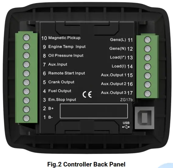
Table 6 Terminals Description
| No. | Function | Cable Size | Remarks |
| 1 | DC Voltage Input B- | 1.5mm2 | Connect to negative of starting battery |
| 2 | DC Voltage Input B+ | 1.5mm2 | Connected to positive of starting battery. If the wire length is over 30m, better to double wires in parallel. Max. 20A fuse is recommended. |
| 3 | Emergency Stop Input | 1.0mm2 | B+ voltage input is active and connected to the emergency stop normally closed button. |
| 4 | Fuel Output | 1.0mm2 | B+ is supplied by No.3 point, rated 1A. |
| 5 | Crank Output | 1.0mm2 | B+ is supplied by No.3 point, rated 1A. |
| 6 | Remote Start Input | 1.0mm2 | Ground connected is active (B-) |
| 7 | Aux. Input | 1.0mm2 | Ground connected is active (B-) if it is configured as a digital input. Connect to low fuel level coil or fuel level resistor type sensor if it is configured as a level sensor. |
| 8 | Oil Pressure Input | 1.0mm2 | Connect to low oil pressure coil or resistor type sensor. |
| 9 | Engine Temp. Input | 1.0mm2 | Connect to high water/cylinder temp. coil or temperature resistor type sensor. |
| 10 | Magnetic Pickup | 0.5mm2 | Connect to speed sensor, and shielded wire is recommended. The other end of the speed sensor is connected to B-. |
| 11 | Gen Volt Monitoring | 1.0mm2 | Connect to generator voltage output port. (2A fuse is |
| No. | Function | Cable Size | Remarks |
| 12 | Input | 1.0mm2 | recommended) |
| 13 | Load Current (Inlet Loop) | 1.5 mm2 | Connect to the secondary coil of the current transformer. (Rated 5A) |
| 14 | Load Current (Outlet Loop) | 1.5 mm2 | |
| 15 | Aux. Output 1 | 1.0 mm2 | B+ is supplied by No.2 point, rated 1A. |
| 16 | Aux. Output 2 | 1.0 mm2 | B+ is supplied by No.2 point, rated 1A. |
| 17 | Aux. Output 3 | 1.0 mm2 | B+ is supplied by No.2 point, rated 1A. |
![]() NOTE: Type-B USB port, which can be connected with PC software, is applied for parameter configuration and data monitoring.
NOTE: Type-B USB port, which can be connected with PC software, is applied for parameter configuration and data monitoring.
PARAMETER RANGE AND DEFINITION
7.1 PARAMETERS CONTENTS AND RANGE
Table 7 Parameter Setting Contents and Range
| No. | Parameter | Range | Default Value | Description |
| P00 | Start Delay | (0-3600)s | 1 | Time from remote start signal is active to start Genset. |
| P01 | Stop Delay | (0-3600)s | 1 | Time from remote start signal is deactivated to stop Genset. |
| P02 | Start Attempts | (1-10) times | 3 | The maximum number of crank attempts. If none of them is successful, the controller will initially fail to start the alarm. |
| P03 | Preheat Time | (0-300)s | 0 | Time of pre-powering heat plug before the starter is powered up. |
| P04 | Cranking Time | (3-60)s | 8 | The time of powering up the starter for every crank attempt |
| P05 | Crank Rest Time | (3-60)s | 10 | The waiting time before the second power-up when the engine starts to fail. |
| P06 | Safety On Delay | (1-60)s | 10 | Alarms for low oil pressure, high temperature, under-speed, under frequency, and under voltage are inactive. |
| P07 | Start Idle Time | (0-3600)s | 0 | Idle running time of Genset when starting. |
| P08 | Warming Up Time | (0-3600)s | 10 | Warming time between Genset switch on and normal running. |
| P09 | Cooling Time | (3-3600)s | 10 | Radiating time before Genset stop, after it unloads. |
| P10 | Stop Idle Time | (0-3600)s | 0 | The idle running time when Genset stops. |
| P11 | ETS Solenoid Hold | (0-120)s | 20 | The time of powering up the electromagnet during the stop procedure. |
| P12 | Fail to Stop Delay | (0-120)s | 0 | The time between the ending of Genset idle delay and stopped when “ETS output time” is set as 0; The time between the ending of the ETS hold is delayed and stopped when the “ETS output time” is not 0. |
| P13 | Flywheel Teeth | (1-300) | 118 | The tooth number of the engine is for judging crank disconnect conditions and inspecting engine speed. See the installation instructions. |
| No. | Parameter | Range | Default Value | Description |
| P14 | Generator Poles | (2-16) | 4 | Configuring numbers of generator poles. |
| P15 | Generator Abnormal Time | (0-20.0)s | 10.0 | Alarm delay for generator over and under voltage states. |
| P16 | Generator Over Voltage | (30-1000)V | 264 | When the generator voltage exceeds this value and stays so for the time of “Generator Abnormal Time”, it is regarded as over-voltage and Generator Over Voltage shutdown alarm is initiated. If the voltage value is 1000V, the over-voltage signal is not initiated. |
| P17 | Generator Under Voltage | (30-1000)V | 196 | When the detected voltage falls below this value and stays so for the time of “Generator Abnormal Time”, it is regarded as under voltage and Generator Under Voltage shutdown alarm is initiated. If the voltage value is 30V, under voltage signal is not initiated. |
| P18 | Engine Under Speed | (0-6000)RPM | 1200 | When engine speed falls below this value and stays so for 10s, this is regarded as under speed and under speed alarm shutdown signal is sent. |
| P19 | Engine Over Speed | (0-6000)RPM | 1710 | When engine speed exceeds this value and stays so for 2s, this is regarded as over speed and over speed alarm shutdown signal is sent. |
| P20 | Under Frequency | (0-75.0)Hz | 45.0 | When generator frequency falls below this value and not 0, and stays so for 10s, it is regarded as under frequency, and under frequency alarm shutdown is initiated. |
| P21 | Over Frequency | (0-75.0)Hz | 57.0 | When generator frequency exceeds this value and stays so for 2s, it is regarded as an over frequency, and over frequency, alarm shutdown is initiated. |
| P22 | High Temperature | (80-140)ºC | 98 | When the temperature value of the external temperature sensor exceeds this threshold, the high-temperature signal is sent. Detection starts after safety |
| No. | Parameter | Range | Default Value | Description |
| delay and only concerns the external temperature sensor which is connected to the temperature sensor input port. If the set value is 140, the high-temperature signal will not be sent (this only concerns the temperature sensor, not the high-temperature signal via config. input port). | ||||
| P23 | Low Oil Pressure | (0-40)kPa | 103 | When the external pressure sensor value falls below this threshold, low oil pressure delay begins. Detection begins after safely on delay. If the set value is 0, the low oil pressure signal is not sent (this only concerns the pressure sensor and does not concern low oil pressure warning signal via configurable input port) |
| P24 | Low Liquid Level | (0-100)% | 10 | When the liquid level of the external sensor falls below this value and stays so for 10s, the low liquid level signal is sent and a warning without shutdown is initiated. |
| P25 | Battery Over Volts | (12-40)V | 33.0 | When the battery voltage exceeds this value and stays so for the 20s, Battery Over Volts signal is sent and a warning without the shutdown is initiated. |
| P26 | Battery Under Volts | (4-30)V | 8.0 | When battery voltage falls below this value and stays so for the 20s, Battery Under Volts signal is sent and warning without shutdown is initiated. |
| P27 | CT Ratio | (5-6000)/5 | 500 | Current transformer ratio defaults as 500:5. |
| P28 | Full-load Current | (5-1900)A | 500 | It is the rated current of the generator, which is applied for calculating the over current with the load. |
| P29 | Over Current Percentage | (50-130) | 120 | The over-current delay starts when the current with load is greater than the value of full-load current multiplied over the current percentage. |
| P30 | Over Current | (0-3600)s | 60 | When the current with load exceeds preset |
| No. | Parameter | Range | Default Value | Description |
| Delay | value and stays so over delay time, over-current alarm will be initiated. | |||
| P31 | Action | (0-2) | 0 | 0: Warn 1: Shutdown 2: Cooling and Shutdown |
| P32 | Aux. Output 3 | (0-9) | 1 | Default: Common Alarm |
| P33 | Digital Input | (0-8) | 4 | Default: Auxiliary shutdown; if the set value is 8, fuel level sensor type can be selected. |
| P34 | Digital Input Delay | (0-20.0)s | 2.0 | Active delay time for digital input ports |
| P35 | Power On Mode | (0-2) | 0 | 0: Stop 1: Manual 2: Auto |
| P36 | Password Set | (0-9999) | 0318 | |
| P37 | Crank Disconnect Condition | (0-6) | 1 | See table 11. Starter disconnection condition. There are 3 conditions of disconnecting the ing starter the ith engine (speed, generator frequent,ency and oil pressure). Aiming at to separate the start motor and engine as soon as possible. |
| P38 | Disconnect Engine Speed | (0-3000) RPM | 360 | When speed is higher than the set value ue, the starter will be disconnected. |
| P39 | Disconnect Generator Freq | (10.0-30.0) Hz | 14.0 | When hen generator frequencies ncy higher than the set value, the starter will be disconnected. |
| P40 | Disconnect Oil Pressure | (0-400) kPa | 200 | When generator oil pressure is higher than the set value, the starter will be disconnected and the oil engine crank successfully. |
| P41 | AC System | (0-3) | 2 | 0: 3P4W 1: 2P3W 2: 1P2W 3: 3P3W It is used for calculating generator voltage and active power. |
| P42 | Temp. Sensor | (0-10) | 06 | SGD (120ºC resistor type) |
| P43 | OP Sensor | (0-10) | 06 | SGD (10Bar resistor type) |
| P44 | Fuel Level Sensor | (0-7) | 0 | Not used. (If the fuel level sensor is used, then the digital input port must be set as “8 Multiplex Level Sensor”. |
| P45 | Disconnect Oil Pressure Delay | (0-20.0)s | 0.0s | When crank disconnect conditions including oil pressure, engine oil pressure, and delay value are higher |
| No. | Parameter | Range | Default Value | Description |
| than set values, starter will be disconnected and the oil engine crank successfully. | ||||
| P46 | Aux. Output 1 | (0-9) | 3 | Default: Idle Speed Output |
| P47 | Aux. Output 2 | (0-9) | 2 | Default: ETS Output |
7.2 DEFINABLE CONTENTS OF RELAY OUTPUTS
Table 8 Definable Contents of Relay Outputs
| No. | Items | Description | |
| 0 | Not Used | Output is not active. | |
| 1 | Common Alarm | Includes all shutdown alarms and warning alarms. Warning alarms are not self-latching, while shutdown alarms are self-latching and will not disappear until they are reset. | |
| 2 | Energize to Stop | Suitable for the Genset with stop electromagnet. The electromagnet closes when the stop idle is over. And opens when the EST delay is over. | |
| 3 | Idle Control | Used for machines that have idled. Closes during cranking disconnects during warming up, closes during stop idle delay and disconnects after a complete stop. | |
| 4 | Preheat Control | It closes before starting and opens before the starter is powered on. | |
| 5 | Closing Gens | During normal operation of the generator, closes the breaker. | |
| 6 | High Output | Speed | Output when entering high-speed warming up and disconnect after high-speed cooling. |
| 7 | Rated Output | Speed | Output when speed is normal. |
| 8 | Over Output | Speed | Output when speed is over the set limit value. |
| 9 | Reserved | ||
7.3 DEFINABLE CONTENTS OF DIGITAL INPUTS
Table 9 Definable Contents of Digital Inputs (Active When GND (B-) Connected)
| No. | Description | Notes |
| 0 | Not Used | |
| 1 | High-Temperature Alarm | If these signals are activated after crank disconnect, a shutdown alarm will be immediately initiated. |
| 2 | Low OP Alarm | |
| 3 | Reserved | Only warning and not stop if this input is active. |
| 4 | Auxiliary Shutdown | A shutdown alarm will be immediately initiated if this input is active. |
| 5 | High Temperature Cooling Shutdown | When the Genset is working normally and this signal is activated, if there is a high-temperature situation, the controller will first cool down the generator and then stop |
7.4 SENSOR SELECTION
Table 10 Sensor Selection
| No. | Items | Content | Remark |
| 1 | Temperature Sensor | 0 Not used 1 Low digital input is active 2 High digital input is active 3 User-defined resistor type 4 VDO 5 SGH (Huanghe sensor) 6 SGD (Dongkang sensor) 7 CURTIS 8 DATCON 9 VOLVO-EC 10 SGX 120 DEGREE | Digital input is a digital signal; low or high electrical level can be selected to be active, connecting to earth point will mean that low electrical level is selected, hanging in air means high electrical level is selected; cannot be connected to power supply positive. The range of user-defined resistor type sensors is 0-6000Ω, by default SGD sensor is selected. |
| 2 | Oil Pressure Sensor | 0 Not used 1 Low digital input is active 2 High digital input is active 3 User-defined resistor type 4 VDO 10Bar 5 SGH (Huanghe sensor) 6 SGD (Dongkang sensor) 7 CURTIS 8 DATCON 10Bar 9 VOLVO-EC 10 SGX 10Bar | Digital input is digital signal; low or high electrical level can be selected to be active, connecting to earth point will mean that low electrical level is selected, hanging in the air means high electrical level is selected; cannot be connected to power supply positive. The range of user-defined resistor type sensors is 0-6000Ω, by default SGD sensor is selected. |
| No. | Items | Content | Remark |
| 3 | Fuel Level Sensor | 0 Not used 1 Low digital input is active 2 High digital input is active 3 User-defined resistor type 4 SGH (Huanghe sensor) 5 SGD (Dongkang sensor) 6 Reserved 1 7 Reserved 2 | Digital input is digital signal l; low or high electrical level can be selected to be active, connecting to earth point will mean that low electrical level is selected, hang in the air means high electrical level is selected; cannot be connected to power supply positive. The range of user-defined resistor type sensor is 0-6000Ω, by default “Not used” is selected Before selecting fuel level sensor type, digital input type must be set as 8. |
7.5 CONDITIONS OF CRANK DISCONNECT SELECTION
Table 11 Crank Disconnect Conditions Selection
| No | Content |
| 0 | Speed |
| 1 | Generator Frequency |
| 2 | Speed + Generator Frequency |
| 3 | Speed + Oil pressure |
| 4 | Generator Frequency + Oil pressure |
| 5 | Generator Frequency + Speed+ Oil pressure |
| 6 | Oil pressure |
- There are 3 conditions to make the starter separate from the engine; Speed, generator frequency, and oil pressure can be used separately while oil pressure is recommended to use together with speed and generator frequency. The aim is to disconnect the starter motor as soon as possible.
- The speed sensor is the magnetic equipment that is installed in the starter for detecting flywheel teeth.
- When set as speed, must ensure that the number of flywheel teeth is as same as the setting, otherwise, “over speed shutdown” or “under speed shutdown” may be caused.
- If Genset is without a speed sensor please don’t select corresponding items, otherwise, “start to fail” or “loss speed signal” maybe caused.
- If Genset is without an oil pressure sensor, please don’t select the corresponding items.
- If not select generator frequency in the crank disconnect setting, the controller will not collect and display the relative electric quantity (which can be used in the water pump set); if not select speed in the crank disconnect setting, the speed displayed in the controller is calculated by generator signa
CONTROLLER FUNCTION SETTING
8.1. PARAMETER SETTING
Hold and press![]() for 2s to enter into the password interface, and the first digit is blinked as follows,
for 2s to enter into the password interface, and the first digit is blinked as follows,
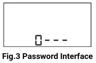
- Press the button to increase the value of the blinking digit and to decrease the value; when the first digit is set, press to move the cursor;
- Repeat the same procedure
 to set the digits from 2 nds to 4 th ;
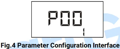
 - If the password is right, enter into the parameter configuration interface (as shown below) which includes the serial number of the set items and their parameters; press to scroll down and to scroll up;
 4) Press to set the current item, and when the first digit starts blinking, use the same way that is used for a password to enter the set value.
 4) Press
Attention:
a) Please change the controller parameters when the generator is in standby mode only (e. g. Crank disconnect conditions selection, configurable input, configurable output, various delays), otherwise, shutdown and other abnormal conditions may happen.
b) the Serial number of parameters please reference Table 7
c) The value of each parameter can be set only within a certain range; otherwise, it can’t be changed.
d) Over voltage set value must be higher than under voltage set value, otherwise over voltage and under voltage condition may occur simultaneously.
e) Over speed set value must be higher than under speed set value, otherwise over speed and under speed condition may occur simultaneously.
f) Please set the generator frequency value as low as possible when cranking, in order to make the starter be separated quickly as soon as a crank disconnects.
g) Before selecting the fuel level sensor type, it is necessary to set a configurable input port type as 8 first.
h) At any time press![]() can stop the current parameter setting immediately.
can stop the current parameter setting immediately.
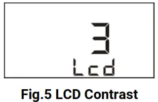
8.2. LCD CONTRAST ADJUSTMENT
When genset is in standby status, simultaneously hold and press![]() and
and![]() keys for 2s to enter into the LCD contrast adjustment interface, and LCD contrast increases one level every 1s without releasing buttons. There are 6 levels to select as requirements.
keys for 2s to enter into the LCD contrast adjustment interface, and LCD contrast increases one level every 1s without releasing buttons. There are 6 levels to select as requirements.
8.3. GENERATOR FLYWHEEL TEETH AUTOMATIC ADJUSTMENT
In manual mode, if crank disconnect conditions are selected as “2 Speed + Generator Frequency” or “5 Generator Frequency + Speed + Oil Pressure” (generator frequency and speed are not 0), the controller will automatically adjust generator flywheel teeth based on gen frequency and poles when simultaneous press![]() and
and![]() keys for 0.5s.
keys for 0.5s.
SENSOR SETTINGS
a) Sensors connected to the controller are all resistor types. Parts of build-in standard sensor curves in the controller can be selected by users via PC software (details please to see Table 10)
b) When inputting the sensor curve, X value (resistor) must be input from small to large, otherwise, a mistake occurs.
c) If the sensor type is set as “not used”, the sensor curve is not working and the LCD displays “—”.
d) If there is only a low oil pressure alarm switch and without an oil pressure sensor, a pressure sensor can be set as “low digital input is active” or “high digital input is active”.
e) The headmost or backmost values in the vertical coordinates can be set as the same as below,
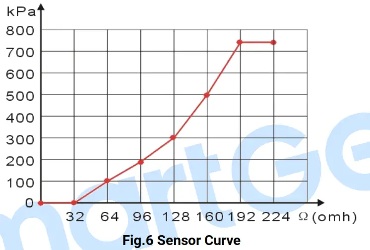
Table 12 Normal Pressure Unit Conversion Table
| N/m2 (pa) | kgf/cm2 | bar | psi | |
| 1Pa | 1 | 1.02×10⁻⁵ | 1×10⁻⁵ | 1.45×10⁻⁴ |
| 1kgf/cm2 | 9.8×10⁴ | 1 | 0.98 | 14.2 |
| 1bar | 1×10⁵ | 1.02 | 1 | 14.5 |
| 1psi | 6.89×10³ | 7.03×10⁻² | 6.89×10⁻² | 1 |
COMMISSIONING
Please make sure the following checks are made before commissioning,
- Ensure all the connections are correct and the wire diameter is suitable.
- Ensure that the controller DC power has fused, and the controller’s positive and negative are correctly connected to starting battery.
- Take proper action to prevent the engine to crank success (e. g. Remove the connection wire of the fuel valve). If checking is OK, make the starting battery power on; choose the manual mode and the controller will executive routine.
- Set the controller under manual mode, press the “start” button, and Genset will start. After the cranking times as setting, the controller will send a signal of Start Failure; then press “stop” to reset the controller.
- Recover the action to prevent the engine to crank success (e. g. Connect the wire of the fuel valve), press the start button again, and Genset will start. If everything goes well, Genset will normal running after idle running (if the idle run is set). During this time, please watch for the engine’s running situation and the AC generator’s voltage and frequency. If abnormal, stop Genset and check all wires connection according to this manual.
- Any other questions please contact with SmartGen service personnel.
TYPICAL APPLICATION
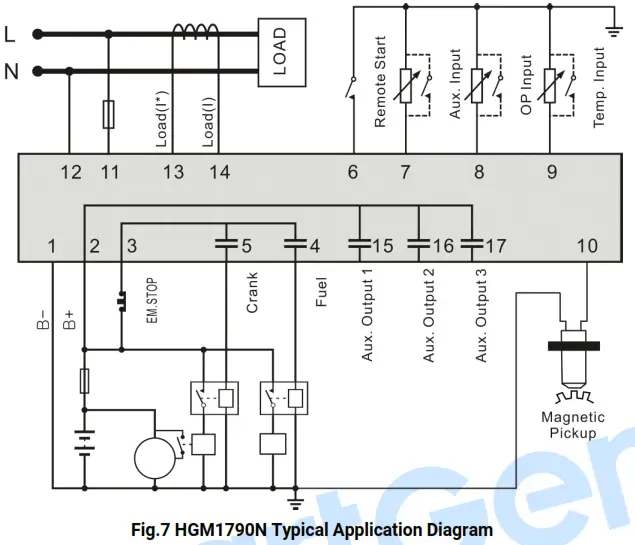
CAUTION: Crank and fuel output ports should be extended to large-capacity relays.
CAUTION: When the sensor port is configured as “high digital input is active”, hanging in the air means a high electrical level; and a power supply positive is prohibited to be connected.
INSTALLATION
12.1. FIXING CLIPS
- The controller is a panel built-in design; it is fixed by clips when installed.
- Withdraw the fixing clip screw (turn anticlockwise) until it reaches the proper position.
- Pull the fixing clip backward (towards the back of the module) ensuring two clips are inside their allotted slots.
- Turn the fixing clip screws clockwise until they are fixed on the panel.
![]() NOTE: Care should be taken not to over-tighten the screws of fixing clips.
NOTE: Care should be taken not to over-tighten the screws of fixing clips.
12.2. OVERALL DIMENSION
- BATTERY VOLTAGE INPUT HGM1790N
a series controller can suit a wide range of battery voltage DC(8~35)V. The negative of the battery must be connected with the engine shell. The diameter of the wire that connects the power supply to the battery must be over 1.5mm 2. If the floating charger is configured, please first connect the output wires of the charger to the battery’s positive and negative direction, then, connect wires from the battery’s positive and negative to the controller’s positive and negative input ports in order to prevent the charger disturbing the controller’s normal working. - SPEED SENSOR INPUT
The speed sensor is the magnetic equipment that is installed in the starter for detecting flywheel teeth. Its connection wires to the controller should apply for 2 cores shielding line. The shielding layer should connect to the No. 1 terminal in the controller while another side is hanging in the air. The else two signal wires are connected to No.1 and No.10 terminals in the controller. The output voltage of the speed sensor should be within AC(1~24)V (effective value) during the full speed. AC12V is recommended (in rated speed). When installing the speed sensor, let the sensor is spun to contacting flywheel first, then, port out 1/3 lap, and lock the nuts of the sensor at last. - OUTPUT AND EXPAND RELAYS
All outputs of the controller are relay contact output types. If need to expand the relays, please add a freewheel diode to both ends of expanding relay’s coils (when coils of the relay have DC current) or, increase the resistance-capacitance return circuit (when coils of the relay have AC current), in order to prevent disturbance to controller or others equipment. - AC INPUT
The current input of the controller must be connected to the outside current transformer. And the current transformer’s secondary side current must be 5A. At the same time, the phases of the current transformer and input voltage must be correct. Otherwise, the current of collecting and active power maybe not be correct. WARNING: When there is a load current, the transformer’s secondary side is prohibited to open the circuit.
 - WITHSTAND VOLTAGE TEST
When the controller had been installed in the control panel, if need a high voltage test, please disconnect the controller’s all terminal connections, in order to prevent high voltage into the controller and damaging it.
FAULT FINDING
Table 13 Fault Finding
| Symptoms | Possible Solutions |
| The controller no respond with power. | Check starting batteries; Check controller connection wirings; Check DC fuse. |
| Genset shutdown | Check whether the water/cylinder temperature is too high or not; Check the Genset AC voltage; Check the DC fuse. |
| Low oil pressure alarm after crank disconnect | Check the oil pressure sensor and its connections. |
| High water temp. alarm after crank disconnect | Check the temperature sensor and its connections. |
| Shutdown alarm in running | Check the related switch and its connections according to the information on the LCD; Check programmable inputs. |
| Crank not disconnect | Check fuel circuit and its connections; Check starting batteries; Check the speed sensor and its connections; Refer to the engine manual. |
| Starter no response | Check starter connections; Check starting batteries. |


