SmartGen AIN16-C Marine Engine Controllers User Manual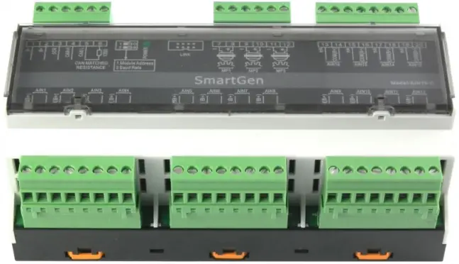
Smartgen — make your generator smart
Smartgen Technology Co., Ltd.
No. 28 Jinsuo Road
Zhengzhou City
P. R. China
Tel: +86-371-67988888
+86-371-67981888
+86-371-67991553
+86-371-67992951
+86-371-67981000 (overseas)
Fax: 0086-371-67992952
Web: http://www.smartgen.com.cn/
http://www.smartgen.cn/
Email: [email protected]
All rights reserved. No part of this publication may be reproduced in any material form (including photocopying or storing in any medium by electronic means or other) without the written permission of the copyright holder.
Smartgen Technology reserves the right to change the contents of this document without prior notice.
If the colors of actual products are different from the manual, please take the actual product as the standard.
Software Version
| Date | Version | Content |
| 2014-06-16 | 1.0 | Original release. |
This manual is suitable for AIN16-C Analog Input Module only.
Clarification of notation used within this publication.
SIGN | INSTRUCTION |
| Highlights an essential element of a procedure to ensure correctness. |
| Indicates a procedure or practice, which, if not strictly observed, could result in damage or destruction of equipment. |
| Indicates error operation may cause death, serious injury and significant property damage. |
 NOTE
NOTE CAUTION!
 WARNING!
OVERVIEW
AIN16-C analog input module is an expansion module which has 16 analog input channels and each channel is 4mA~20mA current sensor input. The data are transmitted to the HMC9000 controller for processing via CANBUS port. Different alarm threshold values can be set for each sensor via HMC9000 controller, enabling module to basically meet all kinds of customer demands.
PERFORMANCE AND CHARACTERISTICS
- With ARM-based 32-bit SCM, high integration of hardware and more reliable;
- Must be used with HMC9000 together;
- CANBUS communication baud rate can be set as 250kbps or 125kbps via dial switch;
- Module address can be set as 1 or 2.
- Widely power supply range DC(18~35)V, suitable to different starting battery voltage environment;
- 35mm rail mounting type;
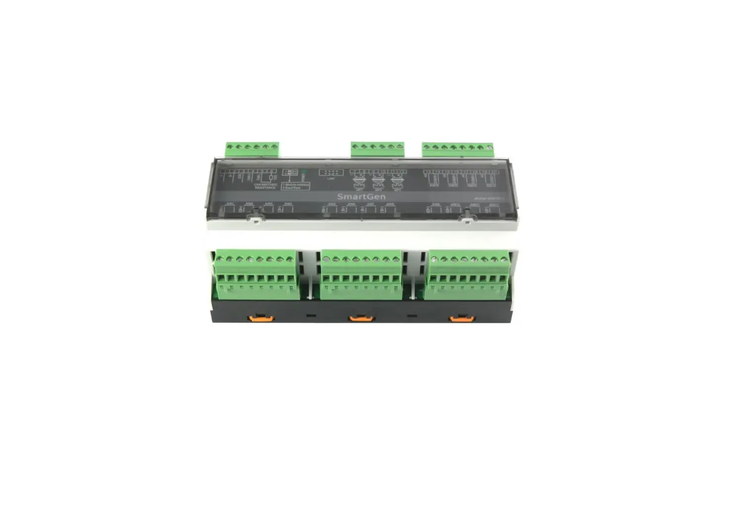
- Modular design, pluggable terminal, compact structure with easy installation.
TECHNICAL PARAMETERS
| Item | Content |
| Working Voltage | DC18.0V~35.0V continuous power supply |
| Power Consumption | <0.5W |
| Sensor Type | 4mA~20mA; Current type |
| Measurement Accuracy Class | Class 0.25 |
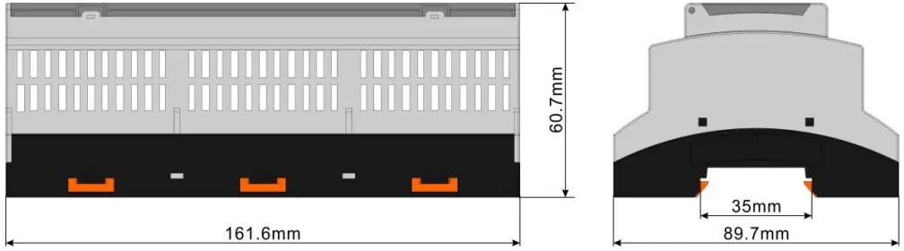
| Case Dimension | 161.6mm x 89.7mm x 60.7mm |
| Rail Dimension | 35mm |
| Working Conditions | Temp.:(-25~+70)°C Humidity:(20~93)%RH |
| Storage Conditions | Temp.:(-25~+70)°C |
| Weight | 0.33kg |
CONNECTION
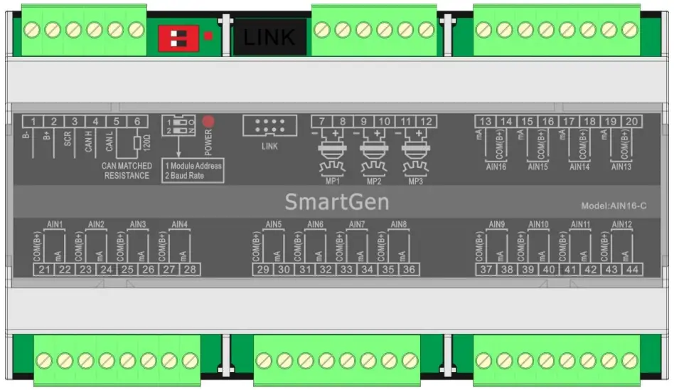
| No. | Function | Cable Size | Description | |||||
| 1 | B- | 1.0mm2 | DC power supply negative input. | |||||
| 2 | B+ | 1.0mm2 | DC power supply positive input. | |||||
| 3 | SCR | 0.5mm2 | CANBUS shielding wire; shielding wire with its one end grounded is recommended. | |||||
| 4 | CAN(H) | 0.5mm2 | A CANBUS port which communicate with HMC9000 controller. | |||||
| 5 | CAN(L) | |||||||
| 6 | 120Ω | 0.5mm2 | If needed, circuits. | make | terminal | 5, | 6 | short |
| 7 | MP1(-) | 0.5mm2 | Connected with Speed sensor, shielding line is recommended. (B-) has already connected internally. | |||||
| 8 | MP1(+) | 0.5mm2 | ||||||
| 9 | MP2(-) | 0.5mm2 | Connected with Speed sensor, shielding line is recommended. (B-) has already connected internally. | |||||
| 10 | MP2(+) | 0.5mm2 | ||||||
| 11 | MP3(-) | 0.5mm2 | Connected with Speed sensor, shielding line is recommended. (B-) has already connected internally. | |||||
| 12 | MP3(+) | 0.5mm2 | ||||||
| 13 | AIN16(mA) | 0.5mm2 | (4-20)mA analog input; | |||||
| 14 | AIN16(Com(B+)) | B+ voltage output; (Provide power for Pressure Transmitter). | ||||||
| 15 | AIN15(mA) | 0.5mm2 | (4-20)mA analog input; | |||||
| 16 | AIN15(Com(B+)) | B+ voltage output; (Provide power for Pressure Transmitter). | ||||||
| No. | Function | Cable Size | Description |
| 17 | AIN14(mA) | 0.5mm2 | (4-20)mA analog input; |
| 18 | AIN14(Com(B+)) | B+ voltage output; (Provide power for Pressure Transmitter). | |
| 19 | AIN13(mA) | 0.5mm2 | (4-20)mA analog input; |
| 20 | AIN13(Com(B+)) | B+ voltage output; (Provide power for Pressure Transmitter). | |
| 21 | AIN1(Com(B+)) | 0.5mm2 | B+ voltage output; (Provide power for Pressure Transmitter). |
| 22 | AIN1(mA) | (4-20)mA analog input; | |
| 23 | AIN2(Com(B+)) | 0.5mm2 | B+ voltage output; (Provide power for Pressure Transmitter). |
| 24 | AIN2(mA) | (4-20)mA analog input; | |
| 25 | AIN3(Com(B+)) | 0.5mm2 | B+ voltage output; (Provide power for Pressure Transmitter). |
| 26 | AIN3(mA) | (4-20)mA analog input; | |
| 27 | AIN4(Com(B+)) | 0.5mm2 | B+ voltage output; (Provide power for Pressure Transmitter). |
| 28 | AIN4(mA) | (4-20)mA analog input; | |
| 29 | AIN5(Com(B+)) | 0.5mm2 | B+ voltage output; (Provide power for Pressure Transmitter). |
| 30 | AIN5(mA) | (4-20)mA analog input; | |
| 31 | AIN6(Com(B+)) | 0.5mm2 | B+ voltage output; (Provide power for Pressure Transmitter). |
| 32 | AIN6(mA) | (4-20)mA analog input; | |
| 33 | AIN7(Com(B+)) | 0.5mm2 | B+ voltage output; (Provide power for Pressure Transmitter). |
| 34 | AIN7(mA) | (4-20)mA analog input; | |
| 35 | AIN8(Com(B+)) | 0.5mm2 | B+ voltage output; (Provide power for Pressure Transmitter). |
| 36 | AIN8(mA) | (4-20)mA analog input; | |
| 37 | AIN9(Com(B+)) | 0.5mm2 | B+ voltage output; (Provide power for Pressure Transmitter). |
| 38 | AIN9(mA) | (4-20)mA analog input; | |
| 39 | AIN10(Com(B+)) | 0.5mm2 | B+ voltage output; (Provide power for Pressure Transmitter). |
| 40 | AIN10(mA) | (4-20)mA analog input; | |
| 41 | AIN11(Com(B+)) | 0.5mm2 | B+ voltage output; (Provide power for Pressure Transmitter). |
| 42 | AIN11(mA) | (4-20)mA analog input; | |
| 43 | AIN12(Com(B+)) | 0.5mm2 | B+ voltage output; (Provide power for Pressure Transmitter). |
| 44 | AIN12(mA) | (4-20)mA analog input; | |
| SWITCH | HMC9000 can connect to two AIN16-C modules at the | ||
| No. | Function | Cable Size | Description |
| same time. Address selection:It is module 1 when the switch 1 is connected to terminal 12 while module 2 when connect to ON terminal. Baud rate selection: It is 250kbps when the switch 2 is connected to terminal 12 while 125kbps when connect to ON terminal. | |||
| POWER | Power supply indicator and communication status indicator; It is flashing when the communication is abnormal. | ||
| LINK | System upgrade port ; modify the default parameters. | ||
PROTECTION
All data can be protected via HMC9000 controller. HMC9000 can connect to two AIN16-C modules at the same time and users can select module address via dial switch. Following parameters can be set via HMC9000:
- AIN16-C module enable: HMC9000 can communicate with the module and collect the AIN16-C data only when the module is enabled;
- Alarm threshold and alarm enable of each sensor;
AIN16-C can collect data only and all alarms are initiated by HMC9000 controller.
HMC9000 will initiate alarm when the sensor value is abnormal. There are two kinds of alarm: warning alarm and shutdown alarm. All alarms are handled by HMC9000 controller only.
WARNING
Warning types are as follows:
| No. | Items | Range | Description |
| 1 | Sensor 1~16 high | From “Waiting for load” delay to “Cooling” delay | When the controller detects the sensor 1-16 warning signals, it will initiate a warning alarm and the corresponding alarm information will be displayed on LCD. |
| 2 | Sensor 1~16 Low | From “Waiting for load” delay to “Cooling” delay | |
| 3 | Sensor 1~16 open | Always active. |
SHUTDOWN ALARM
Shutdown types are as follows,
| NO. | Items | DET Range | Description |
| 1 | Sensor 1~16 High | From “Waiting for load” delay to “Cooling” delay | When the controller detects the sensor 1-16 shutdown alarm, it will initiate a shutdown alarm and the corresponding alarm information will be displayed on LCD. |
| 2 | Sensor 1~16 Low | From “Waiting for load” delay to “Cooling” delay |
PARAMETER CONFIGURATION
AIN16-C parameters can be set via HMC9000 controller or HMC9000 PC software; more details please refer to specific instruction of HMC9000.
Parameter Configuration List
| Parameter | Contents | Default |
| Module Enable | 0:Enable 1:Disable | Disable |
| Sensor 1~16 set | Sensor types/ Alarm Speed /Range/ High Shutdown Enable / High Shutdown Value / High Shutdown Delay / Low Shutdown Enable / Low Shutdown Value / Low Shutdown Delay / High Warn Enable / High Warn Value / High Return Value / High Warn Delay/ Low Warn Enable / Low Warn Value / Low Return Value / Low Warn Delay For more details please refer to chapter 5.4 | Sensor type: Temperature Sensor |
SENSOR SETTINGS
| NO. | Items | Contents | Remarks |
| 1 | Sensor types | 0:Not Used 1:Oil Pressure Sensor 2:Temperature Sensor | |
| 2 | Sensor Curve | 4-20mA | |
| 3 | Alarm Speed | (0-200)% | |
| 4 | Range (current type) | (0-6000)kpa | |
| 5 | High Shutdown Enable | 0:Enable 1:Disable | |
| 6 | High Shutdown Value | (0-6000) | |
| 7 | High Shutdown Delay | (0-3600)s | |
| 8 | Low Shutdown Enable | 0:Enable 1:Disable | |
| 9 | Low Shutdown Value | (0-6000) | |
| 10 | Low Shutdown Delay | (0-3600)s | |
| 11 | High Warn Enable | 0:Enable 1:Disable | |
| 12 | High Warn Value | (0-6000) | |
| 13 | High Return Value | (0-6000) | |
| 14 | High Warn Delay | (0-3600)s | |
| 15 | Low Warn Enable | 0:Enable 1:Disable | |
| 16 | Low Warn Value | (0-6000) | |
| 17 | Low Return Value | (0-6000) | |
| 18 | Low Warn Delay | (0-3600)s | |
| 19 | User-defined string | User can reset the sensors’ names which are displayed on HMC9000 LCD. e.g. rename sensor 1 as Temperature sensor. User-defined string can be edited via HMC9000 PC software only. | |
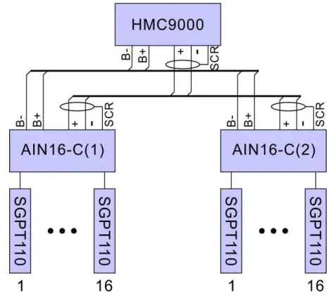
ELECTRICAL CONNECTIONS
AIN16-C ELECTRICAL CONNECTION
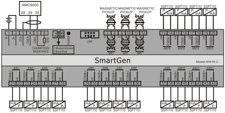
HMC9000 controller connect with two AIN16-C module
INSTALLATION
Case dimensions:
TROUBLESHOOTING
| PROBLEM | POSSIBLE SOLUTION |
| Controller no response with power. | Check batteries; Check controller connection wirings; Check DC fuse. |
| CANBUS communication failure | Check if CANBUS wires are connected in the opposite way. |