SmartGen AIN24-2 Analog Input Module
SmartGen — make your generator smart
- SmartGen Technology Co., Ltd. No.28 Jinsuo Road, Zhengzhou, Henan Province, China
- Tel: +86-371-67988888/67981888/67992951 +86-371-67981000(overseas)
- Fax: +86-371-67992952
- Email: [email protected]
- Web: www.smartgen.com.cn
- www.smartgen.cn
All rights reserved. No part of this publication may be reproduced in any material form (including photocopying or storing in any medium by electronic means or other) without the written permission of the copyright holder.
SmartGen Technology reserves the right to change the contents of this document without prior notice
Table 1 – Software Version
- Date /Version /Content
- 2021-10-26 1.0 Original release
Table 2 – Notation Clarification
| Symbol | Instruction |
| NOTE | Highlights an essential element of a procedure to ensure correctness. |
| CAUTION | Indicates a procedure or practice, which, if not strictly observed, could result in damage or destruction of equipment. |
| WARNING | Indicates a procedure or practice, which could result in injury to personnel or loss of life if not followed correctly. |
OVERVIEW
AIN24-2 Analog Input Module is a module which has 14-way K-type thermocouple sensor, 5-way resistance type sensor and 5-way (4-20)mA current type sensor. The sampling data are transmitted to the master controller via RS485 port.
PERFORMANCE AND CHARACTERISTICS
- With 32-bit ARM based SCM, high integration of hardware and more reliable;
- Must be used with master controller together;
- RS485 communication baud rate can be set as 9600bps or 19200bps via dial switch;
- Module address can be set as 1 or 2;
- Wide power supply range DC(8~35)V, suitable to different battery voltage environment;
- 35mm guide rail mounting type;
- Modular design, pluggable terminal, compact structure and easy installation.
TECHNICAL PARAMETERS
Table 3 – Technical Parameters
| Item | Content |
| Working Voltage | DC(8~35)V, continuous power supply |
| Power Consumption | <0.5W |
| K-type Thermocouple Measurement Accuracy | 1°C |
| (4-20)mA Current Measurement Accuracy | Class 1 |
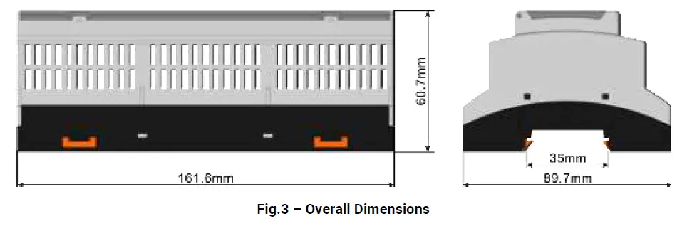
| Case Dimension | 161.6mm x 89.7mm x 60.7mm |
| Rail Dimension | 35mm |
| Working Temperature | (-25~+70)°C |
| Working Humidity | (20~93)%RH |
| Storage Temperature | (-40~+80)°C |
| Weight | 0.33kg |
WIRE CONNECTION
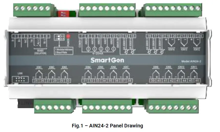
Table 4 – Terminal Connection
| No. | Function | Cable Size | Description |
| 1 | B- | 1.0mm2 | DC power supply negative input. |
| 2 | B+ | 1.0mm2 | DC power supply positive input. |
| 3 | NC | No Contact. | |
| 4 | TR | 0.5mm2 | Short connect Terminal 4 and Terminal 5 if the matched resistance is required. |
| 5 | RS485 A(+) | 0.5mm2 | The RS485 port for communication with master controller. 120Ω shielding wire with its one end grounded is recommended. |
| 6 | RS485 B(-) | ||
| 7 | COM (B+) | 1.0mm2 | 4-20mA current sensor COM terminal (B+) |
| 8 | AIN24 | 0.5mm2 | 4-20mA current sensor terminal |
| 9 | AIN23 | 0.5mm2 | 4-20mA current sensor terminal |
| 10 | AIN22 | 0.5mm2 | 4-20mA current sensor terminal |
| 11 | AIN21 | 0.5mm2 | 4-20mA current sensor terminal |
| 12 | AIN20 | 0.5mm2 | 4-20mA current sensor terminal |
| 13 | SENSOR COM | 0.5mm2 | Resistance sensor COM terminal (B+) |
| 14 | AUX.SENSOR 19 | 0.5mm2 | Resistance sensor terminal |
| 15 | AUX.SENSOR 18 | 0.5mm2 | Resistance sensor terminal |
| 16 | AUX.SENSOR 17 | 0.5mm2 | Resistance sensor terminal |
| 17 | AUX.SENSOR 16 | 0.5mm2 | Resistance sensor terminal |
| 18 | AUX.SENSOR 15 | 0.5mm2 | Resistance sensor terminal |
| 19 | KIN14+ | 0.5mm2 | “K-type” thermocouple sensor |
| 20 | KIN14- |
| No. | Function | Cable Size | Description |
| 21 | KIN13+ | 0.5mm2 | “K-type” thermocouple sensor |
| 22 | KIN13- | ||
| 23 | KIN12+ | 0.5mm2 | “K-type” thermocouple sensor |
| 24 | KIN12- | ||
| 25 | KIN1- | 0.5mm2 | “K-type” thermocouple sensor |
| 26 | KIN1+ | ||
| 27 | KIN2- | 0.5mm2 | “K-type” thermocouple sensor |
| 28 | KIN2+ | ||
| 29 | KIN3- | 0.5mm2 | “K-type” thermocouple sensor |
| 30 | KIN3+ | ||
| 31 | KIN4- | 0.5mm2 | “K-type” thermocouple sensor |
| 32 | KIN4+ | ||
| 33 | KIN5- | 0.5mm2 | “K-type” thermocouple sensor |
| 34 | KIN5+ | ||
| 35 | KIN6- | 0.5mm2 | “K-type” thermocouple sensor |
| 36 | KIN6+ | ||
| 37 | KIN7- | 0.5mm2 | “K-type” thermocouple sensor |
| 38 | KIN7+ | ||
| 39 | KIN8- | 0.5mm2 | “K-type” thermocouple sensor |
| 40 | KIN8+ | ||
| 41 | KIN9- | 0.5mm2 | “K-type” thermocouple sensor |
| 42 | KIN9+ | ||
| 43 | KIN10- | 0.5mm2 | “K-type” thermocouple sensor |
| 44 | KIN10+ | ||
| 45 | KIN11- | 0.5mm2 | “K-type” thermocouple sensor |
| 46 | KIN11+ | ||
|
SWITCH | The master controller can connect to two AIN24-2 modules at the same time. Address selection: It is module 1 when the switch 1 is connected to 12 while module 2 when connect to ON position. Baud rate selection: It is 9600bps when the switch 2 is connected to 12 while 19200bps when connect to ON position. | ||
| POWER | Power supply normal indicator; It is flashing when the communication is abnormal for over 10s. | ||
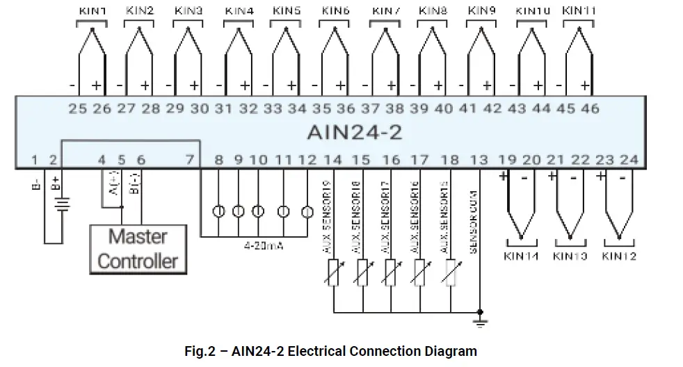
ELECTRICAL CONNECTION DIAGRAM
CASE DIMENSIONS
TROUBLESHOOTING
| Problem | Possible Solution |
| Controller no response with power | Check power voltage; Check controller connection wirings; Check DC fuse. |
| RS485 communication failure | Check if RS485 wires are connected correctly. |


