SmartGen DOUT16B-2 Digital Output Module
DOUT16B-2 DIGITAL OUTPUT MODULE
Product Information
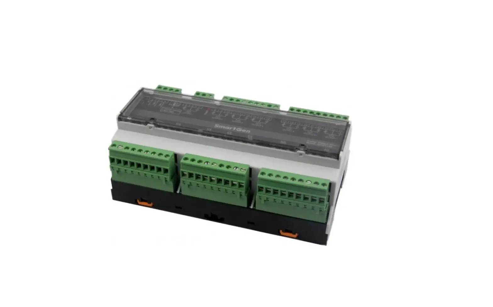
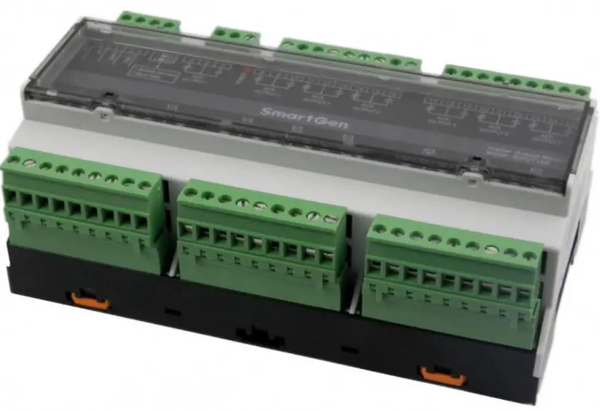
The DOUT16B-2 Digital Output Module is an expansion module that consists of 16 auxiliary digital output channels. The expansion module status is transmitted to DOUT16B-2 by the main control board via RS485. The product is manufactured by SmartGen Technology Co., Ltd., located in Zhengzhou, China.
The module has a working voltage range of DC8.0V to DC35.0V, which can provide continuous power supply to the module. The product has a compact design and can be installed easily. It is designed to work in a wide range of temperatures and humidities, making it suitable for various applications.
Product Usage Instructions
To use the DOUT16B-2 Digital Output Module, follow the steps below:
- Connect the main control board with the DOUT16B-2 module via RS485 communication port.
- Provide continuous power supply of DC8.0V to DC35.0V to the module.
- Use the auxiliary relay output ports 1-16 to connect with external devices that need to be controlled by the module.
- Use the information frame format example provided in the user manual to communicate with the module via RS485 communication port.
It is important to note that the product manual provides information on the software version and technical parameters of the product. It is also recommended to follow the installation and usage instructions provided in the user manual to ensure the proper functioning of the product.
SmartGen — make your generator smart
SmartGen Technology Co., Ltd.
No.28 Jinsuo Road
Zhengzhou
P. R. China
Tel: +86-371-67988888/67981888/67992951
+86-371-67981000(overseas)
Fax: +86-371-67992952
Web: www.smartgen.com.cn/
www.smartgen.cn/
Email: [email protected]
All rights reserved. No part of this publication may be reproduced in any material form (including photocopying or storing in any medium by electronic means or other) without the written permission of the copyright holder.
Applications for the copyright holder’s written permission to reproduce any part of this publication should be addressed to Smartgen Technology at the address above.
Any reference to trademarked product names used within this publication is owned by their respective companies.
SmartGen Technology reserves the right to change the contents of this document without prior notice.
Table 1 Software Version
| Date | Version | Note |
| 2020-10-16 | 1.0 | Original Release |
| 2020-12-15 | 1.1 | Replaced the panel drawing. |
| 2022-08-22 | 1.2 | Update company logo and manual format. |
OVERVIEW
DOUT16B-2 Digital Output Module is an expansion module which has 16 auxiliary digital output channels. Expansion module status is transmitted to DOUT16B-2 by main control board via RS485.
TECHNICAL PARAMETERS
Table 2 Technical Parameters
| Items | Contents |
| Working Voltage | DC8.0V~ DC35.0V continuous power supply |
| Power Consumption | <6W |
| Aux. relay output port 1-16 | 10A relay for output port 1~4, 7~14. 16A relay for output port 5~6, 15~16. |
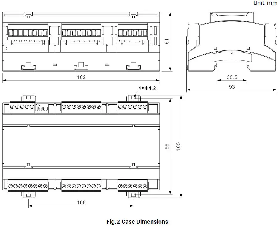
| Case Dimension | 161.6mm x 89.7mm x 60.7mm |
| Installation Way | 35mm guide-rail installation or screw installation |
| Working Temperature | (-25~+70)ºC |
| Working Humidity | (20~93)%RH |
| Storage Temperature | (-30~+80)ºC |
| Weight | 0.4kg |
MODULE ADDRESS
This is a 4-bit in-line DIP switch with 16 coding status, namely 16 module addresses (from 100 to 115). When it is turned to ON, the status is 1. The module address formula is Module Address=1A+2B+4C+8D+100. For example, when ABCD is 0000, the module address is 100. When ABCD is 1000, the module address is 101. When ABCD is 0100, the module address is 102. Similarly, when ABCD is 1111, the module address is 115. The corresponding module addresses of DIP switch
Table 3 Module Addresses
| A | B | C | D | Module Addresses |
| 0 | 0 | 0 | 0 | 100 |
| 1 | 0 | 0 | 0 | 101 |
| 0 | 1 | 0 | 0 | 102 |
| 1 | 1 | 0 | 0 | 103 |
| 0 | 0 | 1 | 0 | 104 |
| 1 | 0 | 1 | 0 | 105 |
| 0 | 1 | 1 | 0 | 106 |
| 1 | 1 | 1 | 0 | 107 |
| 0 | 0 | 0 | 1 | 108 |
| 1 | 0 | 0 | 1 | 109 |
| 0 | 1 | 0 | 1 | 110 |
| 1 | 1 | 0 | 1 | 111 |
| 0 | 0 | 1 | 1 | 112 |
| 1 | 0 | 1 | 1 | 113 |
| 0 | 1 | 1 | 1 | 114 |
| 1 | 1 | 1 | 1 | 115 |
TERMINAL DIAGRAM 
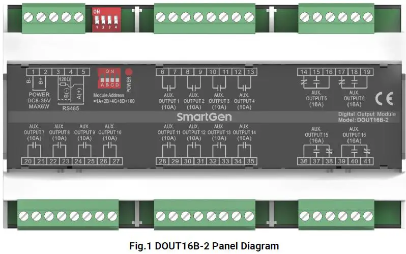
Table 1 Description of Rear Panel Terminal Connection
| No. | Name | Description | Cable Size | Remarks |
| 1. | B- | DC power supply negative input | 1.5mm2 | DC power supply negative input. |
| 2. | B+ | DC power supply positive input | 1.5mm2 | DC power supply positive input. |
| 3. | 120Ω | RS485 communication port |
0.5 mm2 | Twisted shielded line is used. If the terminal needs to match 120Ω resistance, terminal 3 and 4 need to be short circuited. |
| 4. | RS485B (-) | |||
| 5. | RS485A (+) | |||
| 6. | Aux. output port 1 | Volt free relay N/O output | 1.5 mm2 | Capacity 250VAC/10A. |
| 7. | ||||
| 8. | Aux. output port 2 | Volt free relay N/O output | 1.5mm2 | Capacity 250VAC/10A. |
| 9. | ||||
| 10. | Aux. output port 3 | Volt free relay N/O output | 1.5mm2 | |
| 11. | Capacity 250VAC/10A. | |||
| 12. | Aux. output port 4 | Volt free relay N/O output | 1.5mm2 | |
| 13. | ||||
| 14. | Aux. output port 5 | N/C | 2.5mm2 | Capacity 250VAC/16A. |
| 15. | N/O | |||
| 16. | Common | |||
| 17. | Aux. output port 6 | N/C | 2.5mm2 | Capacity 250VAC/16A. |
| 18. | N/O | |||
| 19. | Common | |||
| 20. | Aux. output port 7 | Volt free relay N/O output | 1.5mm2 | Capacity 250VAC/10A. |
| 21. |
| No. | Name | Description | Cable Size | Remarks |
| 22. | Aux. output port 8 | Volt free relay N/O output | 1.5mm2 | Capacity 250VAC/10A. |
| 23. | ||||
| 24. | Aux. output port 9 | Volt free relay N/O output | 1.5mm2 | Capacity 250VAC/10A. |
| 25. | ||||
| 26. | Aux. output port 10 | Volt free relay N/O output | 1.5mm2 | Capacity 250VAC/10A. |
| 27. | ||||
| 28. | Aux. output port 11 | Volt free relay N/O output | 1.5mm2 | Capacity 250VAC/10A. |
| 29. | ||||
| 30. | Aux. output port 12 | Volt free relay N/O output | 1.5mm2 | Capacity 250VAC/10A. |
| 31. | ||||
| 32. | Aux. output port 13 | Volt free relay N/O output | 1.5mm2 | Capacity 250VAC/10A. |
| 33. | ||||
| 34. | Aux. output port 14 | Volt free relay N/O output | 1.5mm2 | Capacity 250VAC/10A. |
| 35. | ||||
| 36. | Aux. output port 15 | Common | 2.5mm2 | Capacity 250VAC/16A. |
| 37. | N/O | |||
| 38. | N/C | |||
| 39. | Aux. output port 16 | Common | 2.5mm2 | Capacity 250VAC/16A. |
| 40. | N/O | |||
| 41. | N/C | |||
| POWER | Power indicator | Light when power supply is normal, distinguish when abnormal. | ||
| Module Address | Module address | Select module address by DIP switch. |
COMMUNICATION CONFIGURATION AND MODBUS COMMUNICATION PROTOCOL
RS485 COMMUNICATION PORT
DOUT16B-2 is an expansion output module with RS485 communication port, which follows Modbus-RTU communication protocol.
Communication Parameters
Module Address 100 (range 100-115)
Baud Rate 9600bps
Data Bit 8-bit
Parity Bit None
Stop Bit 2-bit
INFORMATION FRAME FORMAT EXAMPLE
FUNCTION CODE 01H
Slave address is 64H (decimal 100), read 10H (decimal 16) status of starting address 64H (decimal 100).
Table 2 Function Code 01H Master Request Example
| Request | Bytes | Example (Hex) |
| Slave address | 1 | 64 Send to slave 100 |
| Function code | 1 | 01 Read status |
| Starting address | 2 | 00 Starting address is 100 64 |
| Count number | 2 | 00 Read 16 status 10 |
| CRC code | 2 | 75 CRC code which calculated by master EC |
Table 3 Function Code 01H Slave Response Example
| Response | Bytes | Example (Hex) |
| Slave address | 1 | 64 Respond slave address 100 |
| Function code | 1 | 01 Read status |
| Read count | 1 | 02 16 status (total 2 bytes) |
| Data 1 | 1 | 01 The content of address 07-00 |
| Data 2 | 1 | 00 The content of address 0F-08 |
| CRC code | 2 | F4 CRC code which calculated by slave. 64 |
The value of status 07-00 is indicated as 01H in Hex, and 00000001 in binary. Status 07 is the high-order byte, 00 is the low-order byte. The state of status 07-00 is OFF-OFF-OFF-OFF-OFF-OFF-OFF-ON.
FUNCTION CODE 03H
Slave address is 64H (decimal 100), starting address is 1 data of 64H (decimal 100) (2 bytes per data).
Table 4 Example Data Address
| Address | Data (Hex) |
| 64H | 1 |
Table 5 Function Code 03H Master Request Example
| Request | Bytes | Example (Hex) |
| Slave address | 1 | 64 Send to the slave 64H |
| Function code | 1 | 03 Read point register |
| Starting address | 2 | 00 Starting address is 64H 64 |
| Count Number | 2 | 00 Read 1 data (total 2 bytes) 01 |
| CRC code | 2 | CC CRC code which calculated by master. 20 |
Table 6 Function Code 03H Slave Response Example
| Response | Bytes | Example (Hex) |
| Slave address | 1 | 64 Respond to the slave 64H |
| Function code | 1 | 03 Read point register |
| Read count | 1 | 02 1 data (total 2 bytes) |
| Data 1 | 2 | 00 The content of address 0064H 01 |
| CRC code | 2 | 35 CRC code which calculated by slave. 8C |
FUNCTION CODE 05H
Slave address is 64H (decimal 100), starting address is one status of 64H (decimal 100). Set 64H unit as 1.
Table 7 Example Status Data Address
| Address | Data(Hex) |
| 64H | 1 |
Illustration: Hex value FF00 forced status is 1. 0000H is forced as 0. Other values are illegal and do not affect the status.
Table 8 Function Code 05H Master Request Example
| Request | Bytes | Example (Hex) |
| Slave address | 1 | 64 Send to the slave 64H |
| Function code | 1 | 05 Forced status |
| Starting address | 2 | 00 Starting address is 0064H 64 |
| Data | 2 | FF Set status as 1 00 |
| CRC code | 2 | C4 CRC code which calculated by master. 10 |
Table 9 Function Code 05H Slave Response Example
| Response | Bytes | Example (Hex) |
| Slave address | 1 | 64 Send to the slave 64H |
| Function code | 1 | 05 Forced status |
| Starting address | 2 | 00 Starting address is 0064H 64 |
| Data | 2 | FF Set status as 1 00 |
| CRC code | 2 | C4 CRC code which calculated by master. 10 |
FUNCTION CODE 06H
Slave address is 64H (decimal 100), set one point content of starting address 64H (decimal 100) as 0001H.
Table 10 Function Code 06H Master Request Example
| Request | Bytes | Example (Hex) |
| Slave address | 1 | 64 Send to the slave 64H |
| Function code | 1 | 06 Write single register |
| Starting address | 2 | 00 Starting address is 0064H 64 |
| Data | 2 | 00 Set 1 point data (total 2 bytes) 01 |
| CRC code | 2 | 00 CRC code which calculated by master. 20 |
Table 11 Function Code 06H Slave Response Example
| Response | Bytes | Example (Hex) |
| Slave address | 1 | 64 Send to the slave 64H |
| Function code | 1 | 06 Write single register |
| Starting address | 2 | 00 Starting address is 0064H 64 |
| Data | 2 | 00 Set 1 point data (total 2 bytes) 01 |
| CRC code | 2 | 00 CRC code which calculated by master. 20 |
CORRESPONDING ADDRESS TO FUNCTION CODE
Table 12 Function Code 01H
| Address | Item | Description |
| 100 | Output Port 1 Status | 1 for active |
| 101 | Output Port 2 Status | 1 for active |
| 102 | Output Port 3 Status | 1 for active |
| 103 | Output Port 4 Status | 1 for active |
| 104 | Output Port 5 Status | 1 for active |
| 105 | Output Port 6 Status | 1 for active |
| 106 | Output Port 7 Status | 1 for active |
| 107 | Output Port 8 Status | 1 for active |
| 108 | Output Port 9 Status | 1 for active |
| 109 | Output Port 10 Status | 1 for active |
| 110 | Output Port 11 Status | 1 for active |
| 111 | Output Port 12 Status | 1 for active |
| 112 | Output Port 13 Status | 1 for active |
| 113 | Output Port 14 Status | 1 for active |
| 114 | Output Port 15 Status | 1 for active |
| 115 | Output Port 16 Status | 1 for active |
Table 13 Function Code 05H
| Address | Item | Description |
| 100 | Output Port 1 Status | 1 for active |
| 101 | Output Port 2 Status | 1 for active |
| 102 | Output Port 3 Status | 1 for active |
| 103 | Output Port 4 Status | 1 for active |
| 104 | Output Port 5 Status | 1 for active |
| 105 | Output Port 6 Status | 1 for active |
| 106 | Output Port 7 Status | 1 for active |
| 107 | Output Port 8 Status | 1 for active |
| 108 | Output Port 9 Status | 1 for active |
| 109 | Output Port 10 Status | 1 for active |
| 110 | Output Port 11 Status | 1 for active |
| 111 | Output Port 12 Status | 1 for active |
| 112 | Output Port 13 Status | 1 for active |
| 113 | Output Port 14 Status | 1 for active |
| 114 | Output Port 15 Status | 1 for active |
| 115 | Output Port 16 Status | 1 for active |
Table 14 Function Code 03H, 06H
| Address | Item | Description | Bytes |
| 100 | Output Port 1-16 Status | Unsigned | 2Byte |