NIUV35LTE Smart Central Controller
User Manual

1. Overview
1.1 Scope of application
This ECU is designed mainly for overseas development, and is compatible with the MGT (High version) models.
2. Mechanical properties
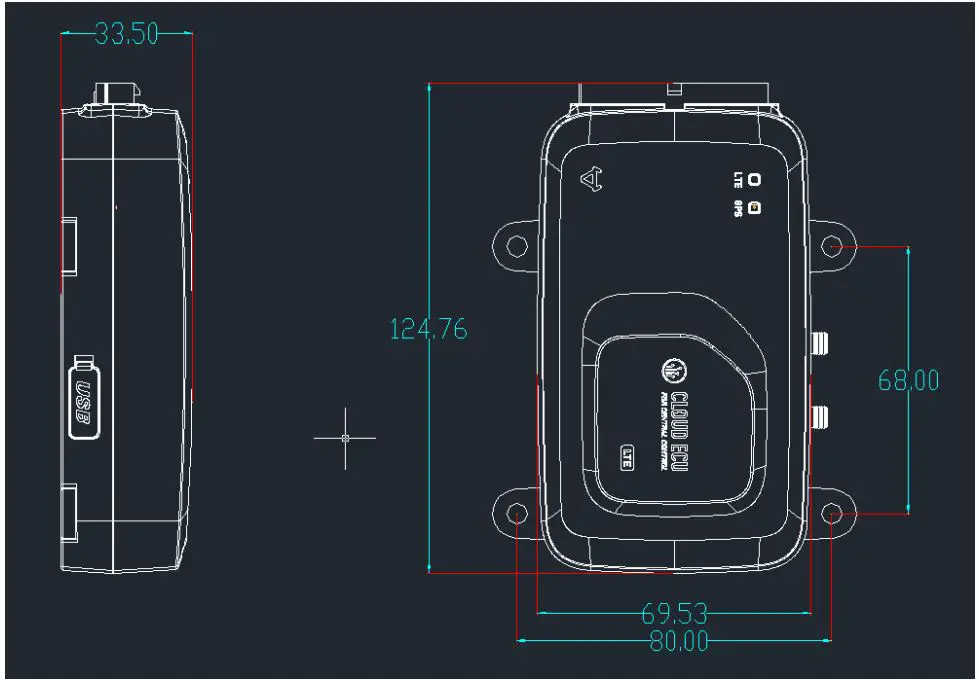
2.1 Shape and Dimensions
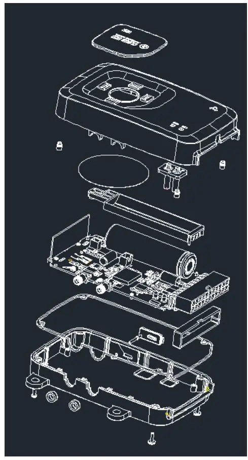
2.2 Exploded view
2.3 Mechanical parameters
- Shell material, color code PP black
- PCB thickness: 2mm
- Type of fixing screw: black, cross recessed self-tapping screw
3 Electrical characteristics
3.1 Electrical parameters
3.1.1 power supply
| Item | Value | Work scope | remark |
| Supply voltage | 48V | 36-100V | |
| Electric current | 15mA | <200mA | 48V |
3.1.2 Signal
- Electric door lock signal
| Item | parameters |
| Signal type | High and low |
| Voltage scope | < 55V |
| logic | 0 (0V~15V) 1 (37V~70V) |
| Input resistance | 51K |
| Input current | >0.1mA |
| Logic trip voltage | 20V |
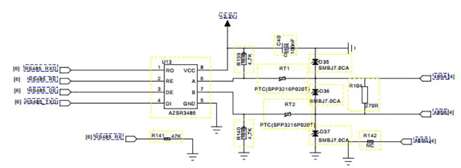
- 485 Circuit Circuit diagram
- Battery parameters
| Item | Parameters |
| Nominal capacity | 2200mAh |
| Model | 18650 |
| Rated voltage | 3.7V |
| Charging cut-off voltage | 4.2V |
| Discharge cut-off voltage | 3V |
| Maximum charging current | 1100mA |
| Standard continuous discharge current | 440mA |
- Charging
| Item | Parameters |
| Input power | 5V |
| Input current | 200mA |
| Trickle charge current | 50mA |
| Constant current charging current | 200mA |
| Constant voltage charging voltage | 4.2V |
| Temperature protection | 125°C |
3.2 Module parameters
3.2.1 GPS Module
- Frequency range
- Supply voltage 3V
- Impedance 50Ω
- Gain
- Positioning time
- Cold start 40s(under open conditions)
- Hot start 5s(under open conditions)
3.2.2 4G Module
| Module | LTE | UMTS | GSM |
| EC25-E | FDD: B1/B3/B5/B7/B8/B20 TDD: B38/B40/B41 | WCDMA:B1/B5/B8 | 900/1800MHz |
| EC25-A | FDD: B2/B4/B12 | WCDMA:B2/B4/B5 |
3.2.2 433MHz Module
- Frequency range: central frequency band 433MHz
- Supply power voltage: 8~3.6V
- OOK demodulation
- Data rate:0~5.0kbps
- Sensitivity:-109dBm(3.0kbps),1%BER
- Receiver bandwidth:330/200kHz
- Periodic operation(2s/3ms)
4 Features
4.1 Function Description
The ECU is the host on the vehicle, including 485 communication module, 4G communication module, GPS positioning module, ACC detection module, small battery charging module, power supply module, six-axis gyroscope module, power management module, which can realize GPS positioning, and Network communication between servers, charge and discharge management of small batteries in the central control, vehicle attitude, acceleration detection and vehicle power management.
4.2 Functional Overview
4.2.1 Interact with cloud server through 4G module
Receive remote cloud commands , Collect vehicle data, and send some or all of the data to the cloud when the event is triggered
4.2.2 Vehicle power management
The central control can directly manage the power supply of the vast majority of the equipment of the entire vehicle, and prohibit the operation of the vehicle under special circumstances such as theft
4.2.3 Motor controller control
The ECU can communicate with the motor controller through 485. When one key is started, the central control exchanges the verification code with the motor controller. If the verification code is out of date, the motor controller runs at full speed; during the driving process, the central control queries the motor controller in real time Data, and related calculations; when one-click is started, the central control uploads the motor controller serial number, and the server verifies whether the serial number is stolen through the product library.
4.2.4 BMS Control
The ECU uses different intervals to query BMS data when the vehicle is running or parking. During one-key activation, the central control uploads the BMS serial number, and the server verifies whether the serial number is stolen through the product library.
4.2.5 Display of Dashboard data
The ECU calculates the speed and mileage through the rotation speed, obtains the time through GPS and RTC, reads the SOC through BMS, and analyzes the status of BMS and motor controller, and controls the instrument to display the time, speed, mileage, SOC, driving status, and fault code.
4.2.6 Display of Charging Time
The central control judges whether to enter the charging state by current, time and BMS status, and displays the charging time on the instrument in time.
4.2.7 Low battery speed limit
When the power is less than 10%, the central control motor controller limits the speed to the first gear.
4.2.8 Remote Control Vehicle
The APP can control the central locking, unlocking, arming, disarming, starting, shutting down, car searching, alarming, etc. through the cloud remote command.
4.2.9 GPS Positing
The ECU can be positioned through the GPS module, and obtain and upload the latitude and longitude, time, heading, positioning error, satellite data data.
4.2.10 Vehicle data transmission
The ECU can control the 4G module to transmit vehicle data to the remote server through the 4G network.
4.2.11 Transaction alarm
The ECU monitors the status of the vehicle in real-time in the parking state, and uploads the data in time when it is detected that the vehicle has fallen or moved.
4.2.12 Robbery data verification
The ECU can upload the serial number of BMS, motor controller, central control and SIM card when the electric door is opened. The server side matches the uploaded serial number with the robbery serial number. Send a car lock order.
4.2.13 Battery removal report
When the main battery is removed, the ECU uploads the battery removal information.
4.2.14 Main battery sleep
When the main battery is powered off, the ECU enters a low-power mode, controls the GPS, 4G module, and single-chip microcomputer to sleep to achieve the longest standby time.
4.2.15 A-gps
Automatically download ephemeris data to achieve seconds.
4.2.16 485 offline upgrade
Through H1 equipment, offline upgrade.
4.2.17 FOTA
Over-the-air upgrade through differential packages. Achieve faster upgrade speed.
4.2.18 Set upload template remotely
The server can arbitrarily define the rules for uploading data in the central control.
4.2.19 Update any data remotely
The server can remotely update any data in the central control data table.
4.2.20 Battery power-on prompt tone
A reminder tone is broadcast when the battery is connected to the vehicle.
4.2.21 Battery charging start tone
When the battery begins to enter the charging state, it will announce a sound.
4.2.22 Battery charging end sound
A reminder tone will be broadcast when the battery is fully charged.
4.2.23 Alarm status changes and uploads to the server actively
When the status of the alarm changes, it will actively trigger a synchronous update.
4.2.24 Shutdown without speed overtime
When ACC is turned on and there is no vehicle speed for 8 minutes, the central control controller automatically turns off ACC.
4.2.25 Bluetooth function
You can start, close, arm and release operations via Bluetooth.
4.2.26 Data storage
Server address, secret key, ESN, vibration detection threshold, mileage, low battery speed limit value data storage, alarm associated state, and will not be lost when upgrading the version.
4.2.27 Charging is prohibited
- The riding status does not respond to the remote control
4.2.28 Vibration detection
When vibration is detected in the central control, a vibration alarm is reported. The vibration detection threshold can be set.
4.2.29 Dump detection
Use Gsensor to determine whether the vehicle tilt exceeds 60 °, and when it exceeds 60 °, report a dump alarm.
4.2.30 Sheepfold (electronic fence)
After the electric door is closed, the central control records the latitude and longitude of the parking. When GPS wakes up, compare the distance between real-time positioning and parking latitude and longitude. When the distance exceeds the set value, an electronic fence alarm is reported.
4.2.31 Remote control to modify vibration sensitivity function
After long-pressing the start button for 5s, the 1-5 gear switches back and forth and the prompt sound.
4.2.32 Command code matching
Send commands via remote or 485, the central control enters the remote control code matching mode, press the remote control to perform code matching.
4.2.33 Battery warehouse inspection (Hall signal)
When detecting that the battery is absent, security information will be reported to the network.
4.2.34 Seat cushion detection (Hall signal)
When it is detected that the seat cushion is opened, security information will be reported to the network.
5 Status and Task Descriptions
5.1 Detailed status and description
| Vehicle Status | Descriptions | 4G Module | GPS | 485 |
| Ready to boot | When the remote | The ECU sends a command to the lock | ||
| control start-stop | control(LKU) to make the LKU enter the | |||
| button is pressed, the | ready-to-start state. 30s after entering | |||
| central control will | the ready-to-start state, if the central | |||
| send data to the lock | control detects that the faucet lock is | |||
| control and the whole | open at this time, it will power on, if it | |||
| machine enters the | does not detect that the faucet lock is | |||
| state of ready to start. | open after 30S, the central control will | |||
| issue a command to the lock control to | ||||
| let the lock control exit the preparation | ||||
| Power on state. | ||||
| Illegal electric door | After arming, if you | |||
| opened | don’t press the | |||
| remote control | ||||
| start-stop button, if | ||||
| you open the faucet | ||||
| lock directly, it will | ||||
| alarm. | ||||
| Power on | Motor controller serial number and central control verification | Upload vehicle serial number information (MEI, telephone number, motor controller serial number, BMS serial number, central control serial number) | Turn on | Communicate with the motor controller, query the serial number of the motor controller once every 100ms, check with the CRC algorithm after success, enter the main program after success, communicate with the BMS and motor controller, and obtain data. |
| Driving | Real-time query data, display instrument | Upload location information to the server every 5s and vehicle information every 60s | Turn on | Communicate with a device every 100ms (a total of 300ms is required for the instrument, motor controller, and BMS to complete a cycle). |
| Power off | After shutting down | Upload vehicle status data | Turn on 90s | Save mileage, clear the status bits of BMS |
| through the faucet | before sending | and motor controller (see protocol for | ||
| lock, the central | data, then turn | details) | ||
| control will save the | off | |||
| mileage and report | ||||
| the status |
| parking | With B a t t e r y | Parking | Real-time monitoring, reporting vehicle status and location | When not sending data, the 4G module enters low power consumption mode and exits low power consumption mode each time data is sent. Turn on the first 4h, then upload location information every 5min, and upload vehicle information every 15min. | Turn on | It communicates with the BMS every 5 minutes in the first 2 hours, and every 15 minutes thereafter. |
| Alarming | When proactively alarming, upload data quickly | Upload location information every 6s | Turn on | |||
| Transaction | Anti-theft / reminder (when the electric door lock is closed, the central control is moved or dumped) | When dumping, the data is continuously uploaded 5 times every 15 minutes. When moving, it is detected that the data is uploaded once. | Turn on | |||
| Write data | Communicate with the host computer through the data line | The state remains unchanged. After writing the data, the central control starts the network function and uploads the data. | Turn on | Become slave state. Can communicate with quality inspection software, production line software, and boot upgrade software. | ||
| Remove the battery | sleep | Lowest power consumption operation, guarantee the longest running time | Upload location information every 15min, then close | Turn on 60s after wake up, then turn off | Module off |
5.2 Data upload frequency
| Vehicle Status | Send Frequency | GPS switch |
| ACC ON | GPS data: 5 seconds, system data: 10 seconds | Keep on |
| ACC OFF | GPS data: 600 seconds, system data: 1200 seconds | Close after the data upload is completed, open the GPS 120s before uploading the data |
| Transaction alarm status | GPS data: 3 seconds, system data: none | Keep on |
| Alarm state | Alarm status changes, upload immediately, then 3 seconds | Turn on the GPS when you touch the alarm. After the alarm is over, restore the previous time setting |
| Pull out the battery alarm | GPS data 900 seconds; system data: none | After the central control wakes up, turn on for 60 seconds |
5.3 Communication protocol
- In-vehicle communication 485 communication protocol see, “Maverick Electric Communication Protocol”, “Controller Command Table”, “BMS Communication Protocol”, “Instrument Communication Protocol”
- For the network communication protocol, please refer to “Definition of Central Control Data Exchange”
5.4 Abnormal state
- When the other electronic equipment of the vehicle is in an abnormal state, the central control instrument displays the fault
- No card inserted, the central control setting instrument displays 60, and always displays
- The SIM card is in arrears, the central control setting instrument displays 67, and the screen is cleared after
- After being in the position without GPS signal for a long time, and the central control is completely powered off, the central control cannot get the correct time
- Input overvoltage, under voltage will cause the central control to burn out, or the power supply cannot be normally supplied
5.5 Light effect description
| Blue Light | Green Light | Blue and green light always on | |
| Always on | Do not connect to the Internet | Positing Failure | Do not have SIM card |
| Always off | No such status | GPS closed | |
| Flash fast | No configuration file written (high priority) | 100ms on,1s off | |
| Flash slow | Build internet | Positing success | 100ms on,3s off |
5.6 Instrument icon effect description
![]()
| GSM Icon | |
| L02 always on L2 on | Strong signal, signal>10 |
| L02 always on L2 flash | Weak signal,signal 1~9 |
| L02 flash L2 off | No signal,0 |
| GPS Icon | |
| L01 always on L1 on | Strong signal, signal >3 |
| L01 always on L1 flash | Weak signal,signal 1~2 |
| L01 flash L1 off | No signal,0 |
6 Alarm and power management functions and sound and light effects
6.1 Description of vehicle status
| Mode | Entry conditions | Perform action |
|
Parking |
|
|
|
Fortification |
|
|
|
Unlock |
|
|
|
Start | 1. In other modes besides the start mode, press the start-stop button of the remote control to enter the ready-to-start state, and start the faucet lock within 30S |
|
| Search | 1. Enter by command | 1. Blink left and right turn signal to prompt 10s, and then play car search sound for 20s |
|
Vibration alarm | 1. Under the state of fortification, illegally touch the vehicle 2. Enter by command |
|
|
Wheel alarm | 1. In the fortified state, the hub rotation triggers * Note: The wheel motion alarm detects the motor phase input signal. When the hub is stationary, the motor phase signal does not change. After the lock motor signal is enabled, the motor phase signal fluctuates, and the phase signal detection should be stopped |
|
|
Illegal electric door opened Call the police | 1. Under the fortified state, the mechanical electric door lock is triggered to open |
|
6.2 Sound effect definition
| Name | Description |
| Start tone | 1kHz 0.05s + pause 0.04s + 1.35kHz-0.05s + pause 0.04s + 1.55kHz 0.05s |
| Parking sound | 1.55kHz 0.05s + pause 0.02s + 1.35kHz 0.05s + pause 0.02s + 1kHz 0.05s |
| Lock tone | 1kHz 0.05s + 1.5kHz 0.05s + 1kHz 0.05s; |
| Unlock tone | (1kHz 0.05s + 1.2kHz 0.05s + 1.2kHz 0.05s + pause 0.1s) Loop 2 times; |
| Search tone | (1.5kHz 0.05s + 1kHz 0.05s + 1.5kHz 0.05s + pause 0.1s) loop;(Once double flash once) |
| Alarm tone | (1.5kHz 0.05s + 1kHz 0.05s + 1.5kHz 0.05s + pause 0.1s) Loop 20 times; |
| Operation prompt tone |
(1kHz 0.05s + pause 0.03s) Loop 2 times |
6.3 Lighting definition
| Status | Left/right turn light | Headlight / tail lights | Buzzer sound effect |
| Fortification | Turns off after 3s | Turns off after 3s | The same as the sound effect of the specification |
| Disarm | Flashes 2 times at 1s intervals and goes off | Turns off after 2s | The same as the sound effect of the specification |
| Vibration / wheel alarm | Flashes 10 times at 1s intervals and goes off | Steady off after 10s | The same as the sound effect of the specification, stop after 10s |
|
Search |
Blink 20 times at 1s intervals, off |
Turns off after 20s | There is no sound in the first 10s, and the sound effect in the second 10s is the same as the specification, and the 10s stops |
| Turn on | off | off | The same as the sound effect of the specification |
| Turn off | off | off | The same as the sound effect of the specification |
7 Notes on OTA upgrade function
When using H1 or other tools for OTA offline upgrade, please close the door lock to operate, otherwise it will cause unpredictable failure.
8 Performance requirements
8.1 Temperature
-20 ~ + 50 ℃, the central control unit can run continuously for a long time
-30 ~ + 80 ℃, the central control unit can store for a long time
8.2 Humidity
It can work normally when the relative humidity does not exceed 100%. The central control unit should work safely when the surface temperature is lower than the dew point, even if condensation occurs on the surface.
8.3 Salt spray
Meet the relevant regulations in GB / T2423.17.
8.4 Fixed frequency vibration and sweep frequency vibration
Fix the central control unit on the vibration test platform, and perform the vibration test according to the conditions specified in the table below. During the test, there shall be no loose or damaged parts. The performance is intact after the test.
| Frequency sweep range (Hz) | Double amplitude (mm) | Frequency sweep | Period (min) |
| 10~25 | 1.5 | 16 | 45 |
8.5 Waterproof and dustproof
When raining or high-pressure water washing, the construction, installation and ventilation of the central control unit shall ensure that it will not be damaged. The central control unit shall meet the protection level requirements of IP54 products in GB / T 4942.2.
8.6 Temperature insulation resistance
In the dry environment, the insulation resistance of the central control unit is not less than 20MΩ.
8.7 Constant damp heat
The central control unit should be able to withstand a constant humid heat test at 40 ℃ ± 2 ℃, a relative humidity of 90% to 95% and a duration of 4 days. The appearance should be free of obvious corrosion and spots, the functions of the central control unit should be normal, the insulation resistance should not be less than 1 MΩ, and should comply with the provisions of e, f of this chapter.
8.8 Electrostatic discharge immunity
The table shall comply with the Class B classification specified in GB / T 17626.2.
8.9 Electromagnetic compatibility
Meet GB / T18655-2002, GB / T17619-1998.
This device complies with part 15 of the FCC Rules. Operation is subject to the condition that this device does not cause harmful interference.
This device is verified to comply with part 15 of the FCC Rules for use with cable television service.
This device complies with part 15 of the FCC Rules. Operation is subject to the following two conditions:
- This device may not cause harmful interference, and
- this device must accept any interference received, including interference that may cause undesired operation.
Please note that changes or modifications not expressly approved by the party responsible for compliance could void the user’s authority to operate the equipment.
Note: This equipment has been tested and found to comply with the limits for a Class B digital device, pursuant to part 15 of the FCC Rules. These limits are designed to provide reasonable protection against harmful interference in a residential installation. This equipment generates, uses and can radiate radio frequency energy and, if not installed and used in accordance with the instructions, may cause harmful interference to radio communications. However, there is no guarantee that interference will not occur in a particular installation. If this equipment does cause harmful interference to radio or television reception, which can be determined by turning the equipment off and on, the user is encouraged to try to correct the interference by one or more of the following measures:
—Reorient or relocate the receiving antenna.
—Increase the separation between the equipment and receiver.
—Connect the equipment into an outlet on a circuit different from that to which the receiver is connected.
—Consult the dealer or an experienced radio/TV technician for help.
This equipment complies with radio frequency exposure limits set forth by the FCC for an uncontrolled environment.
This equipment should be installed and operated with a minimum distance of 20 cm between the device and the user or bystanders.
This device must not be co-located or operating in conjunction with any other antenna or transmitter.


