![]() Smart Controller
Smart Controller
User Guide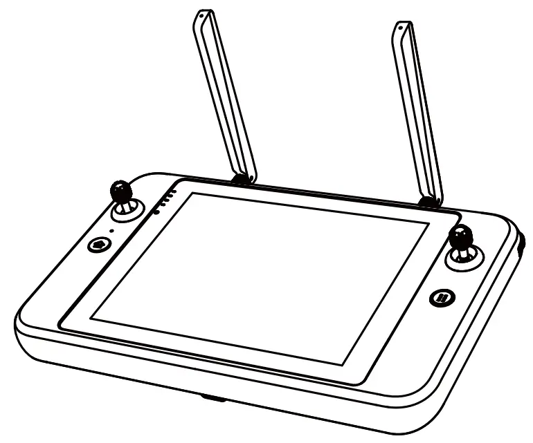
DISCLAIMER
To ensure sale and successful operation of your Autel smart remote controller, please strictly follow the operating instructions and steps in this guide. If the user does not abide by the safety operation instructions. Autel Robotics will not be responsible for any product damage or loss in use whether direct or indirect, legal, special, accident or economic loss (including but not limited to loss of profit), and does not provide warranty service. Do not use incompati-ble parts or use any method that does not comply with the official instructions of Autel Robotics to modify the product.
The safety guidelines In this document will be updated from time to time. To ensure you get the latest version. please visit the official website: htips://www.autelrobotics.com/
BATTERY SAFETY
The Autel smart remote controller is powered by a smart lithium-ion battery. Improper use of lithium-Ion batteries can be dangerous. Please ensure that the following battery usage, charging and storage guidelines are strictly followed.![]() WARNING:
WARNING:
- Only use the battery and charger provided by Autel Robotics. It is forbidden to modify the battery assembly and its charger or use third-party equipment to replace it.
- The electrolyte in the battery is extremely corrosive. It the electrolyte spills into your eyes or skin accidentally, please rinse the affected area with clean water and seek medical attention immediately.
PRECAUTIONS
When using the Autel Smart Controller (hereinafter referred to as the ‘Smart Controller), if improperly used, the aircraft may cause a certain degree of injury and damage to people and property. Please be cautious while using it. For details, please refer to the aircraft’s disclaimer and safety operation guidelines.
- Before each flight, make sure that the Smart Controller is fully charged.
- Make sure the Smart Controller antennas are unfolded and adjusted to the appropriate position to ensure the best possible flight results.
- If the Smart Controller antennas are damaged, it will affect the performance, please contact the after-sales technical support immediately.
- If the aircraft is changed, it needs to be repaired before use.
- Make sure to turn off the aircraft power before turning off the remote controller each time.
- When not in use, make sure to fully charge the smart controller every three months.
- Once the power of the smart controller is less than 10%, please charge it to prevent an over-discharge error. This is caused by long-term storage with a low battery charge. When the smart controller will not be in use for an extended time, discharge the battery between 40%-60% before storage.
- Do not block the vent of the Smart Controller to prevent overheating and diminished performance.
- Do not disassemble the smart controller. If any parts of the controller are damaged, contact Autel Robotics After-Sale Support.
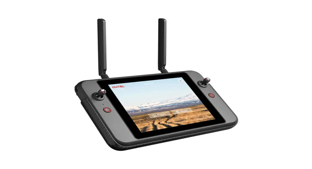
AUTEL SMART CONTROLLER
The Autel Smart Controller can be used with any supported aircraft, and It provides a high-definition real-time image transmission and ft can control the aircraft and camera up to 13km (8.08 miles) 11] communication distance. The Smart Controller has a built-in 7.9-inch 2048×1536 ultra-high-definition, ultra-bright screen with a maximum 2000nit brightness. It provides a clear image display under the bright sunlight. With its convenient, built-in 128G memory it can store your photos and videos onboard. The operating time is about 4.5 hours when the battery is fully charged and the screen is at 50% brightness.
ITEM LIST
| NO | DIAGRAM | ITEM NAME | QTY |
| 1 | 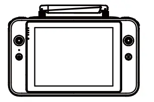 | 7.9-inch Smart controller | 1PC |
| 2 |  | Smart Controller Protective Case | 1PC |
| 3 | 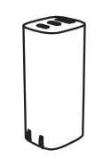 | A/C adapter | 1PC |
| 4 | 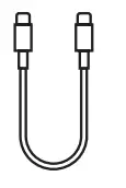 | USB Type-C cable | 1PC |
| 5 | 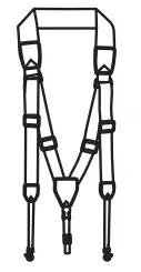 | Chest Strap | 1PC |
| 6 | 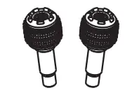 | Spare Command Sticks | 1PC |
| 7 |  | Documentation (Quick Start Guide) | 1PC |
[1] Fly in an open, unobstructed, electromagnetic interference-free environment. The smart controller can reach the maximum communication distance under FCC standards. The actual distance may be less based on the local flight environment.
[2] The above-mentioned working time is measured in a laboratory environment at room temperature. The battery life will vary In different usage scenarios.
CONTROLLER LAYOUT
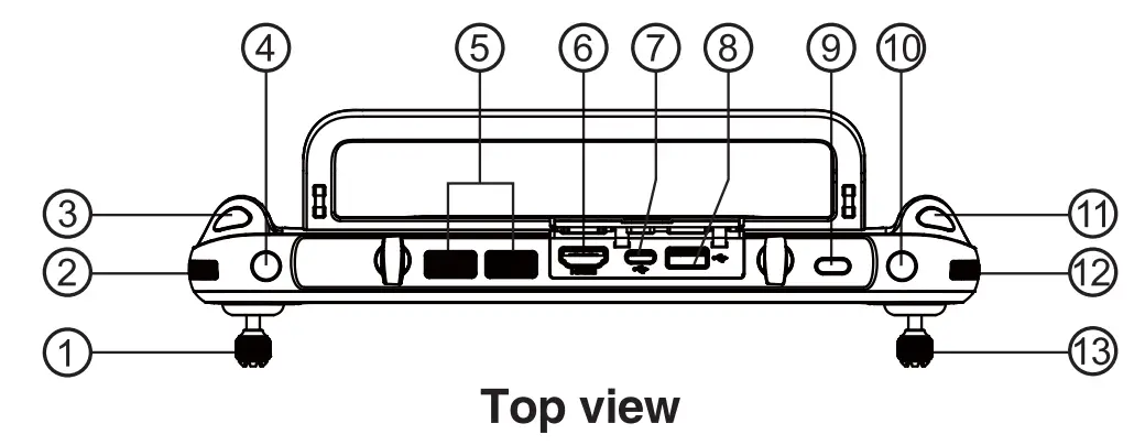
- Left Command Stick
- Gimbal Pitch Angle Wheel
- Video Recording Button
- Customizable Button C1
- Air Outlet
- HDMI Port
- USB TYPE-C Port
- USB TYPE-A Port
- Power Button
- Customizable Button C2
- Photo Shutter Button
- Zoom Control Wheel
- Right Command Stick
‘The function may alter, please take the practical effect as standard.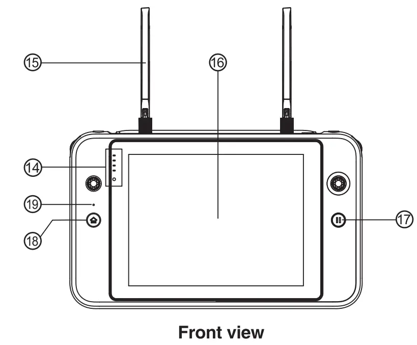
- Battery Indicator
- Antenna
- Touch Screen
- Pause Button
- Return to Home (RTH) Button
- Microphone
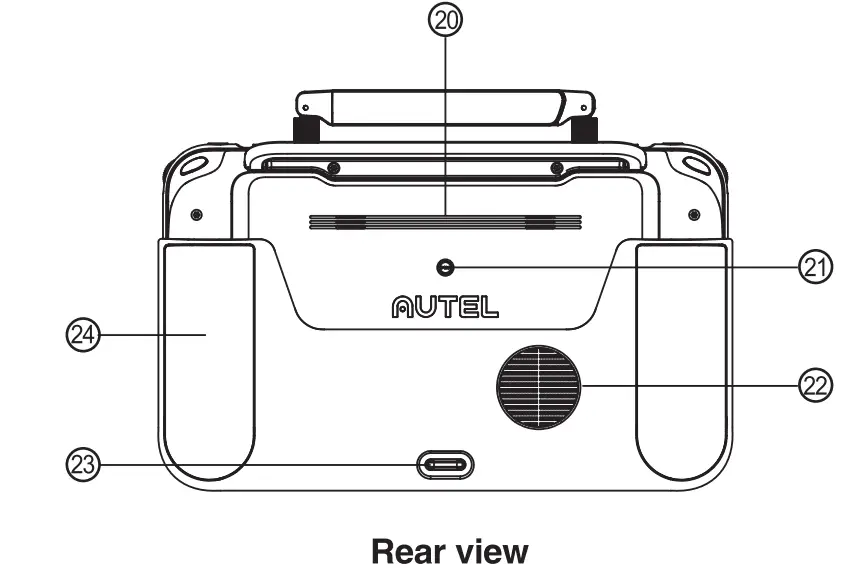 Speaker hole
- Tripod Mount Hole
- Air Vent
- Bottom Hook
- Grips
POWER ON THE SMART CONTROLLER
7.1 Check Battery Level
Press the power button to check the battery life
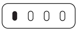 | 1 light solid on Battery ≥25% |
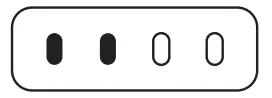 | 2 lights solid on Battery ≥50% |
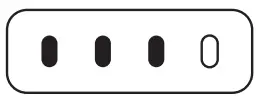 | 3 lights solid on Battery ≥75% |
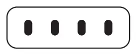 | 4 lights solid on Battery≥100% |
7.2 Powering on/off
Press and hold the power button for 2 sec to turn on and off the Smart Controller.
7.3 Charging Remote
Controller indication light status
| 1 light solid on Battery ≥25% |
| 2 lights solid on Battery ≥50% |
| 3 lights solid on Battery≥ 75% |
| 4 lights solid on Battery≥100% |
![]() NOTE: LED indicator light will blink while charging
NOTE: LED indicator light will blink while charging
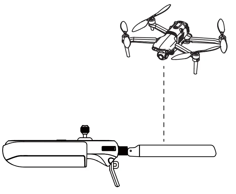
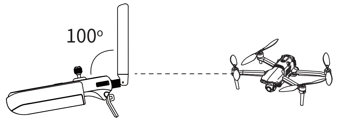
ANTENNA ADJUSTMENT
Unfold the Smart Controller antennas and adjust them to the optimal angle. The signal strength varies when the antenna angle Is different. When the antenna and the back of the remote controller are at an angle of 180° or 260°, and the antenna surface is facing the aircraft, the signal quality of the aircraft and controller will reach the optimal condition.![]() NOTE: LED indicator will flash while charging
NOTE: LED indicator will flash while charging
- Do not use other communication equipment which has the same frequency band at the same time, to avoid interference to the Smart Controller signal.
- During operation, the Autel Explorer app, will prompt the user when the image transmission signal is poor. Adjust the antenna angles according to the prompts to ensure the Smart Controller and aircraft have the best communication range.
FREQUENCY MATCH
When the Smart Controller and the aircraft are purchased as a set, the Smart Controller
has been matched to the aircraft at the factory. and it can be used directly after the aircraft is activated. If purchased separately, please use the following methods to link.
- Press (short press) the linking button next to the USS port on the right side of the aircraft body to put the aircraft into the linking mode.
- Power on the Smart Controller and run the Autel Explorer app, enter the mission flight interface, click the gear icon in the upper right corner, enter the settings menu, click ‘remote control -> data transmission and image transmission linking> start linking’, wait a few seconds until the data transmission is set correctly and the linking is a success.
FLIGHT
Open the Auto! Explore the app and enter the flight interface.
Before takeoff, place the aircraft on a flat and level surface and face the rear side of the aircraft towards you.
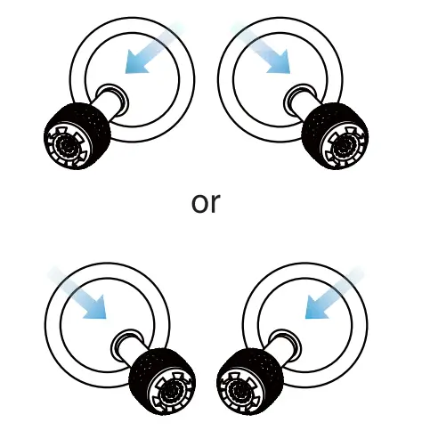
Manual takeoff and landing (Mode 2)
Toe-in or out on both command sticks for about 2 seconds to start the motors
| Manual Takeoff | |
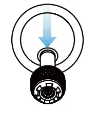
 | 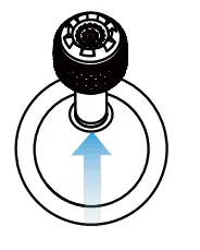 Push up slowly Left Command Stick (mode 2) |
| Manual landing | Automatic takeoff and landing |
 Push down slowly Left Command Stick (Mode 2 Push down slowly Left Command Stick (Mode 2 |  press and hold the Lake-off/landing button 3 seconds press and hold the Lake-off/landing button 3 seconds |
![]() NOTE: Before takeoff, place the aircraft on a flat and level surface and face the rear side of the aircraft towards you. Mode 2 Is the default control mode of the Smart Controller. During the flight, you can use the left stick to control the flight altitude and direction, and use the right stick to control the forward, backward, left and right directions of the aircraft. gi
NOTE: Before takeoff, place the aircraft on a flat and level surface and face the rear side of the aircraft towards you. Mode 2 Is the default control mode of the Smart Controller. During the flight, you can use the left stick to control the flight altitude and direction, and use the right stick to control the forward, backward, left and right directions of the aircraft. gi![]() NOTE:
NOTE:
- Please make sure that the Smart Controller has successfully matched with the aircraft.
- For more functions of the Smart Controller, please read the user manual for details
11. Command Stick Control (Mode 2)
Left Command Stick
| Ascend/Decend Left Side View | 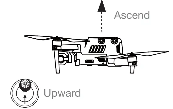 |
| Left Side View | 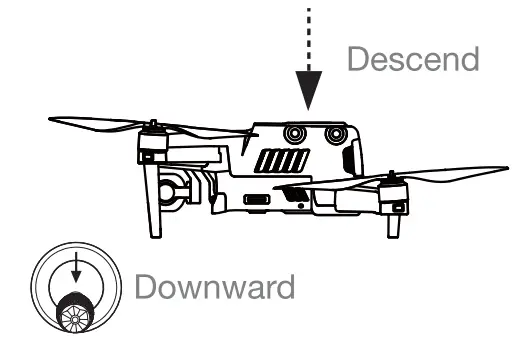 |
| Top View Nose Rotates Left | 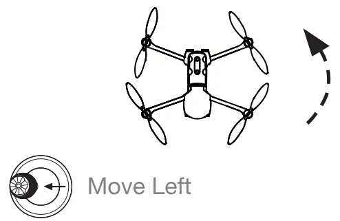 |
| Top View Nose Rotates Right | 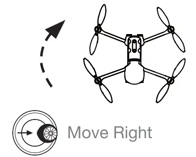 |
Right Command Stick
| Left Side View | 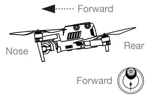 |
| Left Side View | 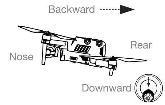 |
| Real View | 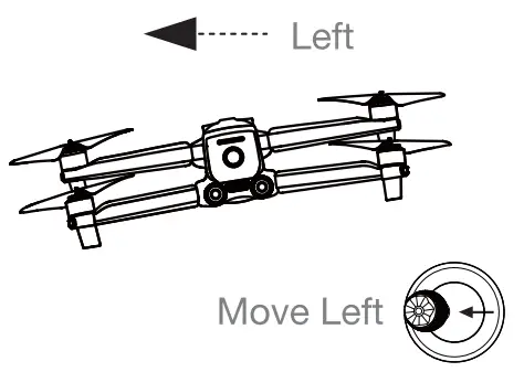 |
| Real View | 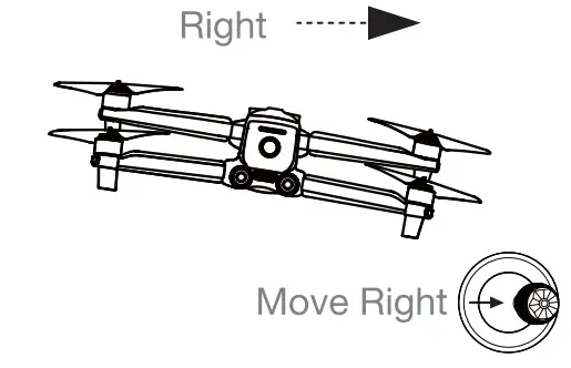 |
Specifications
Image Transmission
| Max Signal Transmission Distance (No interference, No obstacles) | FCC: 13 km CE / MIC: 7km SRRC: 7km |
Digital transmission
| Working Frequency | 5.725 – 5.755 GHz |
WI-Fl
| Protocol | Wi-Fi Direct, Wi-Fi Display, 802.11aibig/n/ac Support 2 x 2 MIMO Wi-Fi |
| Working Frequency | 2.400 – 2.4635 GHz; 5.150 – 5.250GHz; 5.650 – 5.755GHz; 5.725 – 5.850 GHz |
Other Specifications
| Battery | Name: Intelligent Li-ion battery Capacity: 5800mAh Voltage: 11.55V Battery Type: Litton Battery Energy: 67 Wh Charging time: 120 min |
| Operating Hours | – 3h (Max Brightness) – 4.5 h (50% Brightness) |
| Internal Storage | 128GB |
| Video Output port | HDMI Port |
| USB-A Voltage/Current | 5V / 2A |
| Operating Environment | -20C to 40 C |
| Temp Storage temperature | -20 C to 60 C (within a month) -20 C to 45 C (between one to three months) -20 C to 23 C (one year) |
| Charging Environment Temp | OC to40C |
| “Supported Aircrafts | EVO II Series EVO II R11( Series EVO II Enterprise |
| Satellite Positioning Module | GPS + GLONASS + Galileo |
| Dimensions | 303x190x87mm (with antenna folded) 303x273x87mm (with antenna unfolded) |
| Weight | 1150g (without protective case) 1250g (with protective case) |
![]() NOTE:
NOTE:
- When external devices are connected and powered by the remote controller, the battery life may be reduced.
- The working frequency band varies according to different countries and models.
- We will support more Autel Robotics aircraft in the future, please visit our official website https://www.autelrobotics.com/ for the latest information.
FCC Caution:
Operation of 5150-5250 MHz is restricted to indoor use only.
Any changes or modifications not expressly approved by the party responsible for compliance could void the user’s authority to operate the equipment. This device complies with part 15 ofthe FCC Rules. Operation is subject to the following two conditions: (1) This device may not cause harmful interference, and (2) this device must accept any interference received, including interference that may cause undesired operation.
IMPORTANT NOTE:
Note: This equipment has been tested and found to comply with the limits for a Class B digital device, pursuant to part 15 of the FCC Rules. These limits are designed to provide reasonable protection against harmful interference in a residential installation. This equipment generates, uses, and can radiate radio frequency energy and, if not installed and used in accordance with the instructions, may cause harmful interference to radio communications. However, there is no guarantee that interference will not occur in a particular installation. If this equipment does cause harmful reference e to radio or television reception, which can be determined by turning the equipment off and on, the user is encouraged to try to correct the interference by one or more of the following measures:
–Reorient or relocate the receiving antenna.
–Increase the separation between the equipment and receiver.
–Connect the equipment into an outlet on a circuit different from that to which the receiver is connected.
–Consult the dealer or an experienced radio/TV technician for help.
Specific Absorption Rate (SAR) information SAR tests are conducted using standard operating positions accepted by the FCC with the device transmitting at its highest certified power level in all tested frequency bands, although the SAR is determined at the highest certified power level, the actual SAR level of the device while operating can be well below the maximum value, in general, the closer you are to a wireless base station antenna, the lower the power output. Before a new model device is available for sale to the public, it must be tested and certified to the FCC that it does not exceed the exposure limit established by the FCC, Tests for each device are performed in positions and locations (e.g. at the ear and worn on the body) as required by the FCC.
For limb-worn operation, this device has been tested and meets the FCC RF exposure guidelines when used with an accessory designated for this product or when used with an accessory that contains no metal.
For body-worn operation, this device has been tested and meets the FCC RF exposure guidelines when used with an accessory designated for this product or when used with an accessory that contains no metal and that positions the device a minimum of 10mm from the body.
ISEDC Warning
Operation of 5150-5250 MHz is restricted to indoor use only.
This device complies with innovation, Science, and Economic Development Canada licence-exempt RSS standard(s). Operation is subject to the following two conditions: (1) this device may not cause interference, and (2) this device must accept any interference, including interference that may cause undesired operation of the device.
IMPORTANT NOTE: Specific Absorption Rate (SAR) information SAR tests are conducted using standard operating positions accepted by the ISEDC with the device transmitting at its highest certified power level in all tested frequency bands, although the SAR is determined at the highest certified power level, the actual SAR level of the device while operating can be well below the maximum value, in general, the closer you are to a wireless base station antenna, the lower the power output.
Before a new model device is available for sale to the public, it must be tested and certified to the ISEDC that it does not exceed the exposure limit established by the ISEDC, Tests for each device are performed in positions and locations (e.g. at the ear and worn on the body)as required by the ISEDC. For limb-worn operation, this device has been tested and meets the ISEDCRF exposure guidelines when used with an accessory designated for this product or when used with an accessory that contains no metal.
For body-worn operation, this device has been tested and meets the ISEDC RF exposure guidelines when used with an accessory designated for this product or when used with an accessory that contains no metal and that positions the device a minimum of 10mm from the body.
Steps to use electronic tags
Step1:Select”Camera”
Step2:Click the gear icon in the upper right corner, enter the settings menu
Step3:Select”Certification Mark”![]()
WWW.AUTELROBOTICS.COM
2020-2021 Autel Robotics Co., Ltd.
All Rights Reserved


