SmartGen Technology Co., Ltd.
No.28 Jinsuo Road, Zhengzhou, Henan Province, China
Tel: +86-371-67988888/67981888/67992951 +86-371-67981000(overseas)
Fax: +86-371-67992952
Web: www.smartgen.com.cn/ www.smartgen.cn/
Email: [email protected]
All rights reserved. No part of this publication may be reproduced in any material form (including photocopying or storing in any medium by electronic means or other) without the written permission of the copyright holder. Applications for the copyright holder’s written permission to reproduce any part of this publication should be addressed to SmartGen Technology at the address above. Any reference to trademarked product names used within this publication is owned by their respective companies.
SmartGen Technology reserves the right to change the contents of this document without prior notice.
Table 1 Software Version
| Sign | Instruction |
| NOTE | Highlights an essential element of a procedure to ensure correctness. |
| CAUTION! | Indicates a procedure or practice, which, if not strictly observed, could result in damage or destruction of equipment. |
OVERVIEW
HLS300A Power Share Module is a piece of upgrade product of HLS300. It is a special design for genset power share. On the basis of pre-set parameters, it can automatically complete power share in the process of genset running. Controller is upgraded to LCD graphic display, optional Chinese and English, control button and reactive power share function are added. The main function of HLS300A module is to share active power and reactive power proportionally and evenly to each operating genset based on genset capacitance. The module is easy to operate, convenient to install and can be widely used for ship genset and land genset.
PERFORMANCE AND CHARACTERISTICS
Main characteristics are as below:
- Suitable for 3-phase 3-wire, single phase 2-wire power systems with frequency 50/60Hz;
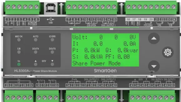
- 132×64 LCD display with backlight display, touch-button operations allowing to transfer display or set module running parameters;
- Module running parameters can be set by PC test software; module is connected with PC by USB nport in using;
- 10 relay outputs, 2 of which are used for GOV frequency raising and drop to control output, 5 are used for configurable output, 2 are used for -P, P>n% indication outputs, and 1 is used for C/B
- OPEN output control;
- 1 FIXLOAD mode, 1 UNL unloading, 1 close and 1 AUTO digital input;
- When genset is not working, press UP key longer for 3s in information display interface and it enters test mode, which can test whether LCD display, relay output and panel indicators are normal or not;
- Wide power supply range DC(8~35)V;
- Controller applies 35mm guide rail mounting;
- Modular structure design, pluggable connection terminal, compact structure with easy installation.
SPECIFICATION
Table 3 Product Parameters
| Parameter | Details |
| Working Voltage | DC8.0V to DC35.0V continuous |
| Overall Consumption | 2W (Standby mode≤1W) |
| AC Input | AC50V~ AC620V (ph-ph) |
| AC Frequency | 50Hz/60Hz |
| Relay Output | 6 10A AC250V Volt free outputs 4 5A AC250V Volt free outputs |
| CT Secondary Current | Rated: 5A |
| Working Temperature | (-25~+70)°C |
| Working Humidity | (20~95)%RH |
| Storage Temperature | (-25~+70)°C |
| Insulation Intensity | Apply AC2.2kV voltage between high voltage terminal and low voltage terminal; The leakage current is not more than 3mA within 1min. |
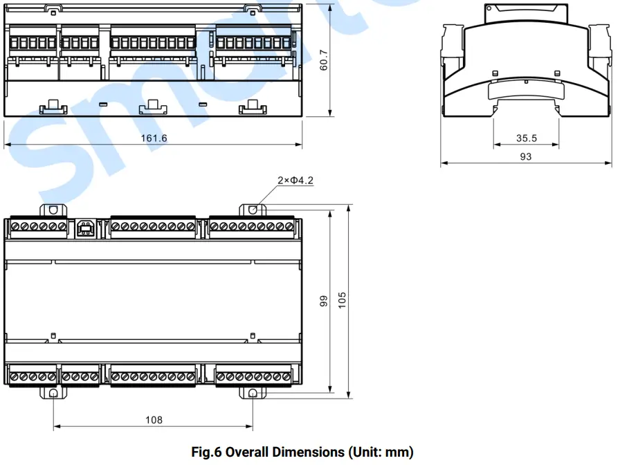
| Case Dimensions | 161.6mm x 92.94mm x 60.7mm |
| Weight | 0.49kg |
PANEL INDICATORS AND TERMINALS DESCRIPTION
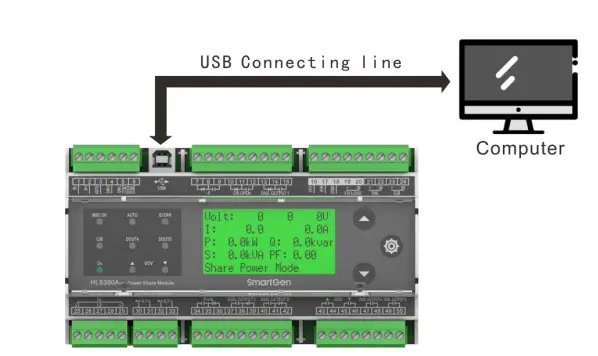
Table 4 LEDs Definition Description
| No. | Function | Size | Note | ||||
| 1 | B- | 1.5mm2 | Connected with negative of battery. | ||||
| 2 | B+ | 1.5mm2 | Connected with positive of battery. | ||||
| 3 | AUTO | 0.5mm2 | Power share is enabled when both C/B input and this input are active. | ||||
| 4 | CANH | 0.5mm2 | MSC communication. | ||||
| 5 | CANL | 0.5mm2 | |||||
| 6 | Terminal Resistor Match | If terminal resistor short connecting with No. 4 terminal is needed, otherwise hung it up. | |||||
| 7 | Reverse Power Output | Normally Close | 1.5mm2 | Output when reverse power has exceeded set value and the delay is over. | Normally contactor; free output; Rated | C/O Volts 10A | |
| 8 | COM | ||||||
| 9 | Normally Open | ||||||
| 10 | Open Output | Normally Close | 1.5mm2 | Output when open. | Normally contactor; free output; Rated | C/O Volts 10A | |
| 11 | COM | ||||||
| 12 | Normally Open | ||||||
| 13 | Digi. Output 1 | Normally Close | Configurable digital output port; can be configured to other function output. | Normally contactor; free output; Rated | C/O Volts 10A | ||
| 14 | COM | ||||||
| 15 | Normally Open | ||||||
| 16 | +5V | 1.0 mm2 | Power adjustment. | ||||
| 17 | AIN | 1.0 mm2 | |||||
| 18 | COM1 | 1.0 mm2 | |||||
| 19 | FIXLOAD | – | 1.0mm2 | Fixed power mode input, active when it is short connected. | |||
| 20 | IN | ||||||
| 21 | UNL | – | 1.0mm2 | Unload input, active when it is short connected. | |||
| 22 | IN | ||||||
| 23 | C/B | – | 1.0mm2 | Main switch close input, active when it is short connected. | |||
| 24 | IN | ||||||
| 25 | L1 Phase Voltage Input | 1.0mm2 | AC input. | ||||
| 26 | |||||||
| 27 | L2 Phase Voltage Input | 1.0mm2 | |||||
| 28 | |||||||
| 29 | L3 Phase Voltage Input | 1.0mm2 | |||||
| 30 | IL1 | CT A Phase Input | 1.5mm2 | Externally connected to secondary coil of current transformer (rated 5A). | |||
| 31 | |||||||
| 32 | IL3 | CT C Phase Input | 1.5mm2 | Externally connected to secondary coil of current transformer (rated 5A). | |||
| 33 | |||||||
Table 5 Terminal Description
| No. | Function | Size | Note | ||||
| 1 | B- | 1.5mm2 | Connected with negative of battery. | ||||
| 2 | B+ | 1.5mm2 | Connected with positive of battery. | ||||
| 3 | AUTO | 0.5mm2 | Power share is enabled when both C/B input and this input are active. | ||||
| 4 | CANH | 0.5mm2 | MSC communication. | ||||
| 5 | CANL | 0.5mm2 | |||||
| 6 | Terminal Resistor Match | If terminal resistor short connecting with No. 4 terminal is needed, otherwise hung it up. | |||||
| 7 | Reverse Power Output | Normally Close | 1.5mm2 | Output when reverse power has exceeded set value and the delay is over. | Normally contactor; free output; Rated | C/O Volts 10A | |
| 8 | COM | ||||||
| 9 | Normally Open | ||||||
| 10 | Open Output | Normally Close | 1.5mm2 | Output when open. | Normally contactor; free output; Rated | C/O Volts 10A | |
| 11 | COM | ||||||
| 12 | Normally Open | ||||||
| 13 | Digi. Output 1 | Normally Close | Configurable digital output port; can be configured to other function output. | Normally contactor; free output; Rated | C/O Volts 10A | ||
| 14 | COM | ||||||
| 15 | Normally Open | ||||||
| 16 | +5V | 1.0 mm2 | Power adjustment. | ||||
| 17 | AIN | 1.0 mm2 | |||||
| 18 | COM1 | 1.0 mm2 | |||||
| 19 | FIXLOAD | – | 1.0mm2 | Fixed power mode input, active when it is short connected. | |||
| 20 | IN | ||||||
| 21 | UNL | – | 1.0mm2 | Unload input, active when it is short connected. | |||
| 22 | IN | ||||||
| 23 | C/B | – | 1.0mm2 | Main switch close input, active when it is short connected. | |||
| 24 | IN | ||||||
| 25 | L1 Phase Voltage Input | 1.0mm2 | AC input. | ||||
| 26 | |||||||
| 27 | L2 Phase Voltage Input | 1.0mm2 | |||||
| 28 | |||||||
| 29 | L3 Phase Voltage Input | 1.0mm2 | |||||
| 30 | IL1 | CT A Phase Input | 1.5mm2 | Externally connected to secondary coil of current transformer (rated 5A). | |||
| 31 | |||||||
| 32 | IL3 | CT C Phase Input | 1.5mm2 | Externally connected to secondary coil of current transformer (rated 5A). | |||
| 33 | |||||||
NOTE: About PC programming connection, please connect PC with USB connecting wire. Through the PC software of our company, parameters can be set. Please see Fig.2
SCOPES AND DEFINITIONS OF PROGRAMMABLE PARAMETERS
Table 6 Module Configurable Parameters
| No. | Items | Parameters | Defaults | Description | |
| 1 | AC System | (0-1) | 0 | 0: 3P3W; 1: 1P2W | |
| 2 | Rated Voltage | (30-30000)V | 400 | / | |
| 3 | Volt Trans. | (0-1) | 0 | 0: Disabled; 1: Enabled | |
| 4 | Volt Trans. Primary Voltage | (30-30000)V | 100 | / | |
| 5 | Volt Trans. Secondary Voltage | (30-1000)V | 100 | / | |
| 6 | Over Volt | (0-1) | 1 | 0: Disabled; 1: Enabled | |
| 7 | (100-120)% | 115 | Threshold | ||
| 8 | (100-120)% | 113 | Returned | ||
| 9 | (0-3600)s | 3 | Delay | ||
| 10 | Under Volt | (0-1) | 1 | 0: Disabled; 1: Enabled | |
| 11 | (70-100)% | 75 | Threshold | ||
| 12 | (70-100)% | 77 | Returned | ||
| 13 | (0-3600)s | 3 | Delay | ||
| 14 | Over Freq | (0-1) | 1 | 0: Disabled; 1: Enabled | |
| 15 | (100-120)% | 110 | Threshold | ||
| 16 | (100-120)% | 104 | Returned | ||
| 17 | 3 | Delay | |||
| 18 | Under Freq | (0-1) | 1 | 0: Disabled; 1: Enabled | |
| 19 | (80-100)% | 90 | Threshold | ||
| 20 | (80-100)% | 96 | Returned | ||
| 21 | (0-3600)s | 3 | Delay | ||
| 22 | Loss of Phase | (0-1) | 1 | 0: Disabled; 1: Enabled | |
| 23 | Phase Rotation Monitor | (0-1) | 1 | 0: Disabled; 1: Enabled | |
| 24 | CT Ratio/5 | (5-6000) | 500 | / | |
| 25 | Full Load Rated Current | (5-6000)A | 500 | / | |
| 26 | Rated Active Power | (0-6000)kW | 276 | / | |
| 27 | Rated Reactive Power | (0-6000)kvar | 207 | / | |
| 28 | Reverse Power Threshold | (0-20)% | 10 | / | |
| 29 | Reverse Power Delay | (1-3600)s | 3 | / | |
| 30 | Low Power Threshold | (0-20)% | 10 | / | |
| 31 | Low Power Delay | (1-3600)s | 3 | / | |
| 32 | 20% Power Threshold | (0-50)% | 20 | Total active power/rated active power×100% ≤ the set value and duration ≥ the corresponding delay value, the output voltage signal is effective if programmable outlet configuration is P<20% . | |
| 33 | 20% Power Delay | (1-3600)s | 3 | / | |
| No. | Items | Parameters | Defaults | Description |
| 34 | 80% Power Threshold | (0-120)% | 80 | Total active power/rated active power×100% ≥ the set value and duration ≥ the corresponding delay value, the output voltage signal is effective if programmable outlet configuration is P>80%. |
| 35 | 80% Power Delay | (1-3600)s | 3 | / |
| 36 | Loss of Excitation Threshold | (0-50)% | 20 | / |
| 37 | Loss of Excitation Delay | (1-3600)s | 3 | / |
| 38 | Unbalance Threshold of Active Share | (0-50)% | 15 | / |
| 39 | Unbalance Delay of Active Share | (1-3600)s | 90 | / |
| 40 | Unbalance Threshold of Reactive Share | (0-50)% | 20 | / |
| 41 | Unbalance Delay of Reactive Share | (1-3600)s | 3 | / |
| 42 | Digi. Output 1 Type | (0-1) | 0 | 0: Normally Open 1: Normally Close |
| 43 | Digi. Output 1 Contents | (0-30) | 12 | Default: Load Transfer Output; Refer to Output Contents. |
| 44 | Digi. Output 2 Type | 0 | 0: Normally Open 1: Normally Close | |
| 45 | Digi. Output 2 Contents | (0-30) | 15 | Default: P<20% Output, Refer to Output Contents. |
| 46 | Digi. Output 3 Type | (0-1) | 0 | 0: Normally Open 1: Normally Close |
| 47 | Digi. Output 3 Contents | (0-30) | 16 | Default: Low Power Output; Refer to Output Contents. |
| 48 | Digi. Output 4 Type | (0-1) | 0 | 0: Normally Open 1: Normally Close |
| 49 | Digi. Output 4 Contents | (0-30) | 20 | Default: Voltage Up Output; Refer to Output Contents. |
| 50 | Digi. Output 5 Type | (0-1) | 0 | 0: Normally Open 1: Normally Close |
| 51 | Digi. Output 5 Contents | (0-30) | 21 | Default: Voltage Down Output; Refer to Output Contents. |
| 52 | 60Hz Enable | (0-1) | 0 | 0: Disable; 1: Enable |
| 53 | Module Address | (1-254) | 1 | Address of communicating with PC software. |
| 54 | Language Selection | (0-1) | 0 | 0: Simplified Chinese; 1: English |
| 55 | Module ID | (0-15) | 1 | Module ID number connected in the same CAN bus. |
| 56 | Load Ramp Rate | (0.1-100.0)%/s | 3.0 | / |
| 57 | Load Ramp Rate Delay Percentage | (0.1-40.0)% | 10.0 | / |
| 58 | Load Ramp Rate Delay | (0-3600)s | 0 | / |
| 59 | Load Parallel Ramp | (0-100)% | 5 | Load value of unload and breaker |
| No. | Items | Parameters | Defaults | Description |
| control pulse. | ||||
| 79 | Voltage Governor T | (0.01-10.00)s | 2.00 | / |
| 80 | Voltage Governor Xq | (0-±50)% | 50 | During the area pulse width is in direct ratio with current reactive power and rated reactive power deviation value. |
| 81 | Voltage Governor Xu | (0-±20)% | 20 | During the area pulse width is in direct ratio with current voltage and rated voltage deviation value. |
| 82 | Voltage Governor q | (1-15)% | 5 | Reactive power adjusting accuracy; it won’t adjust the reactive power if this has exceeded the set area. |
| 83 | Voltage Governor u | (0.1-15.0)% | 2.0 | Frequency modulation accuracy; it won’t adjust the voltage if frequency has exceeded the set area. |
WARNINGS
When controller detects warning signals, it issues warning alarm signal and LCD displays warning alarm type.
Table 7 Warnings
| No. | Warning Type | Description |
| 1 | Gens Over Voltage | When controller detects Gens Voltage/Rated voltage x100%>=threshold of over voltage setting and lasting time >= delay value of over voltage setting, it issues warning signal, meanwhile LCD displays Gens Over Voltage warning. |
| 2 | Gens Under Voltage | When controller detects Gens Voltage/Rated voltage x100%>=threshold of under voltage setting and lasting time >= delay value of under voltage setting, it issues warning signal, meanwhile LCD displays Gens Under Voltage warning. |
| 3 | Gens Over Frequency | When controller detects Gens frequency/Rated frequency x100%>=threshold of over frequency setting and lasting time >= delay value of over frequency setting, it issues warning signal, meanwhile LCD displays Gens Over Frequency warning. |
| 4 | Gens Under Frequency | When controller detects Gens frequency /Rated frequency x100%>=threshold of under frequency setting and lasting time >= delay value of under frequency setting, it issues warning signal, meanwhile LCD displays Gens Under Frequency warning. |
| 5 | Reverse Power | |
| 6 | Reverse Phase Sequence | When controller detects Gens Ub phase>Gens Uc phase and lasting time >=3s, it issues warning alarms, meanwhile LCD displays Reverse Phase Sequence Wrong warning. |
| 7 | Loss of Phase | When controller detects one phase is lost, it issues warning alarms, meanwhile LCD displays loss of phase warning. |
| 8 | Loss of Excitation | When controller detects current reactive power percentage <0, absolute value >= loss of excitation value and lasting time >= loss of excitation delay, controller issues warning signal, meanwhile LCD displays Loss of Excitation warning. |
| 9 | Active Unbalance Share | When controller detects active unbalance percentage >=active share unbalance threshold and lasting time >=active share unbalance delay value, it issues warning alarm signal, meanwhile LCD displays active power share unbalance warning. |
| 10 | Reactive Unbalance Share | When controller detects reactive unbalance percentage >=reactive share unbalance threshold and lasting time >=reactive share unbalance delay value, it issues warning alarm signal, meanwhile LCD displays reactive power share unbalance warning. |
| 11 | Failed to Unload | When unloading input is active, after failed to unload delay, current active power percentage >minimum loading percentage, it issues |
| No. | Warning Type | Description |
| warning alarm signal, meanwhile LCD displays failed to unload warning. | ||
| 12 | MSC ID Set Wrong | When controller detects module IDs in the same CAN bus are the same, it issues warning signal, meanwhile LCD displays MSC ID set wrong. |
OUTPUT CONFIGURATION CONTENTS
Table 8 Output Contents
| No. | Output Contents | Description | ||
| 00 | Not Used | / | ||
| 01 | Over Voltage | When Gens voltage/rated voltage x100% >=over voltage threshold and lasting time >=over voltage delay, then over voltage is active. | ||
| 02 | Under Voltage | When Gens voltage/rated voltage x100% <=under voltage threshold and lasting time >= under voltage delay, then under voltage is active. | ||
| 03 | Over Frequency | When Gens frequency/rated frequency x100% >=over frequency threshold and lasting time >= over frequency delay, then over frequency is active. | ||
| 04 | Under Frequency | When Gens frequency/rated frequency x100% <= under frequency threshold and lasting time >= under frequency delay, then under frequency is active. | ||
| 05 | Reverse Power | When total active power <0, absolute value/rated active power x100% >=reverse power threshold and lasting time >=reverse power delay, then reverse power is active. | ||
| 06 | Reverse Phase Sequence | When Gens Ub phase >Gens Uc phase and lasting time >=3s, then reverse phase sequence is active. | ||
| 07 | Loss of Phase | |||
| 08 | Loss of Excitation | When current reactive power percentage<0, absolute value>=loss of excitation threshold, and lasting time>=loss of excitation delay, loss of excitation is active. | ||
| 09 | Unbalance of Power Share | Active | When unbalance percentage of active power >=unbalance threshold of active share and lasting time>=unbalance delay of active share, unbalance of active power share is judged. | |
| 10 | Unbalance of Power Share | Reactive | When unbalance percentage of reactive power>=unbalance threshold of reactive share and lasting time >=unbalance delay of reactive share, unbalance of reactive share is judged. | |
| 11 | Breaker Open Output | / | ||
| 12 | Load Transfer Output | Loading transfer output is active in the unloading process. | ||
| 13 | Common Alarm Output | When any alarm in Table 7 occurs, common alarm is considered. | ||
| 14 | P>80% Output | When total active power/rated active power x100%>=80% power threshold and lasting time >=80% power delay, P>80% is active. | ||
| 15 | P<20% Output | When total active power/rated active power x100% <=20% power threshold and lasting time >=20% power delay value, P<20% is active. | ||
| 16 | LOW-P Output | When total active power/rated active power x100% <= low power threshold and lasting time >= low power delay value, low power is active. | ||
| 17 | MSC ID Wrong | When module IDs in the same CAN bus are the same, then MSC ID wrong is judged. | ||
| No. | Output Contents | Description | ||
| 18 | Speed Raise Output | / | ||
| 19 | Speed Drop Output | / | ||
| 20 | Voltage Raise Output | / | ||
| 21 | Voltage Drop Output | / | ||
| 22 | Reserved | / | ||
| 23 | Reserved | / | ||
FUNCTION DESCRIPTION
ILLUSTRATION
The function of HLS300A Power Share Module is to proportionally share active power and reactive power to each operating genset according to genset capacitance. When “FIXLOAD” input is active, the module works in fixed power mode; otherwise the module works in power share mode. Press UP button for 3s in information display interface, and it will enter into test mode, which is used to test relay output and indicator status.
FIXED POWER MODE
Target active power can be set via the external device connected with terminal 16, 17, 18. When close input and fixed power input are active, the module will adjust present power to target power and active power will stabilize in the area between △f and △p, while reactive power will stabilize in the area between △u and △q.
POWER SHARE MODE
Multiple modules are connected with each other via CAN bus and operate in power share mode together. Target power is an average of present power sum of these modules. When close input is active, the module will adjust present power to target power and active power will stabilize in the area between △f and △P, while reactive power will stabilize in the area between △u and △q.
TEST MODE
When Generator is not working, press UP button for 3s in information display interface, and the module will enter into test mode. For each time press UP key, there will be one relay outputting and one indicator illuminating. When relay output is completed (for each time only one relay output and one indicator light on), module will exit from test mode. When module is in test mode, if no key is pressed in 20 seconds, then module will exit from test mode automatically.
NOTE: Test mode is prohibited to enter for module when generator is working.
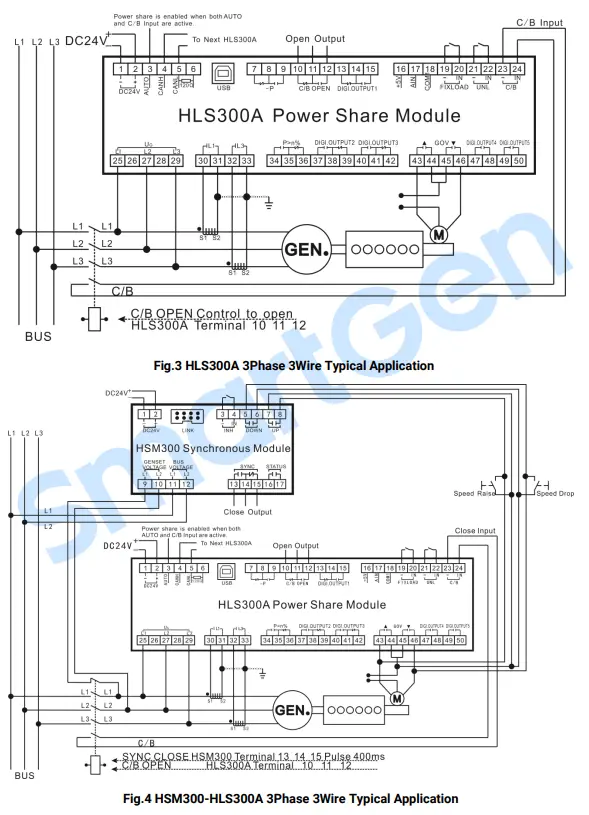
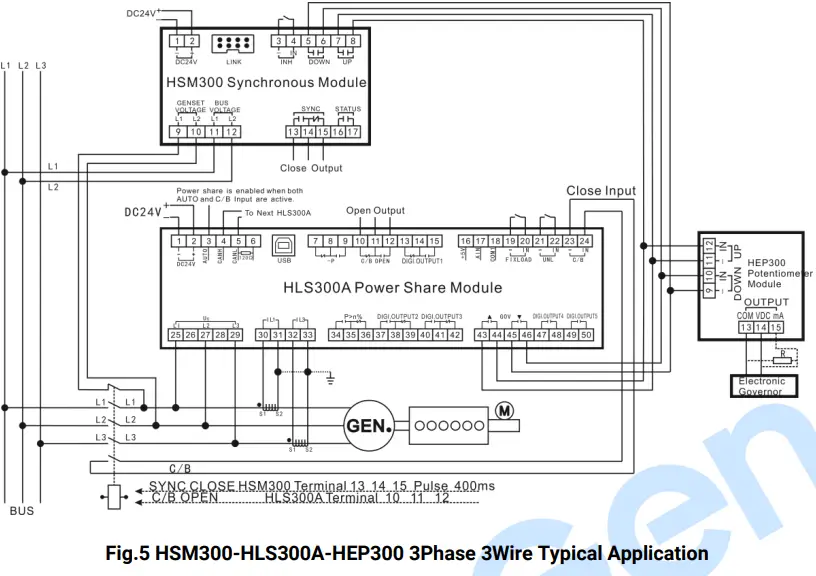
TYPICAL DIAGRAM

CASE DIMENSION
INSTALLATION PRECAUTIONS
OUTPUT AND EXPAND RELAYS
All outputs are relay contact output type. If it needs to expand the relays, please add freewheel diode to both ends of expand relay’s coils (when coils of relay have DC current) or, add resistance-capacitance return circuit (when coils of relay have AC current), in order to prevent disturbance for controller or other equipments.
AC INPUT
Current input must be connected to outside current transformer. And the current transformer’s secondary side current must be 5A. Meanwhile the phases of CT and input voltage must be correct, otherwise the sampling current and active power may be incorrect.
NOTE: When there is load current, transformer’s secondary side is prohibited to have open circuit.
WITHSTAND VOLTAGE TEST
CAUTION! When controller has been installed in control panel, if it needs doing the high voltage test, please disconnect all terminal connections, in order to prevent high voltage entering controller and damaging it.
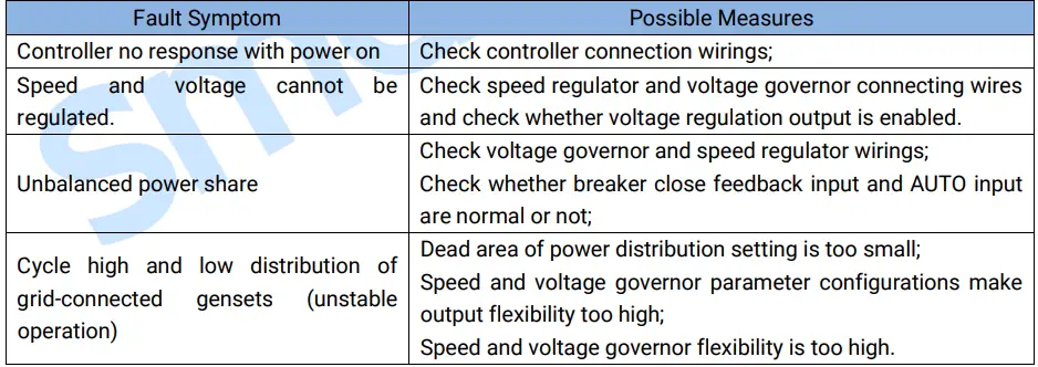
FAULT FINDING
The followings are the common faults and troubleshooting methods during the use process of our company controllers. If other unsolvable faults occur, please contact our company.
Table 9 Fault Finding