![]() HSM300 Synchronous Module
HSM300 Synchronous Module
User Manual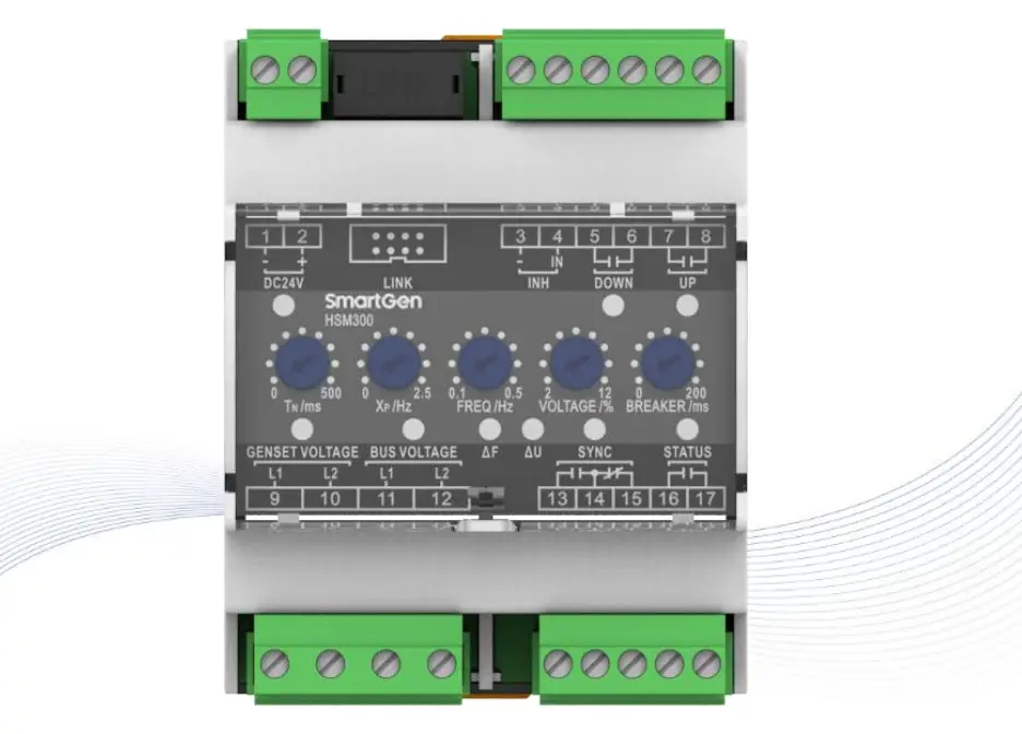
HSM300 Synchronous Module
All rights reserved. No part of this publication may be reproduced in any material form (including photocopying or storing in any medium by electronic means or other) without the written permission of the copyright holder.
Applications for the copyright holder’s written permission to reproduce any part of this publication should be addressed to SmartGen Technology at the address above.
Any reference to trademarked product names used within this publication is owned by their respective companies.
SmartGen Technology reserves the right to change the contents of this document without prior notice
Table 1 Software Version
| Date | Version | Content |
| 2015-05-21 | 1.0 | Original release. |
| 2017-03-09 | 1.1 | Add description of Raise/Drop Speed Relay Output Control; Modified parameters’ default values of Rated Voltage, Under Frequency and etc. |
| 2018-08-21 | 1.2 | “Widely power supply range DC(8-35)V, suitable to different starting battery voltage environment changed as “Widely power supply range DC(8-35)V” in section 2. |
| 2019-05-16 | 1.3 | Fixed wiring connection typical diagram. |
| 2022-09-16 | 1.4 | Updated company logo and manual format. |
Table 2 Symbol Description
| Sign | Instruction |
| Highlights an essential element of a procedure to ensure correctness. | |
| Indicates a procedure or practice, which, if not strictly observed, could result in damage or destruction of equipment. |
OVERVIEW
HSM300 Synchronous Module is specially designed for genset automatic parallel. On the basis of the parameters, the module automatically tests the conditions of paralleling (volt difference, frequency difference and phase) and sends parallel signal when the conditions meet parallel requirements. HSM300 Synchronous Module is used for the occasions that gens synchronize to bus. The module is brief to operate, easy to install and widely used for ship genset and land genset.
PERFORMANCE AND CHARACTERISTICS
- Suitable for 3-phase 4-wire, 3-phase 3-wire, 2-phase 3-wire, single phase 2-wire systems with frequency 50/60/Hz;
- Adjustable potentiometer allows for set main parameters of synchronizing;
- The operating parameters can be set via upper computer test software. LINK port should be connected to upper computer via SG72 module (USB to LINK);
- 4 relays output, 2 relays are used for UP output, DOWN output, 1 SYNC relay is used for sync close output, 1 STATUS relay is used for status output after close;
- 1 INH “inhibit sync close output” digital input, when the input is active and gens synchronize with bus, the SYNC indicator will illuminate and sync close relay is inhibited to output;
- Widely power supply range DC(8~35)V;
- 35mm guide rail mounting;
- Modular design, pluggable terminal, compact structure with easy installation.
SPECIFICATION
| Item | Content |
| Working Voltage | DC8.0V to 35.0V, continuous power supply. |
| Overall Consumption | slW (Standby modes0.5W) |
| AC Input | AC50V— AC620V (ph-ph) |
| AC Frequency | 50Hz/60Hz |
| SYNC Output | 7A AC250V Volts free output |
| UP Output | 5A AC250V/5A DC3OV Volts free output |
| DOWN Output | 5A AC250V/5A DC3OV Volts free output |
| STATUS Output | 5A AC250V/5A DC3OV Volts free output |
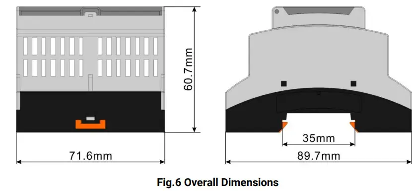
| Case Dimensions | 71.6mm x 89.7mm x 60.7mm |
| Working Temperature | (-25-1-70)°C |
| Working Humidity | (20-95)%RH |
| Storage Temperature | (-25-1-70)°C |
| Insulation Intensity | Apply AC2.2kV voltage between high voltage terminal and low voltage terminal; The leakage current is not more than 3mA within 1min. |
| Weight | 0.20kg |
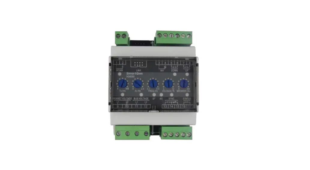
PANEL INDICATORS AND TERMINALS DESCRIPTION
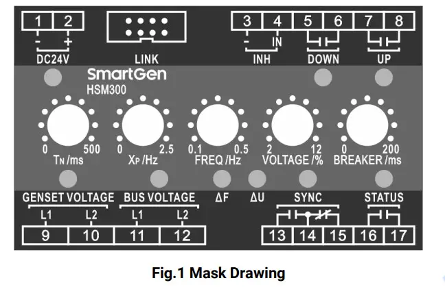
Table 4 LEDs Definition Description
| Indicators | Color | Description | Notes |
| DC 24V | Green | Power indicator, the lamp will illuminate when the power works well. | |
| UP | Green | When the raising speed pulse is sent, the lamp will illuminate. | |
| DOWN | Green | When the decreasing speed pulse is sent, the lamp will illuminate. | |
| GENSET | Green | When gens voltage and frequency normally, the lamp will illuminate; when gens voltage and frequency abnormally, the lamp will glitter; when there is no power, the lamp will extinguish. | |
| BUS | Green | When bus voltage and frequency normally, the lamp will illuminate; when bus voltage and frequency abnormally, the lamp will glitter; when there is no power, the lamp will extinguish. | |
| AF Freq. Diff. | Green | When gens and bus voltage, frequency normally, and real time frequency difference is within the setting limits, the lamp will illuminate. | |
| AU Volt Diff. | Green | When gens and bus voltage, frequency normally, and real time voltage difference is within the setting limits, the lamp will illuminate. | |
| SYNC Close | Red | When close relay outputs, the lamp will illuminate. Close pulse: 400ms. | |
| STATUS | Red | After close signal output, the relay output and the lamp will illuminate; when gens not synchronize with bus is detected, the relay will not output and the lamp will extinguish. |
Table 5 Potentiometer Description
| Potentiometer | Range | Description | Note |
| TN/ms control length of pulse | (25-500)ms | Control min. last time of pulse. | |
| Xp/Hz proportion range | (0-±2.5)Hz | In this area, pulse width and deviation value of rated frequency are in direct proportion. | Xp/Hz proportion range |
| FREQ/Hz | (0.1-0.5)Hz | Acceptable frequency difference. | |
| VOLTAGE/% | (2-12)% | Acceptable Voltage difference. | |
| BREAKER/ms | (20-200)ms | The time of switch close. |
Table 6 Terminal Description
| No. | Function | Cable | Note | ||
| 1. | DC 24V – | 2.5mm2 | Connected with negative of starter battery. | ||
| 2. | DC 24V + | 2.5mm2 | Connected with positive of starter battery. | ||
| 4. | INH | – | 1.0mm2 | “Close Output Inhibit” Input. | |
| IN | 1.0mm2 | ||||
| DOWN Output | 2.5mm2 | Output when speed reduces. | Normally open; Volts free output; 5A Rated. | ||
| 6. | |||||
| 7. | UP Output | 2.5mm2 | Output when speed raise. | Normally open; Volts free output; 5A Rated. | |
| 9. | GEN L1 | 1.0mm2 | Gen AC voltage input. | ||
| 10. | GEN L2 | ||||
| 11. | BUS L1 | 1.0mm2 | Bus AC voltage input. | ||
| 12. | BUS L2 | ||||
| 13. | SYNC | N/O | 2.5mm2 | Output when SYNC close. | Normally open/close; Volts free contact output; 7A Rated. |
| 14. | COM | ||||
| 15. | N/C | ||||
| 16. | STATUS | 2.5mm2 | Output when close. | Normally open, Volts free output; 5A Rated. | |
| 17. | 2.5mm2 | ||||
| LINK | Used for parameters setting or software upgrade. | ||||
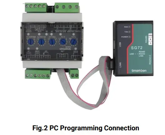
NOTE: Parameters setting and real-time monitoring can be implemented via LINK port by using PC software and an SG72 adapter which produced by our company.
SCOPES AND DEFINITIONS OF PROGRAMMABLE PARAMETERS
Table 7 Module Configurable Parameters
| No. | Items | Parameters | Defaults | Description |
| 1. | AC System | (0-3) | 0 | 0: 3P3W, 1: 1P2W, 2: 3P4W, 3: 2P3W |
| 2. | Rated Voltage | (30-30000) V | 400 | |
| 3. | PT Fitted | (0-1) | 0 | 0: Disabled 1: Enabled |
| 4. | PT Primary | (30-30000)V | 100 | |
| 5. | PT Secondary | (30-1000)V | 100 | |
| 6. | Over Volt | (0-1) | 1 | 0: Disabled 1: Enabled |
| 7. | (100-120)% | 115 | Threshold | |
| 8. | (100-120)% | 113 | Returned | |
| 9. | (0-3600)5 | 3 | Delay | |
| 10. | Under Volt | (0-1) | 1 | 0: Disabled 1: Enabled |
| 11. | (70-100)% | 82 | Threshold | |
| 12. | (70-100)% | 84 | Returned | |
| 13. | (0-3600)5 | 3 | Delay | |
| 14. | Over Frequency | (0-1) | 1 | 0: Disabled 1: Enabled |
| 15. | (100-120)% | 110 | Threshold | |
| 16. | (100-120)% | 104 | Returned | |
| 17. | (0-3600)s | 3 | Delay | |
| 18. | Under Frequency | (0-1) | 1 | 0: Disabled 1: Enabled |
| 19. | (80-100)% | 90 | Threshold | |
| 20. | (80-100)% | 96 | Returned | |
| 21. | (0-3600)s | 3 | Delay | |
| 22. | Bus AC System | (0-3) | 0 | 0: 3P3W, 1: 1P2W, 2: 3P4W, 3: 2P3W |
| 23. | Bus Rated Voltage | (30-30000)V | 400 | |
| 24. | Bus PT Fitted | (0-1) | 0 | 0: Disabled 1: Enabled |
| 25. | Bus PT Primary | (30-30000)V | 100 | |
| 26. | Bus PT Secondary | (30-1000)V | 100 | |
| 27. | Bus Over Voltage | (0-1) | 1 | 0: Disabled 1: Enabled |
| 28. | (100-120)% | 115 | Threshold | |
| 29. | (100-120)% | 113 | Returned | |
| 30. | (0-3600)s | 3 | Delay | |
| 31. | Bus Under Voltage | (0-1) | 1 | 0: Disabled 1: Enabled |
| 32. | (70-100)% | 82 | Threshold | |
| 33. | (70-100)% | 84 | Returned | |
| 34. | (0-3600)s | 3 | Delay | |
| 35. | Bus Over Frequency | (0-1) | 1 | 0: Disabled 1: Enabled |
| 36. | (100-120)% | 110 | Threshold |
| No. | Items | Parameters | Defaults | Description |
| 37. | (100-120)% | 104 | Returned | |
| 38. | (0-3600)s | 3 | Delay | |
| 39. | Bus Under Frequency | (0-1) | 1 | 0: Disabled 1: Enabled |
| 40. | (80-100)% | 90 | Threshold | |
| 41. | (80-100)% | 96 | Returned | |
| 42. | (0-3600)s | 3 | Delay | |
| 43. | Address | (1-254) | 1 | |
| 44. | Tp | (1-20) | 10 | Speed regular pulse period=ToxIN |
FUNCTION DESCRIPTION
HSM300 Synchronous Module is to synchronize generator to bus. When voltage difference, frequency difference and phase difference are within pre-set value, it will send synchronization signal to close gens switch. Because its switch close response time can be set, the module can be used for gensets of various source powers.
Thresholds of over voltage, under voltage, over frequency and under frequency of gens and bus can be set via monitoring software of PC. When the module detects voltage and frequency of gens and bus are normal, it will begin to adjust speed. When pressure difference, frequency difference and phase difference are within pre-set value, it will send synchronize signal to close gens switch.
RAISE/DROP SPEED RELAY OUTPUT CONTROL
When deviation area XP is set as 2Hz, the working principle of raise/drop speed relay is as follows. 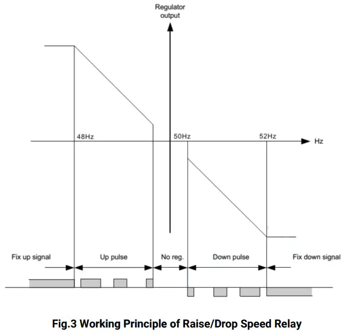
Table 8 Five Steps for Relay Output Regulation Function
| No. | Range | Description | Note |
| 1 | Fix Up Signal | Continuously raise signal | Activation adjusting. Since too large adjust error, ascending frequency relay will continuously be activated. |
| 2 | Up Pulse | Raise the pulse | System activates regulatory function, then ascending frequency relay will eliminate deviation in the pulse way. |
| 3 | No Reg. | No regulation | No regulation in this area. |
| 4 | Down pulse | Drop down the pulse | System activates regulatory function, descending frequency relay will eliminate deviation in the pulse way. |
| 5 | Fix down signal | Continuously drop down signal | System activates regulatory function, descending frequency relay will continuously be activated. |
As showing in fig.3, when adjusting deviation XP exceeds pre-set value, the relay will be in the continuous activate status; when XP is not large, the relay will work in pulse way, and the pulse will become shorter along with the deviation became smaller. When regulator output value is close to “No Reg.”, pulse width will be the shortest value; when regulator output value is nearest to the “Down Pulse”, pulse width will be the longest value.
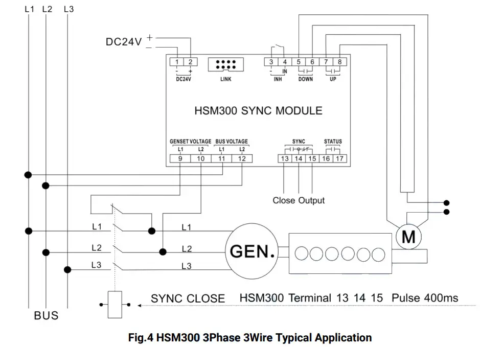
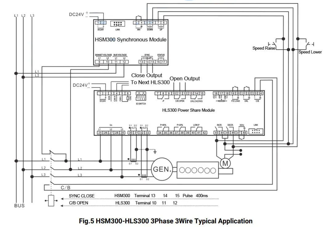
TYPICAL APPLICATION DIAGRAM
CASE DIMENSION
INSTALLATION NOTES
10.1 OUTPUT AND EXPAND RELAYS
All outputs are relay contact output type. If need to expand the relays, please add freewheel diode to both ends of expand relay’s coils (when coils of relay have DC current) or add resistance-capacitance return circuit (when coils of relay have AC current), in order to prevent disturbance to controller or others equipment.
10.2 WITHSTAND VOLTAGE TEST
CAUTION! When relay had been installed in control panel, if need the high voltage test, please disconnect relay’s all terminal connections, in order to prevent high voltage into relay and damage it.


