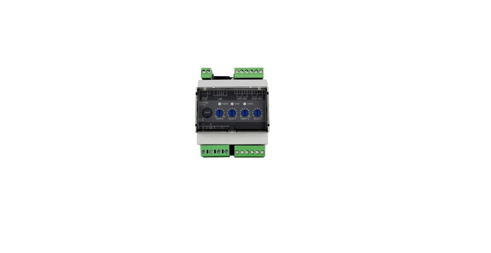
SmartGen HOC300 Over Current Protection Relay Multifunctional Protection Module

Table 1 Version History
| Date | Version | Content |
| 2014-08-07 | 1.0 | Original release. |
| 2014-10-09 | 1.1 | Rename the product. |
| 2015-03-24 | 1.2 | Add “Multifunctional Protection Module” to the name |
| 2021-09-29 | 1.3 |
Table 2 Symbol Instruction
| Symbol | Instruction |
| NOTE | Highlights an essential element of a procedure to ensure correctness. |
| CAUTION | Indicates a procedure or practice, which, if not strictly observed, could result in damage or destruction of equipment. |
OVERVIEW
HOC300 over the current protection relay is widely used in marine Genset fields and land genset fields. HOC300 over current protection relay detects load current accurately. Over-current trip or pre-trip relay outputs and alarm protection activates when the load current has exceeded the set value.
PERFORMANCE AND CHARACTERISTICS
- Suitable for 3 phase 4 wire, 3 phase 3 wire, single phase 2 wire, an d 2 phase 3 wire systems with frequency 50/60/400Hz;
- Detects load current accurately.
- Adjustable potentiometer allows for set value adjusting and delay value setting.
- relay output
- One test button, test the over current trip/pre trip relay and indicator.
- W idely power supply range DC(8~35)V, suitable to different starting battery voltage environment;
- 35mm guide rail mounting.
- Modular design, pluggable terminal, compact structure with easy installation
TECHNICAL PARAMETERS
Table 3 Technical Parameters
| Parameter | Details |
| Working Voltage | DC8. 0V to 35. 0V, continuous power supply |
| Overall Consumption | <0.9W (Standby mode: ≤0.28W) |
| Pre-Trip Relay Output | 5A AC250V Volts free output |
| Trip Relay Output | 5A AC250V Volts free output |
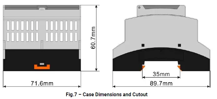
| Case Dimensions | 89.7mm x 71.6mm x 60.7mm |
| CT Secondary Current | Rated 5A |
| Working Conditions | Temperature: (-25~+70)°C Humidity: (20~93)%RH |
| Storage Conditions | Temperature:(-25~+70)°C |
| Insulation Intensity | Apply AC2.2kV voltage between high voltage terminal and low voltage terminal; The leakage current is not more than 3mA within 1min. |
| Weight | 0.24kg |
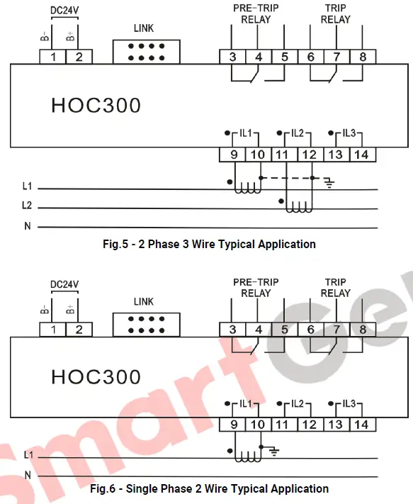
PANEL TERMINAL DESCRIPTION
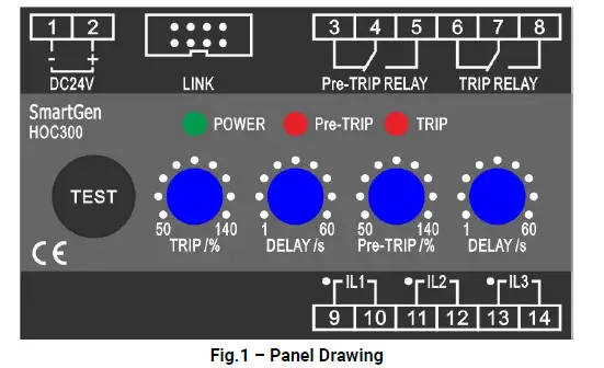
Table 4 Description of Terminal Connection
| NO. | Functions | Cable Size | Remark | ||
| 1 | B- | 1.0mm2 | Connected with negative of starter battery. | ||
| 2 | B+ | 1.0mm2 | Connected with positive of starter battery. | ||
| 3 |
Pre-TRIP RELAY | Normally Open |
2.5 mm2 | Active when the load current has exceeded the set value and the delay timer has expired while deactivate when the load current returns to normal. |
Normally open; Volts free output; 5A Rated |
| 4 | COM | ||||
| 5 | Normally Open | ||||
| 6 |
TRIP RELAY | Normally Close |
2.5 mm2 | Active when the load current has exceeded the set value and the delay timer has expired while deactivate when the load current returns to normal. | |
| 7 | COM | ||||
| 8 | Normally Open | ||||
| 9 | IL1 | Dotted Terminals | 1.5 mm2 | CT A-phase input; Externally connected to secondary coil of current transformer (rated 5A). | |
| 10 | |||||
| 11 | IL2 | Dotted Terminals | 1.5 mm2 | CT B-phase input; Externally connected to secondary coil of current transformer (rated 5A). | |
| 12 | |||||
| 13 | IL3 | Dotted Terminals | 1.5 mm2 | CT C-phase input; Externally connected to secondary coil of current transformer (rated 5A). | |
| 14 | |||||
| LINK Port | Used for parameters setting. | ||||
FUNCTION DESCRIPTION
Table 5 Function Description
| Item | Description |
| Power Indicator | Power supply indicator; It is illuminated when the relay is powered up. (green light) |
| Pre-Trip Indicator | It flashes once per second when the load current has exceeded the set value and Pre-TRIP indicator light on when the delay timer has expired. The indicator extinguished after current returns to normal. (red light) |
| Trip Indicator | It flashes once per second when the load current has exceeded the set value and TRIP indicator light on when the delay timer has expired. The indicator extinguished after current returns to normal. (red light) |
| TEST Button | Press the button for 3 seconds and enter the Test Mode. The Pre-Trip relay and Pre-Trip indicator output; Release and press the button again, the over curren trip relay and indicator output. Press the button a third time to exit the Test Mode. Exit the Test Mode after 30s without any operation. |
| TRIP /% Over Currrent Trip Set Value | Used for adjusting over current set value. Range: (50~140)%; Setting value is the percentage of rated current value(5A). |
| DELAY /s Delay Value Potentiometer | Used for adjusting over current action delay value. Range: (1~60)s |
| Pre-TRIP /% Pre-Trip Set Value | Used for adjusting pre-trip set value. Range: (50~140)%; Setting value is the percentage of rated current value(5A). |
| DELAY /s Delay Value Potentiometer | Used for adjusting delay value. Range: (1~60)s |
SCOPES AND DEFINITIONS OF PROGRAMMABLE PARAMETERS
Table 6 Programmable Parameters
| No. | Items | Parameters | Defaults | Description |
| 1 | AC System | (0-3) | 0 | 0: 3P4W, 1: 3P3W 2: 2P3W, 3:1P2W |
| 2 | CT Ratio | (5-6000)/5 | 500 | |
| 3 | Full Load Rated Current | (5-6000)A | 500 | |
| 4 | Communication Address | (1-254) | 1 |
PC Program:
Parameters setting and real time monitoring can be implemented via LINK port by using PC software and an SG72 adapter which produced by our company. As follows: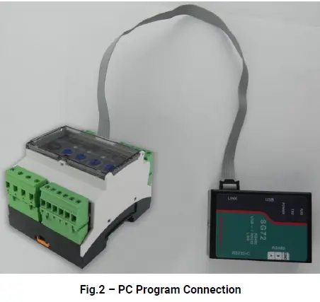
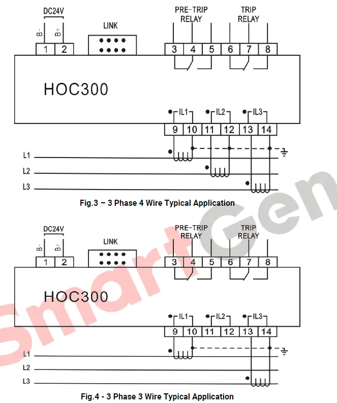
TYPICAL DIAGRAM
INSTALLATION DIMENSIONS
Output And Expand Relay s
All outputs are relay contact output type. If need to expand the relays, please add a freewheel diode to both ends of expanding relay’s coils (when the coils of the relay has DC current) or, add a resistance-capacitance return circuit (when coils of the relay has AC current), in order to prevent disturbance to controller or others equipment
AC Input
Current input must be connected to the outside current transformer. And the current transformer’s secondary side current must be 5A.
Note: When there is a load current, the transformer’s secondary side prohibits an open circuit.
3) Withstand Voltage Test
CAUTION!
When the relay had been installed in the control panel, if need the high-voltage test, please disconnect the relay’s all terminal connections, in order to prevent high voltage into the relay and damaging it.
Smarten Technology Co., Ltd
No.28 Jinsuo Road, Zhengzhou, Henan Province, China
Tel: +86-371-67988888/67981888/67992951 +86-371-67981000(overseas)
Fax: +86-371-67992952
Email: [email protected]
Web:
www.smartgen.com.cn
www.smartgen.cn
All rights reserved. No part of this publication may be reproduced in any material form (including photocopying or storing in any medium by electronic means or other) without the written permission of the copyright holder. Smarten Technology reserves the right to change the contents of this document without prior notice.


