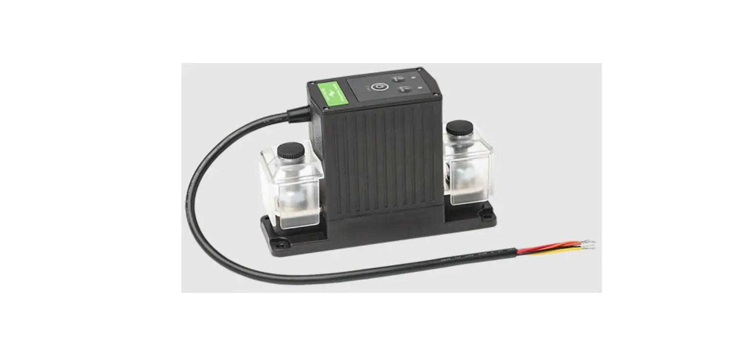

tbs electronics DC Modular 500A Baery Protect Relay TBP
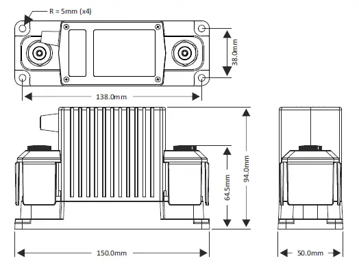
Dimensions
Precautions
- Please install this product in a dry indoor location, as close as possible to the battery. To be installed only by qualified technicians.
- To avoid fire hazards, use correctly sized cables which are suitable to carry the expected load currents in your application. The maximum continuous TBP current rating of 500A is only valid when a total cable size of at least 200mm² is connected to the M10 studs. Or when the TBP is part of a DC Modular system containing large busbars and fuseholders.
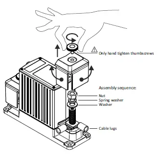
- To avoid fire hazards or damaging the TBP, please make sure that spring- and flat washers are always placed directly below the nut. Never place washers between: busbar and cable lug, multiple cable lugs on the same stud, busbar and linkplate or cable lug and linkplate.
- To avoid fire hazards or damaging the TBP, please make sure that all nuts are securely ghtened.
- Please apply our recommended torque rating of 22Nm for the M10 nuts.
- Please make sure that all connection cables are properly strain relieved, to avoid excessivemechanical stress on the TBP.
Removing stud covers for cable connection access
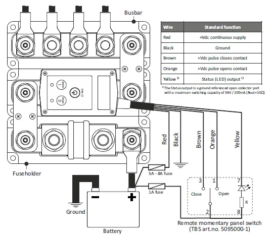
Wiring example
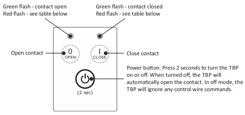
General operation
Red Flash Table
| Opera ng mode | LED flash behavior |
| Error (see error table) | Both red LEDs flash at the same me |
| Low voltage disconnect | Red LEDs flash alternately (slow) |
| Override mode | Red LEDs flash alternately (fast) |
Error table:
| Cause | Remedy |
| Supply voltage too low | Increase supply voltage |
| Supply voltage too high | Decrease supply voltage |
| TBP temperature too high | Reduce the contact current, check all cable connec ons |
| Contacts are welded | Replace the TBP |
During normal operation a green flashing LED indicates whether the TBP contact is open or closed. This contact state can be changed by pressing the local OPEN and CLOSE buttons, or through the remote control wires.
If the TBP is configured with an enabled disconnect voltage, the contact will automatically open after 1 minute when the battery voltage has dropped below the disconnect voltage level. In this mode, the two TBP LEDs will flash red alternately. If a reconnect voltage has been set as well, the contact will close automatically when the battery voltage exceeds the reconnect voltage value again.
If no disconnect or reconnect voltages are programmed inside the TBP, it will just operate as a manually operated remote battery switch and there is no automatic control based on battery voltage anymore.
TBS Panel Switch indicator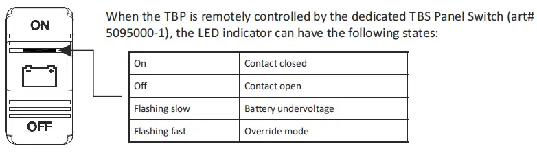
Override mode
In situations where the TBP has opened the contact due to a battery undervoltage, it can be handy to temporarily close the contact in case of an emergency or when it is needed to connect the battery to a charging source like an inverter/charger combination. For these situations we have implemented the Override mode. When this mode is activated, the contact closes for 1 minute. When during this 1 minute the battery voltage rises above the disconnect voltage (due to a connected charging source), the contact remains closed and the TBP will automatically operate in the normal mode again. When after this 1 minute the battery voltage remains below the disconnect voltage, the contact will open again.
Override mode is only available for remote control in control modes 1, 2, 3, 6 and 7 (see control mode table in the Change remote control mode chapter). It can be locally activated in any control mode by pressing the ‘I’ (Close) button for 2 seconds after the TBP contact has opened due to a battery undervoltage. In 2-wire control modes 1, 2 or 3 it can also be activated remotely by pressing the ‘ON’ position of the TBS Panel Switch for 2 seconds. When operating in single wire control modes 6 or 7, Override mode can be activated by shortly pushing the remote SPST switch from OFF to ON again. While operating in Override mode, the local LEDs will flash red alternately (fast) and the TBS Panel Switch LED will flash fast as well. \
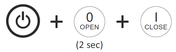
Change remote control mode
When in off mode, press all three buttons simultaneously for two seconds to enter the setup mode:
Step through the control modes by pressing the OPEN (up) or CLOSE (down) buttons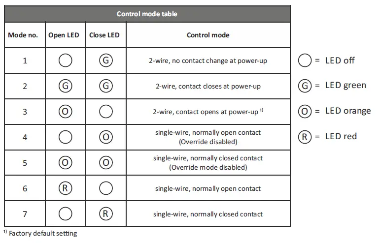
When the desired control mode is selected, press the Power button for 2 seconds to save the settng. Press the Power button again for 2 seconds to activate the TBP with the new control mode. Settngs remain saved if the supply voltage is lost.
Additional control mode explanations: Modes 1, 2 & 3: +Vdc pulse on brown wire to close, +Vdc pulse on orange wire to open.
Modes 4 & 6: + Vdc continuous on brown wire to close, 0Vdc on brown wire to open. Orange wire not used.
Modes 5 & 7: Vdc continuous on brown wire to open, 0Vdc on brown wire to close. Orange wire not used.
Change disconnect and reconnect voltage levels
When in off mode, press the two buttons indicated below simultaneously for 2 seconds to enter the desired setup mode: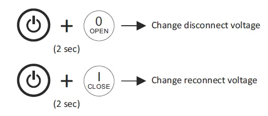
Step through all voltage level settngs by pressing the OPEN (up) or CLOSE (down) buttons
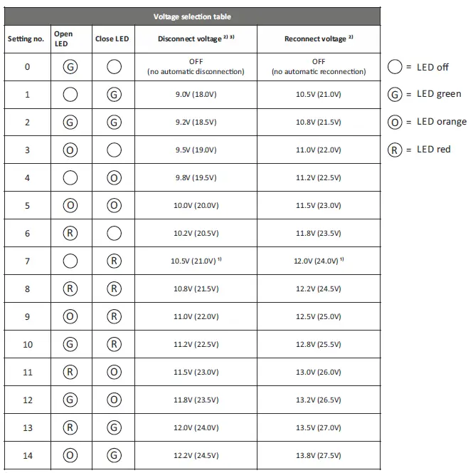
- Factory default settng
- Voltage value between brackets is for 24V version
- Contact opens after 1 minute when the battery voltage drops below the selected disconnect voltage. When within this time period the battery voltage drops more than 1V below the selected disconnect voltage, the contact opens after 2 seconds.
- When the desired disconnect or reconnect voltage is selected, press the Power button for 2 seconds to save the seting. Press the Power button again for 2 seconds to activate the TBP with the new disconnect and/or reconnect voltage settngs. Settngs remain saved if the supply voltage is lost.
Features
- Smart high current magnetic latching relay, draws virtually no current in On (Close) or Off (Open) state.
- Silver alloy contacts and silver plated copper busbars, for maximum conductivity and high reliability when switching live loads.
- Local Open and Close buttons on top, to manually override the switch state.
- Automatic load disconnection (10 programmable disconnect- and reconnect voltage levels)
- Override mode allows temporary battery connection during under voltage conditions, in case of emergency or to facilitate the battery charging process.
- 5 wire interface cable for remote control by panel switch, battery monitor or BMS. Compatible with two wire or single wire On/Off control. Includes status wire for controlling indicator light or providing feedback to BMS.
- Stainless steel studs, washers and nuts for optimal corrosion resistance.
- Unique grid optimized footprint allows space saving arrangements with other DC Modular products.
- Special fiber reinforced plastic housing offers excellent high temperature properties, good chemical resistance and high strength.
- Robust transparent covers with breakouts to allow wire access from any direction.
- Smart terminal design allows dual mirrored cable lug connections.
Specifications
| Parameter | TBP-12-500 (art# 5074410) | TBP-24-500 (art# 5074420) |
| Contact circuit (electrical) | ||
| Maximum voltage | 60Vdc | |
| Nominal current @ 25°C | 500A (see Precau on #2) | |
| Cranking current (1 minute) | 1000A | |
| Nominal make / break current | 500A (0 .. 34Vdc) 350A (35 .. 60Vdc) | |
| Peak make / break current | 1600A (0 .. 34Vdc) 1200A (35 .. 60Vdc) | |
| Control circuit (electrical) | ||
| Coil / supply voltage (+Vdc) | 7 .. 17Vdc | 14 .. 34Vdc |
| Coil / supply current (idle state) | < 100μA | |
| Coil / supply current (state change) | < 4A | < 3A |
| ControlRwBireSsuspppley ccuirfirecnat ons | < 3mA (when ac ve) | |
| General | ||
| Remote control ¹⁾ | By control wires (length 40cm, max. 15m) | |
| Local control | On/Standby, Open and Close contact, Override mode | |
| Automa c disconnect and reconnect | Yes (10 individually programmable disconnect and reconnect voltage levels) | |
| Indicators | Contact open/close, Undervoltage disconnect, Override mode, Error and Setup | |
| Protected against | High temperature, High/Low supply voltage, Igni on (ISO 8846) | |
| Mechanical life | 100000 cycles | |
| Electrical life | 10000 cycles (@ 400A/24V/resis ve) | |
| Opera ng temperature range | -20 .. +60°C | |
| Connec on studs / DCM grid size | M10 / 1 x 3 | |
| Protec on class / weight | IP 65 / 800 grams | |
| Standards | EMC: 2014/30/EU & UNECE Regula on 10, Low voltage Direc ve: 2014/35/EU, RoHS: 2011/65/EU, ISO 8846 | |


