TBS Electronics DC Modular 500A Battry Protect Relay Owner’s Manual
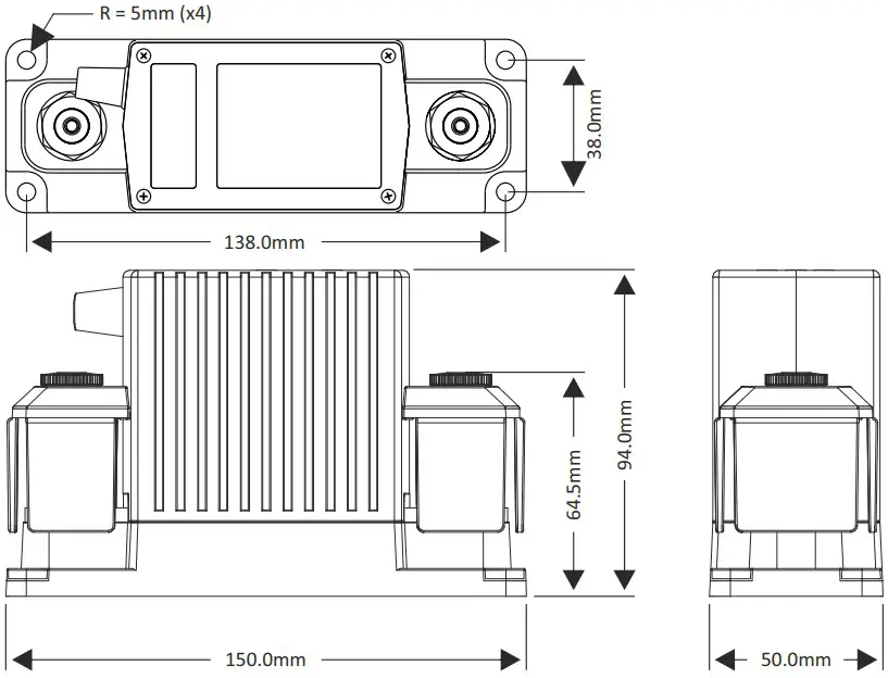
Dimensions
Precautions
- Please install this product in a dry indoor locaon, as close as possible to the baery. To be installed only by qualified technicians.
- To avoid fire hazards, use correctly sized cables which are suitable to carry the expected load currents in your applicaon. The maximum connuous TBP current rang of 500A is only valid when a total cable size of at least 200mm² is connected to the M10 studs. Or when the TBP is part of a DC Modular system containing large busbars and fuseholders.
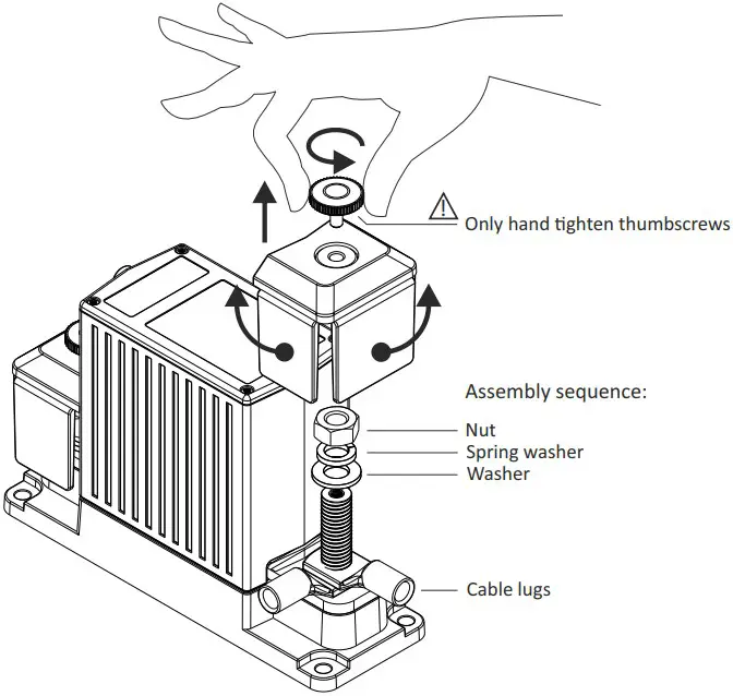
- To avoid fire hazards or damaging the TBP, please make sure that all nuts are securely ghtened.
Please apply our recommended torque rang of 22Nm for the M10 nuts. - To avoid fire hazards or damaging the TBP, please make sure that spring- and flat washers are always placed directly below the nut. Never place washers between: busbar and cable lug, mulple cable lugs on the same stud, busbar and linkplate or cable lug and linkplate.
- Please make sure that all connecon cables are properly strain relieved, to avoid excessive mechanical stress on the TBP.
Removing stud covers for cable connecon access
Wiring example
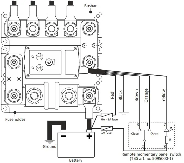
| Wire | Standard function |
| Red | +Vdc continuous supply |
| Black | Ground |
| Orange | +Vdc pulse closes contact |
| Yellow ¹⁾ | Status (LED) output ¹ |
The Status output is a ground referenced open collector port with a maximum switching capacity of 34V / 100mA (Rout≈10Ω
General operation
| Red LED flash table | ||||
| Both LEDs flashing red (error) | OPEN LED flashing red (error) | CLOSE LED flashing red (error) | Red LEDs flash alternately (slow) | Red LEDs flash alternately (fast) |
| Supply voltage too low–Supply voltage too high–TBP Temperature too high–Contacts are welded, replace TBP | Low voltage disconnect, contact remains open after voltage recovery-Contact fails to open. Check if supply voltage is within range. Otherwise return TBP for service | Contact fails to close. Check if supply voltage is within range. Otherwise return TBP for service. | Low voltage disconnect, contact closes automatically after voltage recovery | Override mode |
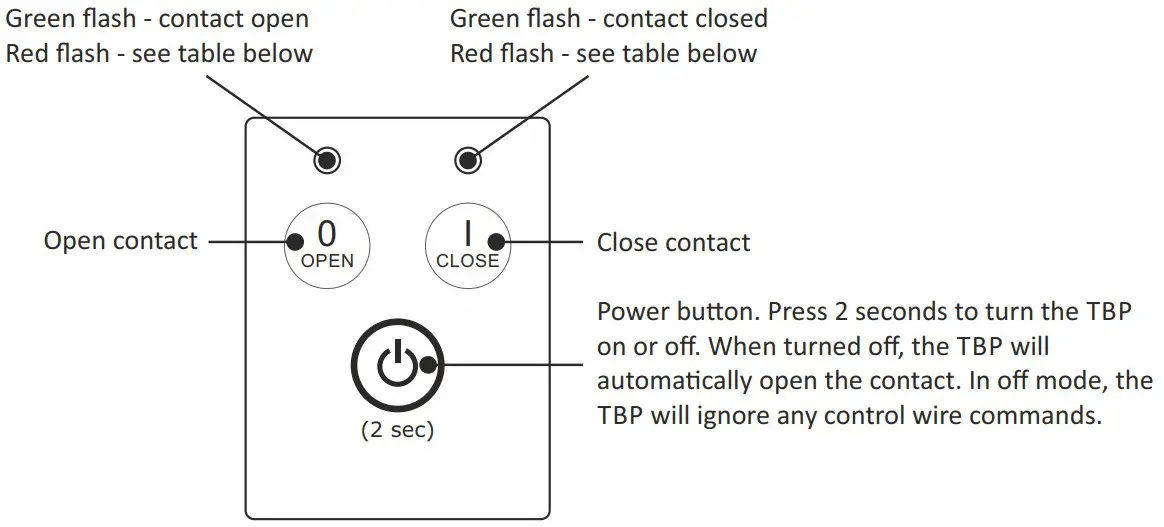
During normal operaon a green flashing LED indicates whether the TBP contact is open or closed. This contact state can be changed by pressing the local OPEN and CLOSE buons, or through the remote control wires.
If the TBP is configured with an enabled disconnect voltage, the contact will automacally open aer 1 minute when the baery voltage has dropped below the disconnect voltage level. In this mode, the two TBP LEDs will flash red alternately. If a reconnect voltage has been set as well, the contact will close automacally when the baery voltage exceeds the reconnect voltage value again.
If no disconnect or reconnect voltages are programmed inside the TBP, it will just operate as a manually operated remote baery switch and there is no automac control based on baery voltage anymore.
TBS Panel Switch indicator
When the TBP is remotely controlled by the dedicated TBS Panel Switch (art# 5095000-1), the LED indicator can have the following states: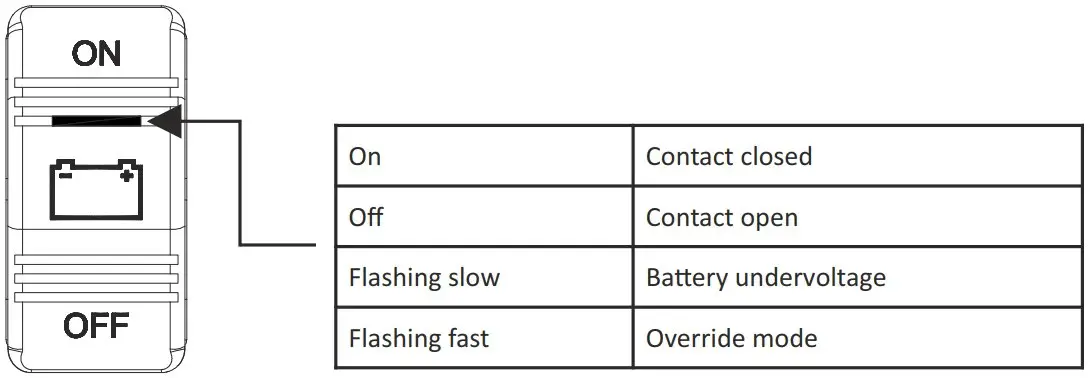
Override mode
In situaons where the TBP has opened the contact due to a baery undervoltage, it can be handy to temporarily close the contact in case of an emergency or when it is needed to connect the baery to a charging source like an inverter/charger combinaon. For these situaons we have implemented the Override mode. When this mode is acvated, the contact closes for 1 minute. When during this 1 minute the baery voltage rises above the disconnect voltage (due to a connected charging source), the contact remains closed and the TBP will automacally operate in the normal mode again. When aer this 1 minute the baery voltage remains below the disconnect voltage, the contact will open again.
Override mode is only available for remote control in control modes 1, 2, 3, 6 and 7 (see control mode table in the Change remote control mode chapter). It can be locally acvated in any control mode by pressing the ‘I’ (Close) buon for 2 seconds aer the TBP contact has opened due to a baery undervoltage. In 2-wire control modes 1, 2 or 3 it can also be acvated remotely by pressing the ‘ON’ posion of the TBS Panel Switch for 2 seconds. When operang in single wire control modes 6 or 7, Override mode can be acvated by shortly pushing the remote SPST switch from OFF to ON again. While operang in Override mode, the local LEDs will flash red alternately (fast) and the TBS Panel Switch LED will flash fast as well.
Change remote control mode
When in off mode, press all three buons simultaneously for two seconds to enter the setup mode: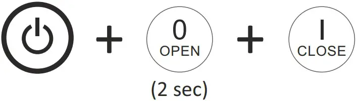
Step through the control modes by pressing the OPEN (up) or CLOSE (down) buttons
| Control mode table | |||
| Mode no. | Open LED | Close LED | Control mode |
| 1 | 2-wire, no contact change at power-up | ||
| 2 | 2-wire, contact closes at power-up | ||
| 3 | 2-wire, contact opens at power-up ¹⁾ | ||
| 4 | single-wire, normally open contact (Override disabled) | ||
| 5 | single-wire, normally closed contact (Override mode disabled) | ||
| 6 | single-wire, normally open contact | ||
| 7 | single-wire, normally closed contact | ||
![]() = LED off
= LED off![]() = LED green
= LED green![]() LED orange
LED orange![]() = LED red
= LED red
When the desired control mode is selected, press the Power buon for 2 seconds to save the seng.
Press the Power buon again for 2 seconds to acvate the TBP with the new control mode. Sengs remain saved if the supply voltage is lost
Addional control mode explanaons:
Modes 1, 2 & 3: +Vdc pulse on brown wire to close, +Vdc pulse on orange wire to open.
Modes 4 & 6: +Vdc connuous on brown wire to close, 0Vdc on brown wire to open. Orange wire not used.
Modes 5 & 7: +Vdc connuous on brown wire to open, 0Vdc on brown wire to close. Orange wire not used.
Change disconnect and reconnect voltage levels
When in off mode, press the two buons indicated below simultaneously for 2 seconds to enter the desired setup mode: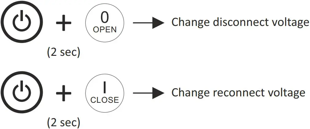
Step through all voltage level sengs by pressing the OPEN (up) or CLOSE (down) buons
| Voltage selection table | ||||
| SeEng no. | Open LED | Close LED | Disconnect voltage ²⁾ ³⁾ | Reconnect voltage ²⁾ |
| 0 | OFF (no automatic disconnection) | OFF (no automatic reconnection) | ||
| 1 | 9.0V (18.0V) | 10.5V (21.0V) | ||
| 2 | 9.2V (18.5V) | 10.8V (21.5V) | ||
| 3 | 9.5V (19.0V) | 11.0V (22.0V) | ||
| 4 | 9.8V (19.5V) | 11.2V (22.5V) | ||
| 5 | 10.0V (20.0V) | 11.5V (23.0V) | ||
| 6 | 10.2V (20.5V) | 11.8V (23.5V) | ||
| 7 | 10.5V (21.0V) ¹⁾ | 12.0V (24.0V) ¹⁾ | ||
| 8 | 10.8V (21.5V) | 12.2V (24.5V) | ||
| 9 | 11.0V (22.0V) | 12.5V (25.0V) | ||
| 10 | 11.2V (22.5V) | 12.8V (25.5V) | ||
| 11 | 11.5V (23.0V) | 13.0V (26.0V) | ||
| 12 | 11.8V (23.5V) | 13.2V (26.5V) | ||
| 13 | 12.0V (24.0V) | 13.5V (27.0V) | ||
| 14 | 12.2V (24.5V) | 13.8V (27.5V) | ||
- Factory default setting.
- Voltage value between brackets is for 24V version
- Contact opens aer 1 minute when the baery voltage drops below the selected disconnect voltage. When within this me period the baery voltage drops more than 1V (2V) below the selected disconnect voltage, the contact opens aer 2 seconds.
When the desired disconnect or reconnect voltage is selected, press the Power buon for 2 seconds to save the seng. Press the Power buon again for 2 seconds to acvate the TBP with the new disconnect and/or reconnect voltage sengs. Sengs remain saved if the supply voltage is lost.
Features
- Smart high current magnec latching relay, draws virtually no current in On (Close) or Off (Open) state.
- Silver alloy contacts and silver plated copper busbars, for maximum conducvity and high reliability when switching live loads.
- Local Open and Close buons on top, to manually override the switch state.
- Automac load disconnecon (10 programmable disconnect- and reconnect voltage levels)
- Override mode allows temporary baery connecon during under voltage condions, in case of emergency or to facilitate the baery charging process.
- 5 wire interface cable for remote control by panel switch, baery monitor or BMS. Compable with two wire or single wire On/Off control. Includes status wire for controlling indicator light or providing feedback to BMS.
- Stainless steel studs, washers and nuts for opmal corrosion resistance.
- Unique grid opmized footprint allows space saving arrangements with other DC Modular products.
- Special fiber reinforced plasc housing offers excellent high temperature properes, good chemical resistance and high strength.
- Robust transparent covers with breakouts to allow wire access from any direcon.
Smart terminal design allows dual mirrored cable lug connecons.
Specifications
| Parameter | TBP-12-500 (art# 5074410) | TBP-24-500 (art# 5074420) |
| Contact circuit (electrical) | ||
| Maximum voltage | 60Vdc | |
| Nominal current @ 25°C | 500A (see Precaution #2) | |
| Cranking current (1 minute) | 1000A | |
| Nominal make / break current | 500A (0 .. 34Vdc)350A (35 .. 60Vdc) | |
| Peak make / break current ¹⁾ | 1600A (0 .. 34Vdc)1200A (35 .. 60Vdc) | |
| Control circuit (electrical) | ||
| Coil / supply voltage (+Vdc) | 7.5 .. 17Vdc | 15 .. 34Vdc |
| Coil / supply current (idle state) | < 100μA | |
| Coil / supply current (state change) | < 6A | < 3A |
| Control wire supply current | < 3mA (when active) | |
| Control wire threshold voltage | > 5Vdc | |
| General | ||
| Remote control ²⁾ | By control wires (length 40cm, max. 15m) | |
| Local control | On/Standby, Open and Close contact, Override mode | |
| Automatic disconnect and reconnect | Yes (10 individually programmable disconnect and reconnect voltage levels) | |
| Indicators | Contact open/close, Undervoltage disconnect, Override mode, Error and Setup | |
| Protected against | High temperature, High/Low supply voltage, Ignition (ISO 8846) | |
| Mechanical life | 100000 cycles | |
| Electrical life | 10000 cycles (@ 400A/24V/resistive) | |
| Operating temperature range | -20 .. +60°C | |
| Connection studs / DCM grid size | M10 / 1 x 3 | |
| Protection class / weight | IP 65 / 800 grams | |
| Standards | EMC: 2014/30/EU & UNECE Regulation 10, Low voltage Directive: 2014/35/EU, RoHS: 2011/65/EU, ISO 8846 | |
Note : the given specificaons are subject to change without noce
- When switching in the upper voltage range, it is advised to install a proper pre charge circuit to keep the peak make current significantly below this value
- Panel switch with LED indicator oponally available (Art. no. 5095000-1)
TBS Electronics BV
De Marowijne 3
1689AR Zwaag
The Netherlands
www.tbs-electronics.com