tbs electronics EN 500A DCM Remote Battery Switch Instruction Manual
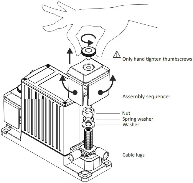
Main cable installation
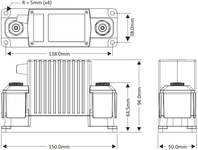
Dimensions
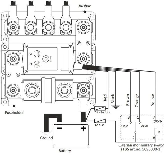
Wiring example
Wire table
| Wire | Standard funcon |
| Red | +Vdc continuous supply |
| Black | Ground |
| Brown | +Vdc pulse closes contact |
| Orange | +Vdc pulse opens contact |
| Yellow | Status (LED) output |
The Status output is a ground referenced open collector port with a maximum switching capacity of 34V / 100mA (Rout ≈ 10 Ω)
De Status uitgang is een aan massa gerefereerde open collector poort met een maximale schakelcapaciteit van 34V / 100mA (Ruit ≈ 10 Ω)
Error table
| Error table | ||
| Both LEDs flashing red | OPEN LED flashing red | CLOSE LED flashing red |
| Supply voltage too lowSupply voltage too highRBS Temperature too highContacts are welded, replace RBS | Contact fails to open. Check if supply voltage is within range. Otherwise return RBS for service. | Contact fails to close. Check if supply voltage is within range. Otherwise return RBS for service. |
Change control mode
When in off mode, press all three buons simultaneously for three seconds to enter the setup mode: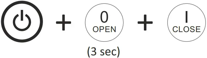
Step through the control modes by pressing the OPEN (up) or CLOSE (down) buons
| Control mode table | |||
| Mode no. | Open LED | Close LED | Control mode |
| 1 | 2-wire, no contact change at power-up | ||
| 2 | 2-wire, contact closes at power-up | ||
| 3 | O | 2-wire, contact opens at power-up | |
| 4 | single-wire, normally open contact | ||
| 5 | single-wire, normally closed contact | ||
![]() LED off
LED off![]() LED green
LED green![]() LED orange
LED orange
When the desired control mode is selected, press the Power buon for 2 seconds to save the seng.
Press the Power buon again for 2 seconds to acvate the RBS with the new control mode.
Modes 1, 2 & 3: +Vdc pulse on brown wire to close, +Vdc pulse on orange wire to open.
Mode 4: +Vdc connuous on brown wire to close, 0Vdc on brown wire to open. Orange wire not used
Mode 5: +Vdc connuous on brown wire to open, 0Vdc on brown wire to close. Orange wire not used.
General operaon
Precautions
- Please install this product in a dry indoor locaon, as close as possible to the baery. To be installed only by qualified technicians.
- To avoid fire hazards, use correctly sized cables which are suitable to carry the expected load currents in your applicaon. The maximum connuous RBS current rang of 500A is onlyvalid when a total cable size of at least 200mm² is connected to the M10 studs. Or when the RBS is part of a DC Modular system containing large busbars and fuseholders.
- To avoid fire hazards or damaging the RBS, please make sure that all nuts are securely ghtened. Please apply our recommended torque rang of 22Nm for the M10 nuts.
- To avoid fire hazards or damaging the RBS, please make sure that spring- and flat washers are always placed directly below the nut. Never place washers between: busbar and cable lug, mulple cable lugs on the same stud, busbar and linkplate or cable lug and linkplate.
- Please make sure that all connecon cables are properly strain relieved, to avoid excessive mechanical stress on the RBS.
RBS features
- Smart high current magnec latching relay, draws virtually no current in On (Close) or Off (Open) state
- Silver alloy contacts and silver plated copper busbars, for maximum conducvity and high reliability when switching live loads.
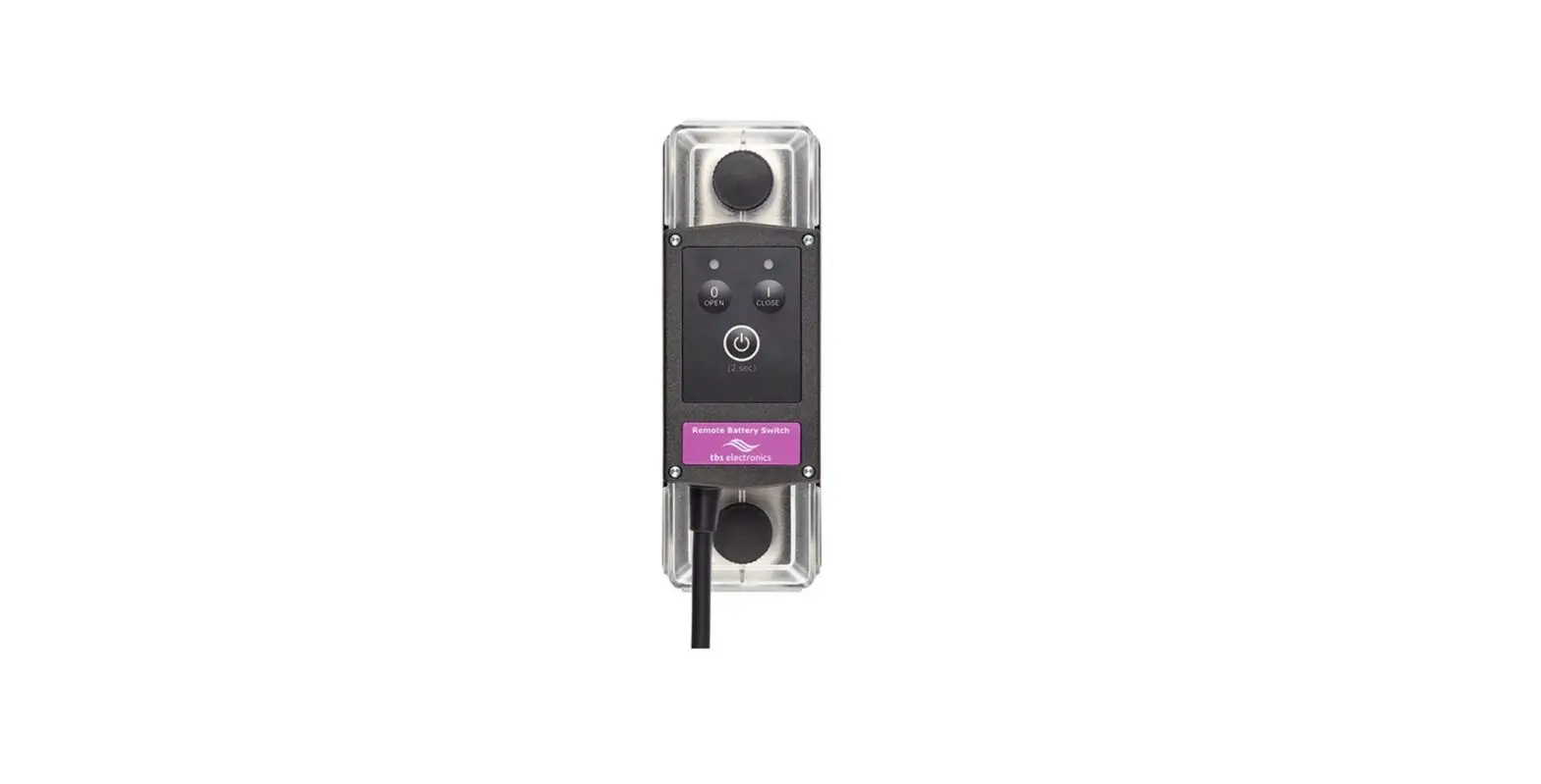
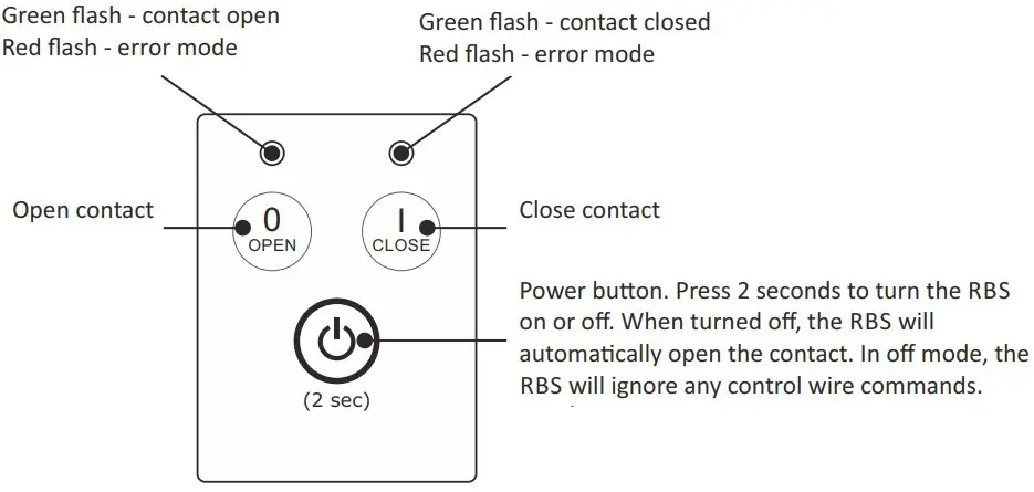
- Local Open and Close buons on top, to manually override the switch state.
- 5 wire interface cable for external control by panel switch, baery monitor or BMS. Compable with two wire or single wire On/Off control. Includes status wire for controlling indicator light or providing feedback to BMS.
- Stainless steel studs, washers and nuts for opmal corrosion resistance
- Unique grid opmized footprint allows space saving arrangements with other DC Modular products.
- Special fiber reinforced plasc housing offers excellent high temperature properes, good chemical resistance and high strength.
- Robust transparent covers with breakouts to allow wire access from any direcon.
- Smart terminal design allows dual mirrored cable lug connecons.
RBS specificaons
| Parameter | DCM-RBS-12-500 (art# 5074510) | DCM-RBS-24-500 (art# 5074520) |
| Contact circuit (electrical) | ||
| Rated voltage | 60Vdc | |
| Nominal current @ 25°C | 500A (see Precaution #2) | |
| Cranking current (1 minute) | 1000A | |
| Nominal make / break current | 500A (0 .. 34Vdc)350A (35 .. 60Vdc) | |
| Peak make / break current ¹⁾ | 1600A (0 .. 34Vdc)1200A (35 .. 60Vdc) | |
| Control circuit (electrical) | ||
| Coil / supply voltage (+Vdc) | 7.5 .. 17Vdc | 15 .. 34Vdc |
| Coil / supply current (idle state) | < 100μA | |
| Coil / supply current (state change) | < 6A | < 3A |
| Control wire supply current | < 3mA (when active) | |
| Control wire threshold voltage | > 5Vdc | |
| General | ||
| Remote control ²⁾ | By control wires (length 40cm, max. 15m) | |
| Local control | On/Standby, Close contact, Open contact | |
| Indicators | Contact open, Contact close, Error and Setup | |
| Protected against | High temperature, High/Low supply voltage, Ignition (ISO 8846) | |
| Mechanical life | 100000 cycles | |
| Electrical life | 10000 cycles (@ 400A/24V/resistive) | |
| Operating temperature range | -20 .. +60°C | |
| Connection studs / DCM grid size | M10 / 1 x 3 | |
| Protection class / weight | IP 65 / 800 grams | |
| Standards | EMC: 2014/30/EU & UNECE Regulation 10, Low voltage Directive: 2014/35/EU, RoHS: 2011/65/EU, ISO 8846 | |
Note : the given specificaons are subject to change without noce NB: bovenstaande gegevens kunnen zonder aankondiging van de fabrikant veranderen
- When switching in the upper voltage range, it is advised to install a proper pre charge circuit to keep the peak make current significantly below this value
- Panel switch with LED indicator oponally available (Art. no. 5095000-1)
TBS Electronics BV | De Marowijne 3 | 1689AR Zwaag | The Netherlands | www.tbs-electronics.com