tbs electronics DC Modular 500A Remote Battery Switch RBS
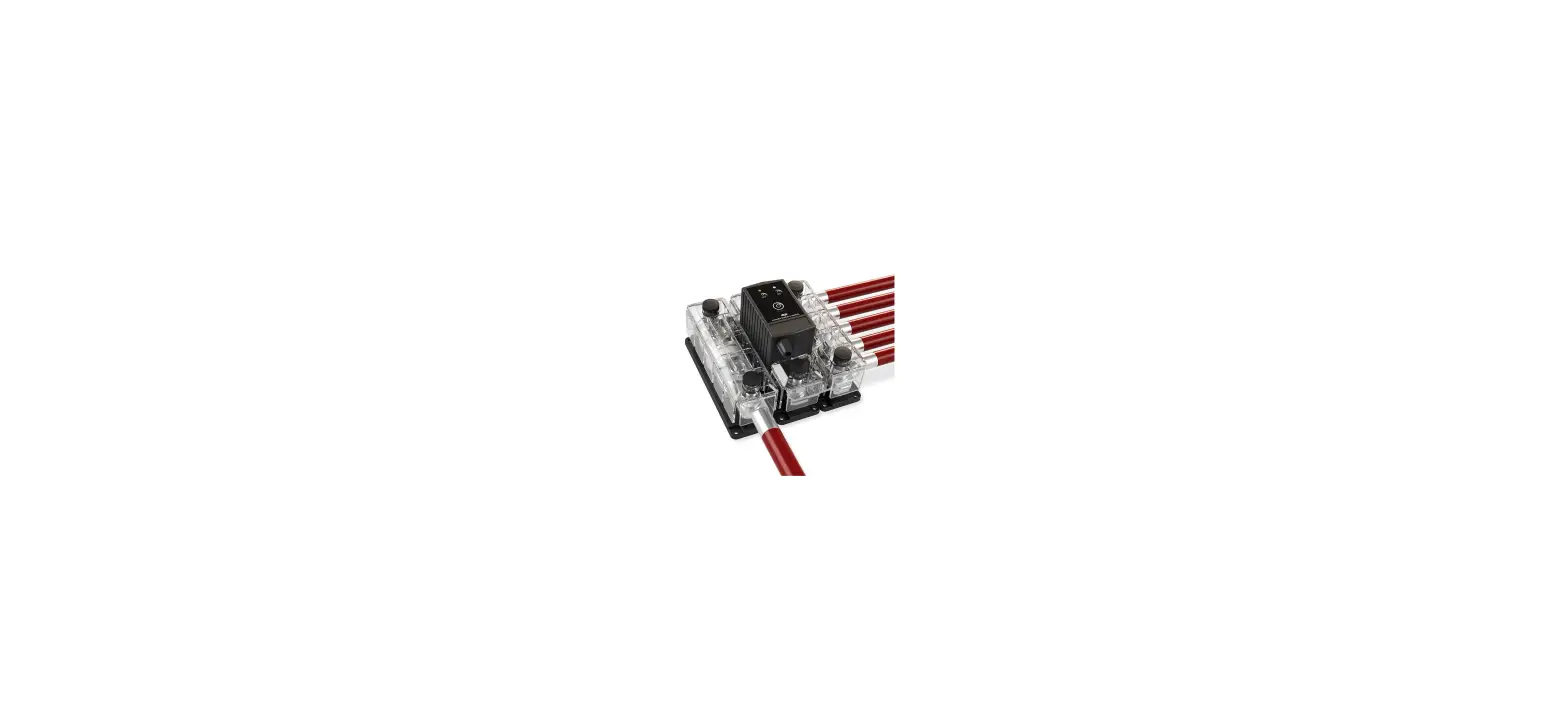
Main cable installation
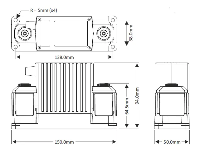
Dimension
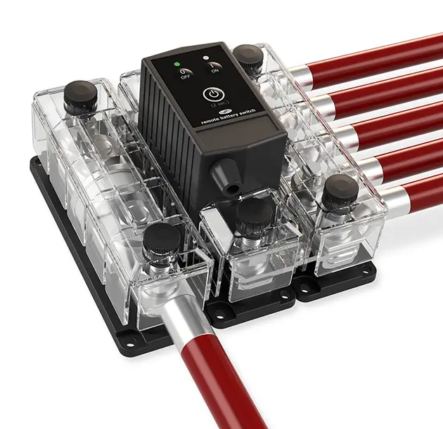
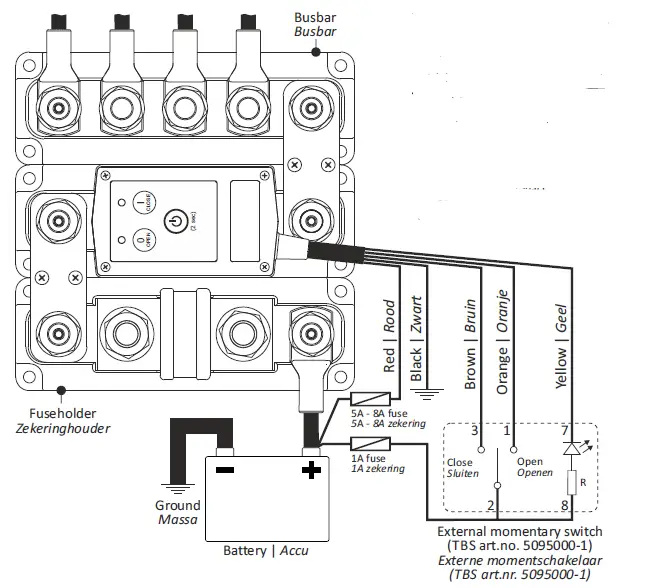
Wiring example
Error table
| Error table (both LEDs flashing red) | |
| Cause | Remedy |
| Supply voltage too low | Increase supply voltage |
| Supply voltage too high | Decrease supply voltage |
| RBS Temperature too high | Reduce the contact current, check all cable connections |
| Contacts are welded | Replace the RBS |
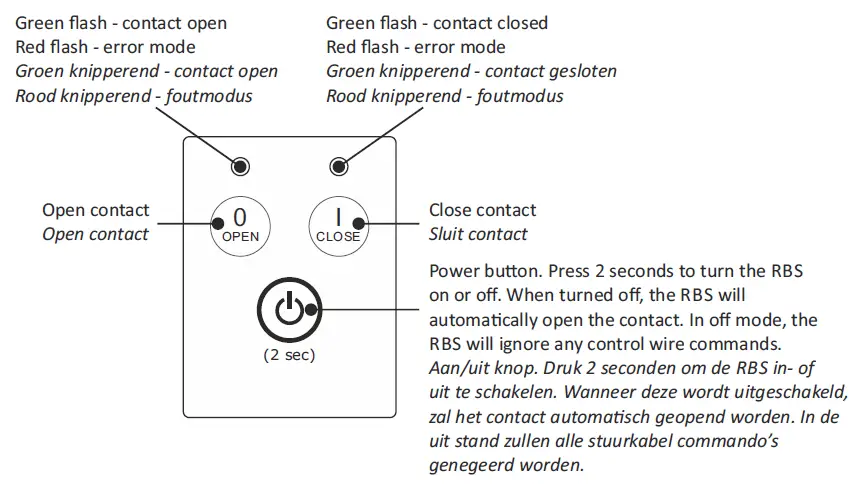
General operation
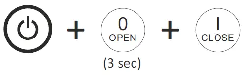
Change control mode
When in off mode, press all three buttons simultaneously for three seconds to enter the setup mode:
 Step through the control modes by pressing the OPEN (up) or CLOSE (down)
 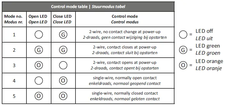 When the desired control mode is selected, press the Power button for 2 seconds to save the setting. Press the Power button again for 2 seconds to activate the RBS with the new con
- Modes 1, 2 & 3:
Vdc pulse on brown wire to close, +Vdc pulse on orange wire to - Mode 4:
+ Vdc continuous on brown wire to close, 0Vdc on brown wire to open. Orange wire not used. - Mode 5:
Vdc continuous on brown wire to open, 0Vdc on brown wire to close. Orange wire not used
EN Installation details
Precautions
- Please install this product in a dry indoor location, as close as possible to the battery. To be installed only by qualified technicians.
- To avoid fire hazards, use correctly sized cables which are suitable to carry the expected load currents in your application. The maximum continuous RBS current rating of 500A is only valid when a total cable size of at least 200mm² is connected to the M10 studs. Or when the RBS is part of a DC Modular system containing large busbars and fuseholders.
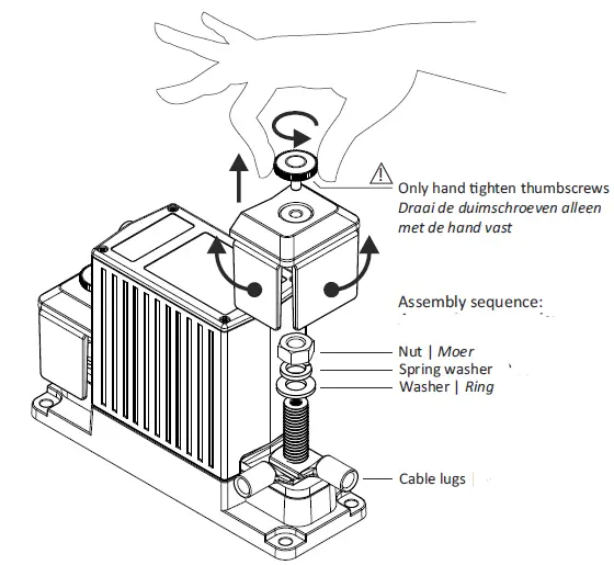
- To avoid fire hazards or damaging the RBS, please make sure that all nuts are securely ghtened. Please apply our recommended torque ra ng of 22Nm for the M10 nuts.
- To avoid fire hazards or damaging the RBS, please make sure that spring- and flat washers are always placed directly below the nut. Never place washers between: busbar and cable lug, multiple cable lugs on the same stud, busbar and linkplate or cable lug and linkplate.
- Please make sure that all connection cables are properly strain relieved, to avoid excessive mechanical stress on the RBS.
RBS features
- Smart high current tic latching relay, draws virtually no current in On (Close) or Off (Open) state.
- Silver alloy contacts and silver plated copper busbars, for maximum conductivity and high reliability when switching live loads.
- Local Open and Close buttons on top, to manually override the switch state.
- 5 wire interface cable for external control by panel switch, battery monitor or BMS. with two wire or single wire On/Off control. Includes status wire for controlling indicator light or providing feedback to BMS.
- Stainless steel studs, washers and nuts for op mal corrosion resistance.
- Unique grid optimized footprint allows space saving arrangements with other DC Modular products.
- Special fiber reinforced plastic housing offers excellent high temperature proper es, good chemical resistance and high strength.
- Robust transparent covers with breakouts to allow wire access from any direction.
- Smart terminal design allows dual mirrored cable lug connections.
RBS specifications
| Parameter | DCM-RBS-12-500 (art# 5074510) | DCM-RBS-24-500 (art# 5074520) |
| Contact circuit (electrical) | ||
| Rated voltage | 60Vdc | |
| Nominal current @ 25°C | 500A (see Precaution #2) | |
| Cranking current (1 minute) | 1000A | |
| Nominal make / break current | 500A (0 .. 34Vdc) 350A (35 .. 60Vdc) | |
| Peak make / break current | 1600A (0 .. 34Vdc) 1200A (35 .. 60Vdc) | |
| Control circuit (electrical) | ||
| Coil / supply voltage (+Vdc) | 7 .. 17Vdc | 14 .. 34Vdc |
| Coil / supply current (idle state) | < 100μA | |
| Coil / supply current (state change) | < 4A | < 3A |
| General | ||
| Remote control ¹⁾ | By control wires (length 40cm, max. 15m) | |
| Local control | On/Standby, Close contact, Open contact | |
| Indicators | Contact open, Contact close, Error and Setup | |
| Protected against | High temperature, High/Low supply voltage, Ignition (ISO 8846) | |
| Mechanical life | 100000 cycles | |
| Electrical life | 10000 cycles (@ 400A/24V/resistive) | |
| Operating temperature range | -20 .. +60°C | |
| Connection studs / DCM grid size | M10 / 1 x 3 | |
| Protection class / weight | IP 65 / 800 grams | |
| Standards | EMC: 2014/30/EU & UNECE Regulation 10, Low voltage Directive: 2014/35/EU, RoHS: 2011/65/EU, ISO 8846 | |
TBS Electronics BV | De Marowijne 3 | 1689AR Zwaag | The Netherlands | www.tbs-electronics.com


