![]()
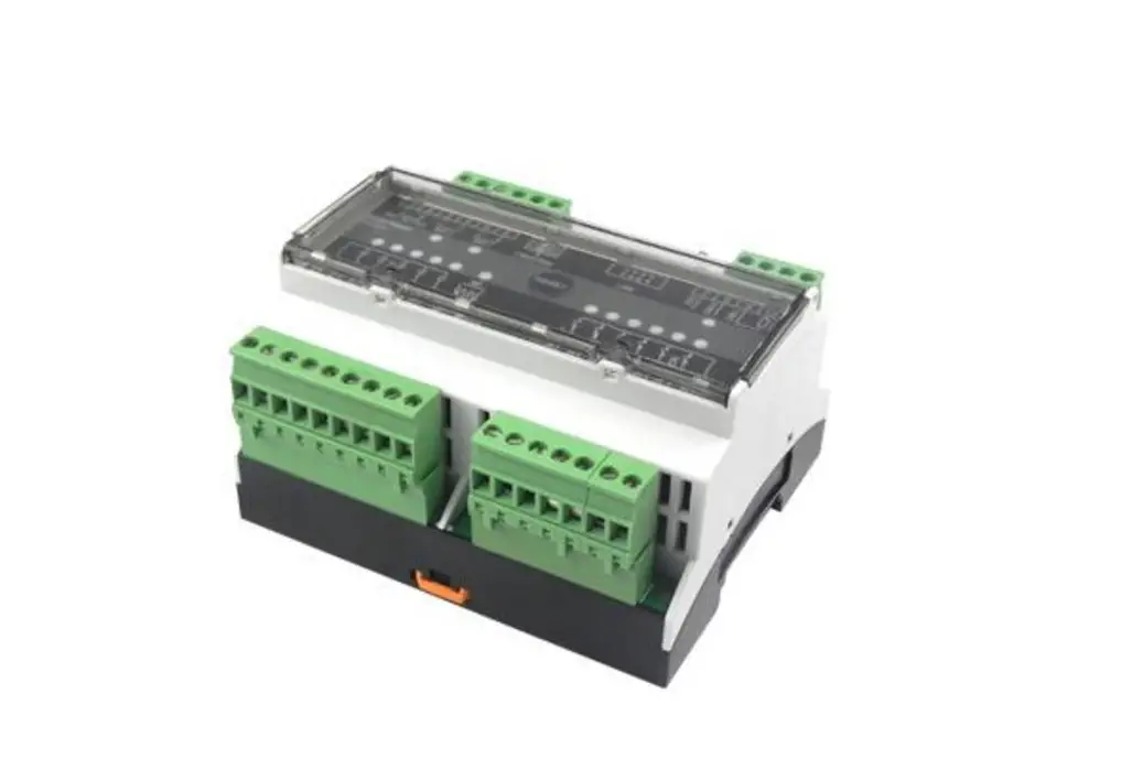
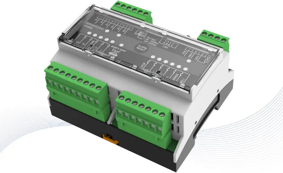
RPU560A
REDUNDANT PROTECTION UNIT
USER MANUAL
SMARTGEN(ZHENGZHOU) TECHNOLOGY CO.,LTD.
![]() Chinese trademark
Chinese trademark
![]() English trademark
English trademark
SmartGen — make your generator smart
SmartGen Technology Co., Ltd.
No.28 Jinsuo Road, Zhengzhou, Henan Province, China
Tel: +86-371-67988888/67981888/67992951
+86-371-67981000(overseas)
Fax: +86-371-67992952
Web: www.smartgen.com.cn/
www.smartgen.cn/
Email: [email protected]
All rights reserved. No part of this publication may be reproduced in any material form (including photocopying or storing in any medium by electronic means or other) without the written permission of the copyright holder.
Applications for the copyright holder’s written permission to reproduce any part of this publication should be addressed to Smartgen Technology at the address above.
Any reference to trademarked product names used within this publication is owned by their respective companies.
Smartgen Technology reserves the right to change the contents of this document without prior notice.
Table 1 Software Version
Date | Version | Note |
| 2015-08-10 | 1.0 | Original Release |
| 2015-12-15 | 1.1 | Change the name Security Module to Redundant Protection Unit |
| 2021-08-15 | 1.2 | Add the emergency stop break wire detection, and change the voltage input description of power supply. |
| 2022-10-10 | 1.3 | Update company logo and manual format. |
This manual is suitable for RPU560A redundant protection unit only.
Table 2 Notation Clarification
| Sign | Instruction |
| Highlights an essential element of a procedure to ensure correctness. | |
| Indicates a procedure or practice, which, if not strictly observed, could result in damage or destruction of equipment. | |
| Indicates a procedure or practice, which could result in injury to personnel or loss of life if not followed correctly. |
1 OVERVIEW
RPU560A Redundant Protection Unit is a unit that can autonomously maintain and protect the engine running. The module is connected to HMC9000/HMC6000 via CANBUS port. All parameters and shutdown alarm types can be checked on the master controller. It can be widely used in marine emergency units, main propulsion units, main generator units and pumping units.
2 PERFORMANCE AND CHARACTERISTICS
➢ Speed sensor enables accurate control and protection of the running engine;
➢ Optional working mode; one is synchronized with master controller to protect engine normal running; the other is protect engine automatically when master controller failure occurs.
➢ 4 digital shutdown inputs;
➢ 5 relay outputs: shutdown output, fuel output, common warning output, common shutdown output, auxiliary output;
➢ Emergency shutdown input port: after emergency shutdown is initiated, regardless of whether master controller failure occurred or not, shutdown signal will still be sent;
➢ Override mode, in which only overspeed shutdown and emergency shutdown signals will be able to stop the unit;
➢ Modular design, compact structure, small size and easy use.
3 TECHNICAL PARAMETERS
Table 3 Technical Parameters
Item | Details |
| Working Voltage | DC18.0V~DC35.0V |
| Power Consumption | <2.5W |
| Shutdown Output | 7A relay output, break wire detection function |
| Fuel Output | 16A relay output, break wire detection function |
| Common Warning Output | 7A relay output |
| Common Shutdown Output | 7A relay output |
| Auxiliary Output | 7A relay output |
| Case Dimension | 107.6mm x 89.7mm x 60.7mm |
| Working Temperature | (-25~+70)°C |
| Working Humidity | (20~93)%RH |
| Storage Temperature | (-30~+80)°C |
| Weight | 0.27kg |
4 OPERATION
4.1 MAIN PROTECTED MODE
RPU560A redundant protection unit will detect engine parameters and shutdown inputs automatically to protect the engine in real time whether the main module is active or not. If overspeed shutdown or other shutdown alarm input is occurred, the stop relay is energized while the fuel relay is disengaged, then the common shutdown relay is engaged. When the engine stops successfully, users can reset the alarm by pressing reset button mounted on the HMC9000/HMC6000 panel or by pressing the reset button contained within the RPU560A module.
4.2 STANDBY PROTECTED MODE
- When master control is active (CANBUS communication is normal), if the engine speed has exceeded the fuel output speed, the fuel relay is energized. Only the active emergency shutdown input and overspeed signal will be able to stop the generator.
- When master control is deactivated (CANBUS communication is failed), if overspeed shutdown or other shutdown signal is detected, the stop relay is energized while the fuel relay is disengaged, then the common shutdown relay is engaged. When the engine stops successfully, users can reset the alarm by pressing reset button.
- In override mode, if master control is deactivated, only overspeed shutdown and emergency shutdown signals will be able to stop the unit.
5 PROTECTION
5.1 WARNINGS
When the warnings mentioned below are initiated, the alarm message will be displayed on LCD and the common relay is energized.
Warning types are as follows:
Table 4 Warnings
No. | Warning type | Detection range | Description |
| 1 | Battery 1 Over Volt | Always active | Active when the battery voltage has fallen below the pre-set threshold and last for 20s. Then lamp BAT.1, BAT.2 will blink and the common warn relay outputs at the same time. |
| 2 | Battery 2 Over Volt | ||
| 3 | Battery 1 Under Volt | ||
| 4 | Battery 2 Under Volt | ||
| 5 | Input 1 BW Warn | When the controller detects wire disconnection, the disconnection indicators begin to blink and the common warn relay outputs, and the corresponding information will be displayed on the LCD screen. | |
| 6 | Input 2 BW Warn | ||
| 7 | Input 3 BW Warn | ||
| 8 | Input 4 BW Warn | ||
| 9 | Override input BW Warn | ||
| 10 | Shutdown output BW Warn | ||
| 11 | Fuel BW Warn | ||
| 12 | Speed BW Warn | ||
| 13 | EM. STOP Break Wire Warn |
5.2 SHUTDOWN ALARM
If shutdown alarm signal is detected, shutdown relay and common shutdown relay activate while fuel relay deactivates.
Table 5 Shutdown Alarms
No. | Alarm Type | Detection range | Description |
| 1 | Emergency Shutdown | Always active | After shutdown alarm signal is initiated, shutdown relay and common shutdown relay are activated while fuel relay deactivates. When failure shutdown is active, the corresponding lamp will be always initiated. |
| 2 | Input 1 Shutdown | Always active | When failure shutdown input is active and engine speed has exceeded or been equal with pre-set value, shutdown relay and common shutdown relay are activated while fuel relay deactivates. When failure shutdown is active, the corresponding lamp will be always initiated, and the controller possesses with break wire detection function (it can be defined by users). |
| 3 | Input 2 Shutdown | ||
| 4 | Input 3 Shutdown | ||
| 5 | Input 4 Shutdown |
6 PARAMETER CONFIGURATION
RPU560A redundant protection unit parameters can only be configured via PC software (the LINK port of RPU560A must be connected with SG72 transfer module and then connect with PC).
Table 6 Parameter Configuration
Parameter | Range | Factory default value |
| 1. Input 1 Delay | (0-20.0)s | 2.0s |
| 2. Input 1 BW Detection | (0-1) | 0: Not detect |
| 3. Input 1 Alarm Speed | (0-200)% | 0 |
| 4. Input 2 Delay | (0-20.0)s | 2.0s |
| 5. Input 2 BW Detection | (0-1) | 0: Not detect |
| 6. Input 2 Alarm Speed | (0-200)% | 0 |
| 7. Input 3 Delay | (0-20.0)s | 2.0s |
| 8. Input 3 BW Detection | (0-1) | 0: Not detect |
| 9. Input 3 Alarm Speed | (0-200)% | 0 |
| 10. Input 4 Delay | (0-20.0)s | 2.0s |
| 11. Input 4 BW Detection | (0-1) | 0: Not detect |
| 12. Input 4 Alarm Speed | (0-200)% | 0 |
| 13. Override Input BW Detection | (0-1) | 0: Not detect |
| 14. EM. Stop BW Detection Enable | (0-1) | 0: Not detect |
| 15. Output 1 Set | (0-10) | 1: Master Control Fail |
| 16. Output 1 Type | (0-1) | 0: Normally open |
| 17. Flywheel Teeth | (10-300) | 118 |
| 18. Rated Speed | (0-5999)r/min | 1500 r/min |
| 19. Fuel Output | (0-200)% | 25%. The fuel relay is active when the speed has exceeded the default value while deactivated when the speed has fallen below the default value. |
| 20. Over Speed Shut | (0-200)% | 115% |
| 21. Over Speed Delay | (0-3600)s | 1s |
| 22. Over Speed Warn | (0-200)% | 110% |
| 23. Over Speed Return | (0-200)% | 108% |
| 24. Battery Rated Volt | (0-60.0)V | 24.0V |
| 25. Battery 1 Over Volt Warn | (0-200)% | 125% |
| 26. Battery 2 Over Volt Warn | (0-200)% | 125% |
| 27. Battery 1 Under Volt Warn | (0-200)% | 80% |
| 28. Battery 2 Under Volt Warn | (0-200)% | 80% |
| 29. Work Mode | (0-1) | 0: Main protected mode The RPU560A module will detect engine parameters and alarm information automatically to protect the engine in real time whether the master module is active or not. 1: Standby protected mode The RPU560A module will protect engine automatically when the master module is deactivated. |
7 OUTPUT PORT FUNCTION DEFINITION
Table 7 Output Port Function Definition
No. | Contents | Description |
| 0 | Not Used | |
| 1 | Master Module Fail | Active when the master module is deactivated. |
| 2 | Main Battery Supply | Active when the main battery supply feed. |
| 3 | Standby Battery Supply | Active when the standby battery supply feed. |
| 4 | Common Alarm | Active when warning or shutdown alarm occurs. |
| 5 | Normal Running | Active when working normally; deactivated when fail. |
| 6 | Overspeed Shutdown | Active when overspeed shutdown occurs. |
| 7 | Reserved | |
| 8 | Reserved | |
| 9 | Reserved | |
| 10 | Reserved |
8 TERMINAL CONNECTIONS
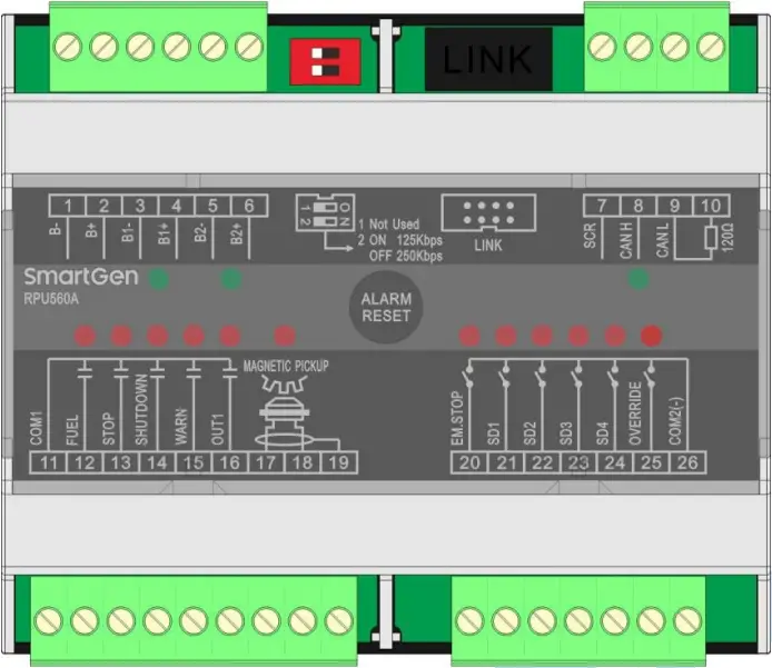
Fig.1 Terminal Description Drawing
Table 8 Terminal Description
Terminal | Function | Cable Size | Description |
| 1. | B- | 2.5mm² | Power supply negative input. |
| 2. | B+ | 2.5mm² | Power supply positive input. |
| 3. | B1- | 2.5mm² | 1# power supply negative input. |
| 4. | B1+ | 2.5mm² | 1# power supply positive output |
| 5. | B2- | 2.5mm² | 2# power supply negative input. |
| 6. | B2+ | 2.5mm² | 2# power supply positive input. |
| 7. | SCR (CANBUS) | 0.5mm² | Connect HMC9000/HMC6000 CANBUS port. Impedance-120Ω shielded wire with its one end connected to SCR is recommended. |
| 8. | CAN(H) (CANBUS) | 0.5mm² | |
| 9. | CAN(L) (CANBUS) | 0.5mm² | |
| 10. | 120Ω | 0.5mm² | |
| 11. | COM1 | 2.5mm² | Common output port |
| 12. | FUEL | 1.0mm² | Output as working indication when the module detects engine speed exceeded preset “fuel output speed”, deactivate when shutdown, and possess break wire detection function. |
| 13. | STOP | 1.0mm² | Output when the module detects a warning alarm, connect to shutdown electromagnet, and possess break wire detection function. |
| 14. | SHUTDOWN | 1.0mm² | Output when the module detects a warning alarm, alarm status will be locked to save, and it can be reset by pressing reset button. |
| 15. | WARN | 1.0mm² | Output when the module detects a warning alarm, the status will not be locked to save. |
| 16. | OUT1 | 1.0mm² | It can be configured by users; output after it is energized. |
| 17. | MAGNETIC PICKUP | 0.5mm² | Speed sensor input with break wire detection function. |
| 18. | 0.5mm² | ||
| 19. | 0.5mm² | ||
| 20. | EM.STOP | 0.5mm² | Emergency shutdown input port (connect to COM2(-) to activate) NOTE: Break wire detection function can be configured; it needs to connect COM2(-) port with a 10kΩ resistance. |
| 21. | SD1 | 0.5mm² | Failure shutdown input port (connect to COM2(-) to activate); It can control engine to stop when it is active. NOTE: Break wire detection function can be configured; it needs to connect COM2(-) port with a 10kΩ resistance. |
| 22. | SD2 | 0.5mm² | |
| 23. | SD3 | 0.5mm² | |
| 24. | SD4 | 0.5mm² | |
| 25. | OVERRIDE | 0.5mm² | Override mode (connect to COM2(-) to activate); In this mode, only Emergency shutdown and Over speed shutdown can stop the engine in case of main controller deactivate. |
| 26. | COM2(-) | 0.5mm² | Common input port. |
| ALARM RESET | Pressing this button can reset the alarm. | ||
| NOTE: When the communication of CAN and HMC9000/HMC6000 is normal, then CAN indicator will blink, otherwise it will be distinguished. | |||
9 SYSTEM CONNECTION DIAGRAM
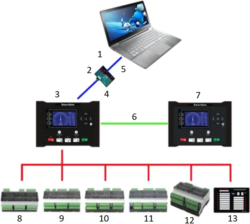
Fig.2 System Connection Diagram
- Remote Monitor
- RS485
- HMC9000
Main Control Module - SG72 COM Module
- USB
- CANBUS COM
(REMOTE) - HRM3300
Remote Monitor Module - DOUT16A
- AIN16-PT
PT100 - AIN16-C
4-20mA - AIN16-M01
- RPU560A
- LA16
10 APPLICATION DIAGRAM
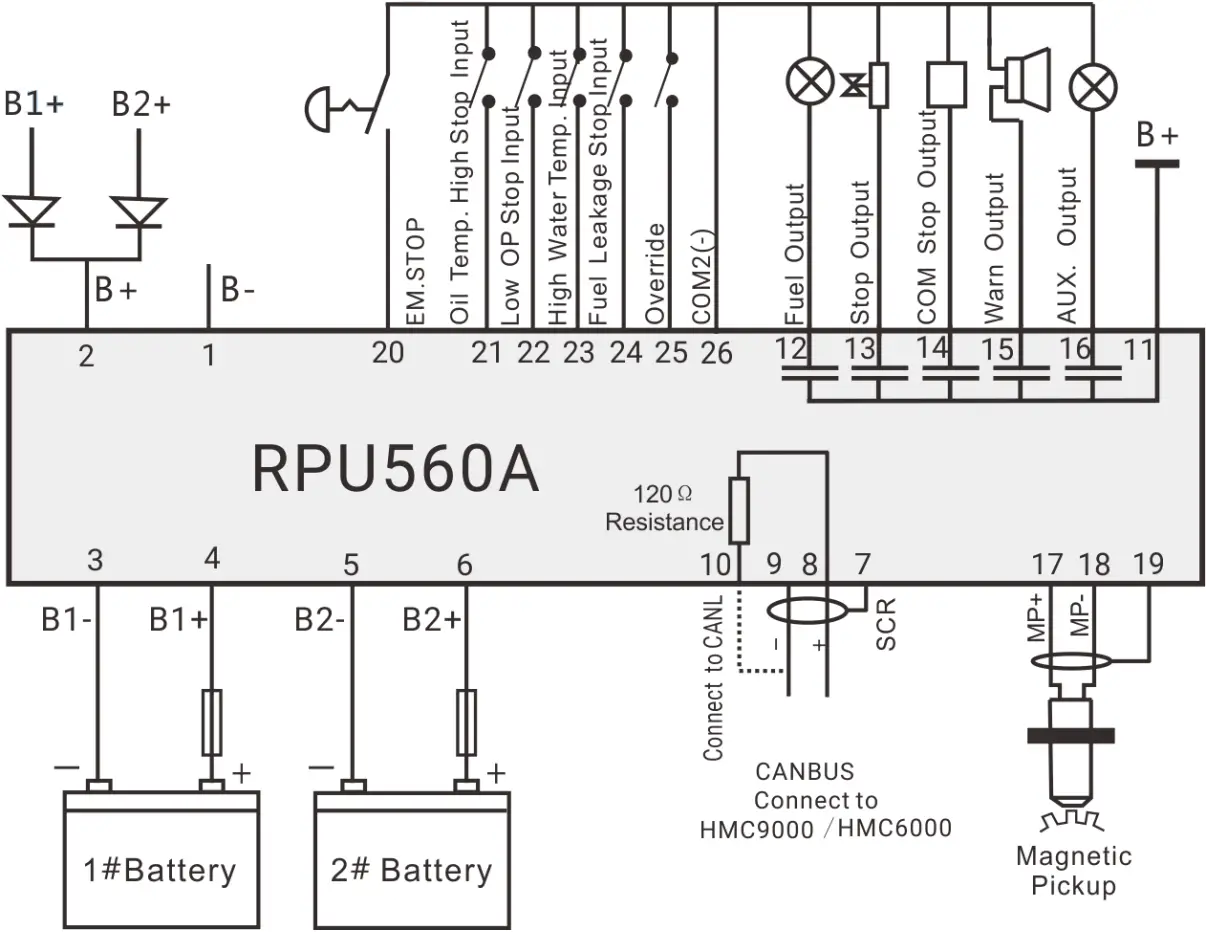
Fig.3 Typical Application Diagram
11 INSTALLATION
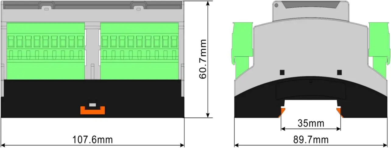
Fig.4 Case Dimensions
12 TROUBLESHOOTING
Table 9 Troubleshooting
| Problem | Possible Solution |
| Controller no response with power. | Check start batteries; Check controller connection wirings; |
| CANBUS communication failure | Check if CANBUS wires are connected in the opposite way; Check if 120Ω resistance is connected; Check if Baud rate of the dial switch is correct. |
RPU560A Redundant Protection Unit User Manual


