
Altronix T1M1LCK1 Mercury Access and Power
Models Include
- 4 Door Kits with Fused Outputs: T1M1LCK1
Accommodates one (1) Intelligent Dual Reader Controller and one (1) Dual Reader Interface Modules. - 2 Door Kits with Fused Outputs: T1M1LCK2
Accommodates one (1) Intelligent Controller and one (1) Dual Reader Interface Module. - 4 Door Kits with Fused Outputs: T1M1LCK3
Accommodates up to two (2) Dual Reader Interface Modules. - Each fully assembled kit includes:
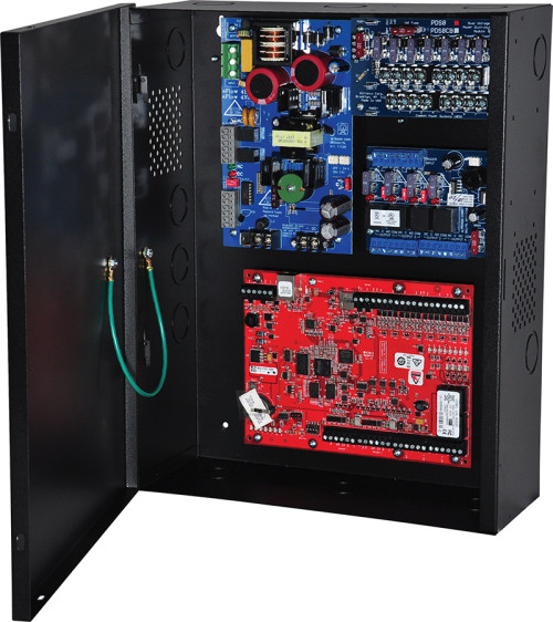
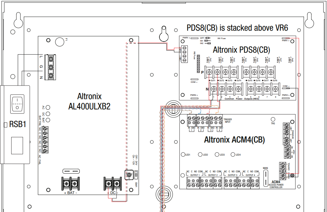
- Trove1 enclosure with TM1 Altronix/Mercury backplane
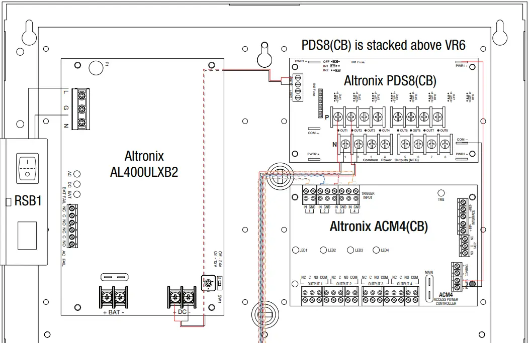
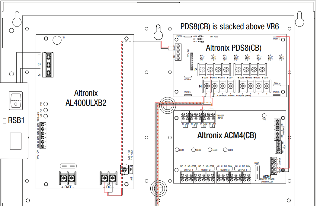
- One (1) AL400ULXB2 – Power Supply/Charger
- One (1) ACM4 – Fused Access Power Controller
- One (1) PDS8 – Dual Input Fused Power Distribution Module
- One (1) VR6 – Voltage Regulator
- One (1) Rocker Switch Bracket with One (1) Rocker Switch
Installation Guide
All registered trademarks are property of their respective owners.
- nstalling Company: _________________________
- Service Rep. Name: ____________________________________________
- Address: _________________________________________________________
- Phone #: ___________________________
Overview
Altronix Trove Plus kits are pre-wired, pre-assembled and consist of Trove1M1 enclosure/backplane with factory installed Altronix power supply/charger and sub-assemblies, wire harnesses and finger duct.
Configuration Chart
|
Altronix Model Number |
115VAC 60Hz Input Current (A) |
Power Supply Board Input Fuse Rating |
Power Supply Board Battery Fuse Rating | Nominal DC Output Voltage |
Maximum Supply Current for Main Outputs on Power Supply board and ACM4(CB) Access Power Controller’s outputs | Fail-Safe/Fail-Secure or Dry Form “C” Outputs | ACM4(CB) Board Input Fuse (PTC) Rating | ACM4(CB) Board Output Fuse (PTC) Rating | PDS8(CB) Board Input Fuse (PTC) Rating | PDS8(CB) Board Output Fuse (PTC) Rating | |
| Power Supply 1 | Power Supply 2 | ||||||||||
|
Output Range (VDC) |
Output Range (VDC) | ||||||||||
| T1M71LCK1 |
3.0 |
5A/ 250V |
15A/ 32V |
20.17- 26.4 |
20.17- 26.4 |
24VDC @ 3.8A |
4 |
10A/ 250V |
3A/ 250V |
10A/ 250V |
3A/ 250V |
| T1M71LCK2 | |||||||||||
| T1M71LCK3 | |||||||||||
| T1M71LCK1D |
10A/ 250V |
2.5A |
9A |
2.5A | |||||||
| T1M71LCK2D | |||||||||||
| T1M71LCK3D | |||||||||||
Installation Instructions
Wiring methods shall be in accordance with the National Electrical Code/NFPA 70/ANSI, and with all local codes and authorities having jurisdiction. Product is intended for indoor use only.
- Remove backplane from enclosure. Do not discard hardware.
- Mark and predrill holes in the wall to line up with the top three keyholes in the enclosure. Install three upper fasteners and screws in the wall with the screw heads protruding. Place the enclosure’s upper keyholes over the three upper screws; level and secure.
Mark the position of the lower three holes. Remove the enclosure. Drill the lower holes and install the three fasteners.
Place the enclosure’s upper keyholes over the three upper screws. Install the three lower screws and make sure to tighten all screws. - Mount included UL Listed tamper switch (Altronix Model TS112 or equivalent) in desired location, opposite hinge. Slide the tamper switch bracket onto the edge of the enclosure approximately 2” from the right side (Fig. 1, pg. 2). Connect tamper switch wiring to the Access Control Panel input or the appropriate UL Listed reporting device. To activate alarm signal open the door of the enclosure.
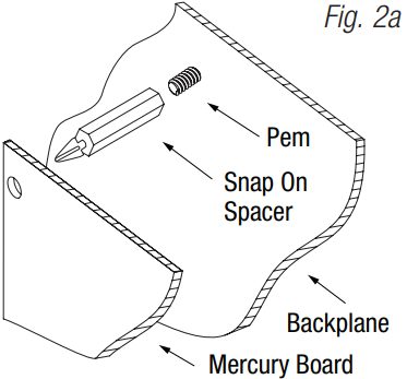
- Mount Mercury modules to backplane(s), refer to page 3.
- Refer to the ULXB Power Supply/Charger Installation Guide for AL400ULXB2 and corresponding Installation Guides for PDS8(CB), VR6, and ACM4(CB) for further installation instructions.


T1M1LCK1(D): Configuration of Mercury Boards
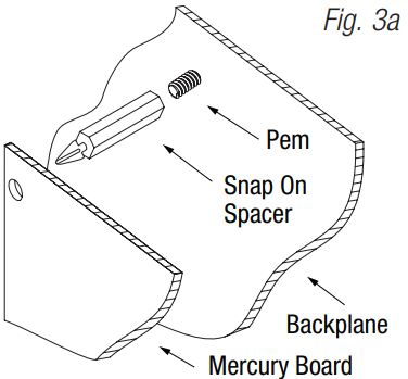
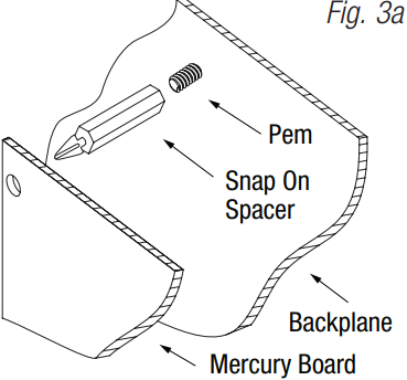
- Position access controller module over corresponding spacers and depress onto snap on spacers (Fig. 3, pg. 4).
- Mount backplane to enclosure with hardware.
Access Controller Position Chart for the Following Models
| Mercury Access Controller | Pem Mounting |
| LNL-2220 / LP1502 / LP4502 | A |
| LNL-1320 / MR52 | B |

T1M1LCK2(D): Configuration of Mercury Boards
- Position access controller module over corresponding spacers and depress onto snap on spacers (Fig. 3, pg. 4).
- Mount backplane to enclosure with hardware.
Access Controller Position Chart for the Following Models
| Mercury Access Controller | Pem Mounting |
| LNL-3300 / LP2500 | A |
| LNL-1320 / MR52 | B |

T1M1LCK3(D): Configuration of Mercury Boards
- Position access controller module over corresponding spacers and depress onto snap on spacers (Fig. 3, pg. 4).
- Mount backplane to enclosure with hardware.
Access Controller Position Chart for the Following Models
| Mercury Access Controller | Pem Mounting |
| LNL-1320 / MR52 | A |
| LNL-1320 / MR52 | B |

Trove1 Enclosure Dimensions
(H x W x D approximate): 18” x 14.5” x 4.625” (457mm x 368mm x 118mm)


140 58th Street, Brooklyn, New York 11220 USA | phone: 718-567-8181 | fax: 718-567-9056
web site: www.altronix.com | e-mail: [email protected] | Lifetime Warranty


