Altronix Trove Series Trove1M1 Access and Power Integration
Access & Power Integration
Trove1M1
- Trove1 enclosure with Altronix & Mercury/LenelS2 backplane (TM1)
TM1
- Altronix & Mercury/LenelS2 backplane only
Trove2M2
- Trove2 enclosure with Altronix & Mercury/LenelS2 backplane (TM2)
TM2
- Altronix & Mercury/LenelS2 backplane only
TMV2
- Altronix & Mercury/LenelS2 Door Backplane. Fits Trove2 and Trove3 enclosures
Trove3M3
- Trove3 enclosure with Altronix & Mercury/LenelS2 backplane (TM3)
TM3
- Altronix & Mercury/LenelS2 backplane only
Installation Guide
Overview:
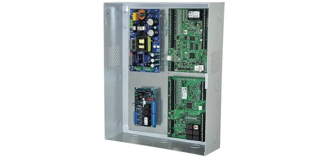
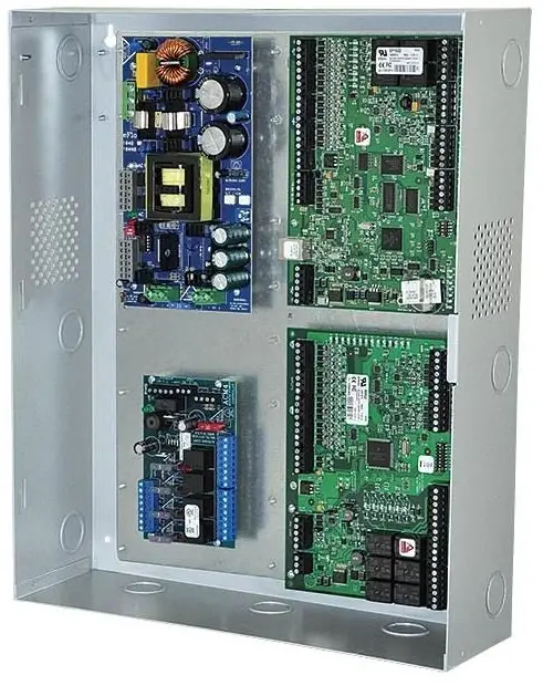
Altronix Trove1M1, Trove2M2 and Trove3M3 accommodate various combinations of Mercury/LenelS2 boards with or without Altronix power sup-plies and sub-assemblies for access systems.
Specifications:
16 Gauge backplane and enclosure with ample knockouts for convenient access.
- Trove1M1
- Trove1 enclosure with
- TM1 Altronix and Mercury/LenelS2 backplane.
- Includes: tamper switch, cam lock, lock nuts and mounting hardware. Enclosure Dimensions (H x W x D): 18” x 14.5” x 4.625” (457mm x 368mm x 118mm).
TM1
Altronix and Mercury/LenelS2 backplane.
- Includes mounting hardware.
- Dimensions (H x W x D): 16.625” x 12.5” x 0.3125” (422.3mm x 317.5mm x 7.9mm).
See TM1 Sub-Assembly Position Chart on Pg. 3 for the list of compatible sub-assemblies.
Trove2M2
Trove2 enclosure with TM2 Altronix and Mercury/LenelS2 backplane
- Includes: tamper switch, cam lock, lock nuts and mounting hardware. Enclosure Dimensions (H x W x D): 27.25” x 21.75” x 6.5” (692.2mm x 552.5mm x 165.1mm).
TM2
Altronix and Mercury/LenelS2 backplane.
- 16 Gauge backplane.
- Includes: lock nuts and mounting hardware.
- Dimensions (H x W x D): 25.375” x 19.375” x 0.3125” (644.5mm x 492.1mm x 7.9mm). See TM2 Sub-Assembly Position Charts on Pgs. 5, 7, 8 for the list of compatible sub-assemblies.
TMV2 – Optional Door Backplane
- Fits Altronix Trove2 and Trove3 enclosures.
- Dimensions (H x W x D): 23.75” x 18.125” x 0.3125” (603.3mm x 460.4mm x 7.9mm).
See TMV2 Sub-Assembly Position Chart on Pg. 9 for the list of compatible sub-assemblies.
Trove3M3
Trove3 enclosure with TM3 Altronix and Mercury/LenelS2 back-plane.
- Includes two (2) tamper switches, cam lock, lock nuts and mounting hardware.
- Enclosure Dimensions (H x W x D): 36.12” x 30.125” x 7.06” (917.5mm x 768.1mm x 179.3mm).
TM3
Altronix and Mercury/LenelS2 backplane.
- Includes: lock nuts and mounting hardware. Dimensions (H x W x D): 34” x 28” x 0.3125” (863.6mm x 711.2mm x 7.9mm). See TM3 Sub-Assembly Position Charts on Pgs. 10, 12 for the list of compatible sub-assemblies.
Agency Listings
(When Using Altronix and Mercury/LenelS2 Sub-Assemblies)
- UL 294 – 6th edition. Trove1M, Trove2M Trove3M Power Controllers: Line Security I, Destructive Attack I, Endurance IV, Stand-by Power II*. *Stand-by Power Level I if no battery is
- supplied. This Class B digital apparatus complies with Canadian ICES-003.
Environmental:
- Humidity and Temperature conditions as tested by UL (85%, +/-5% @ 30ºC +/-2ºC), ULC (93%, +/-2% @ 32ºC +/-2ºC).
Battery Backup:
- Trove1 enclosure accommodates up to two (2) 12VDC/7AH batteries.
- Trove2 enclosure accommodates up to two (2) 12VDC/12AH batteries.
- Trove3 enclosure accommodates up to four (4) 12VDC/12AH batteries.
Installation Instructions for Trove1, Trove2, Trove3:
Wiring methods shall be in accordance with the National Electrical Code/NFPA 70/ANSI, and with all local codes and authorities having jurisdiction. The product
Installation Instructions for Trove1, Trove2, Trove3:
Wiring methods shall be in accordance with the National Electrical Code/NFPA 70/ANSI, and with all local codes and authorities having jurisdiction. Product is intended for indoor use only. is intended for indoor use only.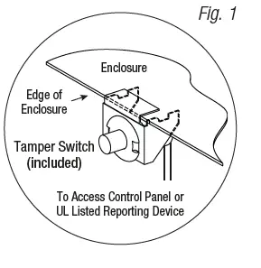
- Remove the backplane from the enclosure. Do not discard hardware.
- Mark and predrill holes in the wall to line up with the top three keyholes in the enclosure. Install two/three upper fasteners and screws in the wall with the screw heads protruding. Place the enclosure’s upper keyholes over the two/three upper screws; level and secure. Mark the position of the lower two/three holes. Remove the enclosure. Drill the lower holes and install the two/three fasteners. Place the enclosure’s upper keyholes over the two/three upper screws. Install the two/three lower screws and make sure to tighten all screws.
- Mount included UL Listed tamper switch(es) (Altronix Model TS112 or equivalent) in desired location, opposite hinge. Slide the tamper switch bracket onto the edge of the enclosure approximately 2” from the right side (Fig. 1, pg. 3). Connect tamper switch wiring to the Access Control Panel input or the appropriate UL Listed reporting device. To activate alarm signal open the door of the enclosure.
TM1 Sub-Assembly Position Chart for the Following Models:
| LenelS2 OnGuard / Mercury (HID) Platform Sub-Assemblies* | ||||
| LenelS2 | Mercury (HID) | Pem Mounting | Current Draw | Refer to |
| LNL-2220 | LP1502 |
A | 12-24VDC 500mA max. | LNL-2220 Quick Reference (QR50L-1002E – revision 2.022) |
| LNL-4420 | LP4502 | 12-24VDC 500mA max. | LNL-4420 Quick Reference (QR50L-1024E-LNL-4420 – revision 1.001) | |
| LNL-1100 | MR16IN | 12-24VDC 350mA max. (12VDC/300mA nom., 24VDC/220mA nom.) | LNL-1100 Series 2 Quick Reference (QR50L-1010E – revision 1.019) | |
| LNL-1200 | MR16OUT | 12-24VDC 1100mA max. (12VDC/850mA nom., 24VDC/450mA nom.) | LNL-1200 Series 2 Quick Reference (QR50L-1009E – revision 1.019) | |
| LNL-1320 | MR52 | 12-24VDC 550mA max. (12VDC/450mA nom., 24VDC/270mA nom.) | LNL-1320 Series 2 Quick Reference (QR50L-1007E – revision 1.020) | |
| LNL-2210 | LP1501 | D | 12VDC 900mA max. | LNL-2210 Series 2 Quick Reference (QR50L-1003E – revision 1.021) |
| LNL-1300e | MR62e | 12VDC 1100mA max. | LNL-1300e Quick Reference (QR50L-1023E – revision 1.000) | |
| LNL-1300 | MR50 | E | 12-24VDC 150mA max. (12VDC/110mA nom., 24VDC/60mA nom.) | LNL-1300 Series 2 Quick Reference (QR50L-1008E – revision 1.020) |
| LNL-3300 | LP2500 | G | 12-24VDC 300mA max. | LNL-3300 Quick Reference (QR50L-1001E – revision 2.023) |
| LNL-8000 | MUX8 | 12VDC 250mA max. | LNL-8000 Quick Reference (QR50L-1000E – revision 1.020) | |
| Altronix Sub-Assemblies | |||
| Sub-Assembly | Pem Mounting | Current Draw | Refer to |
| ACM4(CB) |
C | 12VDC @ 0.4A max. or 24VDC @ 0.2A max. | ACM4/ACM4CB Installation Instructions Rev. 052819 |
| MOM5 | 12-24VDC @ 55mA max. | MOM5 Installation Instructions Rev. 020119 | |
| PD4UL(CB) | N/A | PD4UL Installation Instructions Rev. 020119 | |
| PD4ULCB Installation Instructions Rev. 020119 | |||
| PD8UL(CB) | N/A | PD8UL Installation Instructions Rev. 020119 | |
| PD8ULCB Installation Instructions Rev. 020119 | |||
| PD16W(CB) | N/A | PD16W/PD16WCB Installation Instructions Rev. 020119 | |
| PDS8(CB) | N/A | PDS8/PDS8CB Installation Instructions Rev. 070116 | |
| VR6 | 24VDC @ 1.75A or 3.5A (Output: 5VDC or 12VDC @ 6A) | VR6 Installation Instructions Rev. 050517 | |
| LINQ2** | F | 12-24VDC @ 100mA max. | LINQ2 Installation Instructions Rev. 060514 |
| Altronix Power Supplies/Sub-Assemblies | ||||
| Sub-Assembly | Pem Mounting | Input Rating | Output Rating | Refer to |
| AL400ULXB2 |
B | 115VAC, 60Hz, 3.5A | 12VDC @ 4A or 24VDC @ 3A | ULXB Installation Instructions Rev. ULXB-020419 |
| AL600ULXB | 115VAC, 60Hz, 3.5A | 12VDC or 24VDC @ 6A | ULXB Installation Instructions Rev. ULXB-020419 | |
| AL1012ULXB | 115VAC, 60Hz, 2.6A | 12VDC @ 10A | ULXB Installation Instructions Rev. ULXB-020419 | |
| AL1024ULXB2 | 115VAC, 60Hz, 4.2A | 24VDC @ 10A | ULXB Installation Instructions Rev. ULXB-020419 | |
| eFlow4NB** | 120VAC, 60Hz, 3.5A | 12VDC or 24VDC @ 4A | eFlow Installation Instructions Rev. EFNB-021319 | |
| eFlow6NB** | 120VAC, 60Hz, 3.5A | 12VDC or 24VDC @ 6A | eFlow Installation Instructions Rev. EFNB-021319 | |
| eFlow102NB** | 120VAC, 60Hz, 3.5A | 12VDC @ 10A | eFlow Installation Instructions Rev. EFNB-021319 | |
| eFlow104NB** | 120VAC, 60Hz, 4.5A | 24VDC @ 10A | eFlow Installation Instructions Rev. EFNB-021319 | |
For detailed information, refer to the LenelS2 Hardware Installation Guide, DOC-600 r9.025 October 2018. ** LINQ2 can be installed when utilizing eFlow power supply/charger boards.
Installation Instructions for Sub-Assemblies to TM1:
Altronix Power Supplies/Chargers and/or Sub-Assemblies:
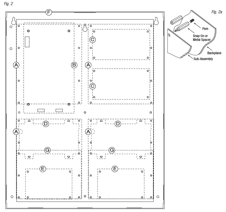
- Fasten spacers (provided) to pems that match the hole pattern for Altronix Power Supply/Chargers or Altronix Sub-Assembly boards (positions (B) and (C), Fig. 2, pg. 5). Use snap on nylon spacers for the upper two mounting holes in the board. Use metal spacers for the bottom mounting holes to provide sufficient grounding for the board.
- Affix boards to spacers (Fig. 2a, pg. 5) by pressing down the upper mounting holes onto nylon spacers. Use provided mounting screws to affix the lower mounting holes. Make sure that boards are locked onto spacers.
- For detailed information about installing and connecting Altronix sub-assemblies refer to the individual Installation Instructions listed in the Sub-Assembly Position Chart, pg. 4 and Trove Installation Guide, Rev. 101817.
- Fasten spacers onto metal pems configuration (A), (D), (E) or (G) of enclosure depending on the sub-assembly module (Fig. 2, pg. 5).
- Position access controller module over corresponding spacers and depress onto snap on spacers (Fig. 2a, pg. 5).
- Fasten backplane to Trove1 enclosure utilizing lock nuts (provided).

TM2 Sub-Assembly Position Chart for the Following Models:
| Altronix Power Supplies/Chargers | ||||
| Altronix | Pem Mounting | Input Rating | Output Rating | Refer to |
| AL400ULXB2 |
A | 115VAC, 60Hz, 3.5A | 12VDC @ 4A or 24VDC @ 3A | ULXB Installation Instructions Rev. ULXB-020419 |
| AL600ULXB | 115VAC, 60Hz, 3.5A | 12VDC or 24VDC @ 6A | ULXB Installation Instructions Rev. ULXB-020419 | |
| AL1012ULXB | 115VAC, 60Hz, 2.6A | 12VDC @ 10A | ULXB Installation Instructions Rev. ULXB-020419 | |
| AL1024ULXB2 | 115VAC, 60Hz, 4.2A | 24VDC @ 10A | ULXB Installation Instructions Rev. ULXB-020419 | |
| eFlow4NB* | 120VAC, 60Hz, 3.5A | 12VDC or 24VDC @ 4A | eFlow Installation Instructions Rev. EFNB-021319 | |
| eFlow6NB* | 120VAC, 60Hz, 3.5A | 12VDC or 24VDC @ 6A | eFlow Installation Instructions Rev. EFNB-021319 | |
| eFlow102NB* | 120VAC, 60Hz, 3.5A | 12VDC @ 10A | eFlow Installation Instructions Rev. EFNB-021319 | |
| eFlow104NB* | 120VAC, 60Hz, 4.5A | 24VDC @ 10A | eFlow Installation Instructions Rev. EFNB-021319 | |
| Altronix Sub-Assemblies | ||||
| Altronix | Pem Mounting | Current Draw | Refer to | |
| ACM4(CB) |
B | 12VDC @ 0.4A max. or 24VDC @ 0.2A max. | ACM4/ACM4CB Installation Instructions Rev. 052819 | |
| ACM8(CB) | 12VDC @ 0.5A max. or 24VDC @ 0.3A max. | ACM8/ACM8CB Installation Instructions Rev. 031819 | ||
| MOM5 | 12-24VDC 55mA max. | MOM5 Installation Instructions Rev. 020119 | ||
| PD4UL(CB) | N/A | PD4UL Installation Instructions Rev. 020119 | ||
| PD4ULCB Installation Instructions Rev. 020119 | ||||
| PD8UL(CB) | N/A | PD8UL Installation Instructions Rev. 020119 | ||
| PD8ULCB Installation Instructions Rev. 020119 | ||||
| PD16W(CB) | N/A | PD16W/PD16WCB Installation Instructions Rev. 020119 | ||
| PDS8(CB) | N/A | PDS8/PDS8CB Installation Instructions Rev. 070116 | ||
| VR6 | 24VDC @ 1.75A or 3.5A (Output: 5VDC or 12VDC @ 6A) | VR6 Installation Instructions Rev. 050517 | ||
| LINQ2* | C | 12-24VDC 100mA max. | LINQ2 Installation Instructions Rev. 060514 | |
LINQ2 can be installed when utilizing eFlow power supply/charger boards.
Installation Instructions for Altronix Power Supplies and/or Sub-Assemblies to TM2:
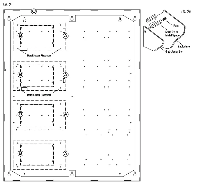
- Fasten spacers (provided) to pems that match the hole pattern for Altronix Power Supply/Chargers or Altronix Sub-Assembly boards (Fig. 3, pg. 7). Use snap on nylon spacers for the upper two mounting holes in the board. Use metal spacers for the bottom mounting holes to provide sufficient grounding for the board.
- Affix boards to spacers (Fig. 3a, pg. 7) by pressing down the upper mounting holes onto nylon spacers. Use provided mounting screws to affix the lower mounting holes. Make sure that boards are locked onto spacers.
- For detailed information about installing and connecting Altronix sub-assemblies refer to the individual Installation Instructions listed in the Sub-Assembly Position Chart, pg. 6 and Trove Installation Guide, Rev. 101817.
- Fasten backplane to Trove2 enclosure utilizing lock nuts (provided).

Installation Instructions for Mercury/LenelS2 Access Controllers to TM2:
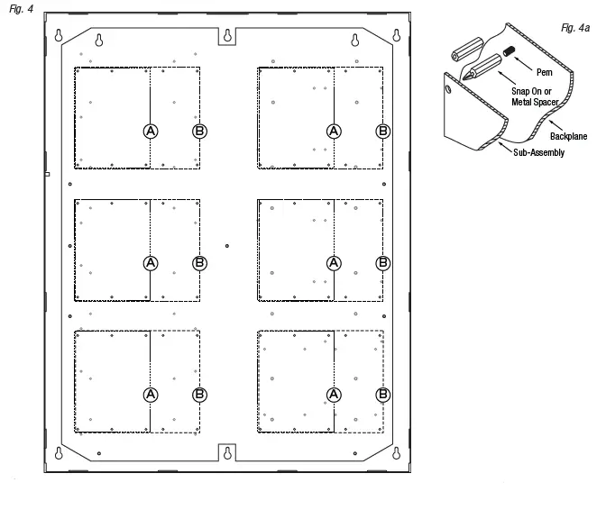
- Fasten snap on spacers onto metal pems configuration (A) (B) of backplane depending on the access controller (Fig. 4, pg. 8).
- Position access controller module over corresponding spacers and depress onto snap on spacers (Fig. 4a, pg. 8).
- Mount backplane to enclosure with hardware.
| LenelS2 | Mercury (HID) | Pem Mounting | Current Draw | Refer to |
| LNL-3300 | MR50 | A | 12-24VDC 300mA max. | LNL-3300 Quick Reference (QR50L-1001E – revision 2.023) |
| LNL-8000 | MUX8 | 12VDC 250mA max. | LNL-8000 Quick Reference (QR50L-1000E – revision 1.020) | |
| LNL-2220 | LP1502 |
B | 12-24VDC 500mA max. | LNL-2220 Quick Reference (QR50L-1002E – revision 2.022) |
| LNL-4420 | LP4502 | 12-24VDC 500mA max. | LNL-4420 Quick Reference (QR50L-1024E-LNL-4420 – revision 1.001) | |
| LNL-1100 | MR16IN | 12-24VDC 350mA max. (12VDC @ 300mA nom., 24VDC @ 220mA nom.) | LNL-1100 Series 2 Quick Reference (QR50L-1010E – revision 1.019) | |
| LNL-1200 | MR16OUT | 12-24VDC 1100mA max. (12VDC @ 850mA nom., 24VDC @ 450mA nom.) | LNL-1200 Series 2 Quick Reference (QR50L-1009E – revision 1.019) | |
| LNL-1320 | MR52 | 12-24VDC 550mA max. (12VDC @ 450mA nom., 24VDC @ 270mA nom.) | LNL-1320 Series 2 Quick Reference (QR50L-1007E – revision 1.020) |
Installation Instructions for Mercury/LenelS2 Access Controllers to TM2:
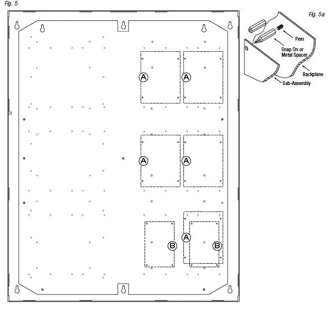
- Fasten snap on spacers onto metal pems configuration (A) (B) of backplane depending on the access controller (Fig. 5, pg. 9).
- Position access controller module over corresponding spacers and depress onto snap on spacers (Fig. 5a, pg. 9).
- Mount backplane to enclosure with hardware.
Access Controller Position Chart for the Following Models:
| LenelS2 | Mercury (HID) | Pem Mounting | Current Draw |
| LNL-2210 | LP1501 | A | 12VDC 900mA max. |
| LNL-1300e | MR62e | 12VDC 1100mA max. | |
| LNL-1300 | MR50 | B | 12-24VDC 150mA max. (12VDC @ 110mA nom., 24VDC @ 60mA nom.) |
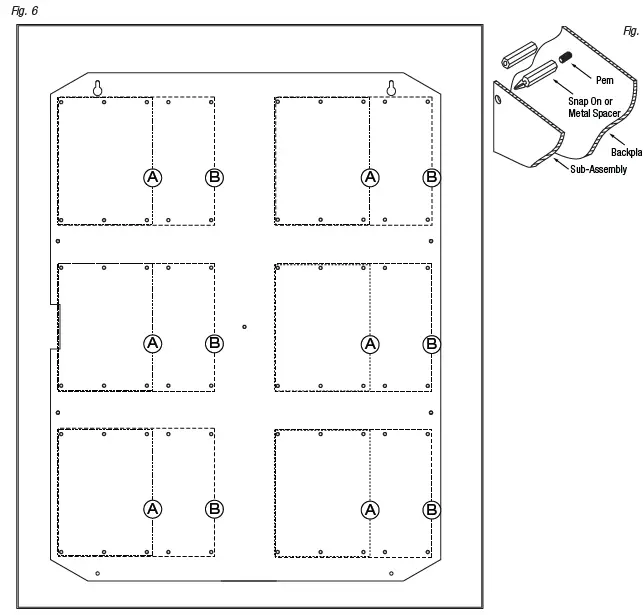
Installation Instructions for Mercury/LenelS2 Access Controllers to TMV2 (Door Backplane):
- Fasten snap on spacers onto metal pems configuration (A) (B) of backplane depending on the access controller (Fig. 6, pg. 10).
- Position access controller module over corresponding spacers and depress onto snap on spacers (Fig. 6a, pg. 10).
- Mount backplane to enclosure with hardware.
| LenelS2 | Mercury (HID) | Pem Mounting | Current Draw |
| LNL-3300 | LP2500 | A | 12-24VDC 300mA max. |
| LNL-8000 | MUX8 | 12VDC 250mA max. | |
| LNL-2220 | LP1502 |
B | 12-24VDC 500mA max. |
| LNL-4420 | LP4502 | 12-24VDC 500mA max. | |
| LNL-1100 | MR16IN | 12-24VDC 350mA max. (12VDC @ 300mA nom., 24VDC @ 220mA nom.) | |
| LNL-1200 | MR16OUT | 12-24VDC 1100mA max. (12VDC @ 850mA nom., 24VDC @ 450mA nom.) | |
| LNL-1320 | MR52 | 12-24VDC 550mA max. (12VDC @ 450mA nom., 24VDC @ 270mA nom.) |
TM3 Sub-Assembly Position Chart for the Following Models:
| Altronix Power Supplies/Chargers | ||||
| Altronix | Pem Mounting | Input Rating | Output Rating | Refer to |
| AL400ULXB2 |
A | 115VAC, 60Hz, 3.5A | 12VDC @ 4A or 24VDC @ 3A | ULXB Installation Instructions Rev. ULXB-020419 |
| AL600ULXB | 115VAC, 60Hz, 3.5A | 12VDC or 24VDC @ 6A | ULXB Installation Instructions Rev. ULXB-020419 | |
| AL1012ULXB | 115VAC, 60Hz, 2.6A | 12VDC @ 10A | ULXB Installation Instructions Rev. ULXB-020419 | |
| AL1024ULXB2 | 115VAC, 60Hz, 4.2A | 24VDC @ 10A | ULXB Installation Instructions Rev. ULXB-020419 | |
| eFlow4NB* | 120VAC, 60Hz, 3.5A | 12VDC or 24VDC @ 4A | eFlow Installation Instructions Rev. EFNB-021319 | |
| eFlow6NB* | 120VAC, 60Hz, 3.5A | 12VDC or 24VDC @ 6A | eFlow Installation Instructions Rev. EFNB-021319 | |
| eFlow102NB* | 120VAC, 60Hz, 3.5A | 12VDC @ 10A | eFlow Installation Instructions Rev. EFNB-021319 | |
| eFlow104NB* | 120VAC, 60Hz, 4.5A | 24VDC @ 10A | eFlow Installation Instructions Rev. EFNB-021319 | |
| Altronix Sub-Assemblies | ||||
| Altronix | Pem Mounting | Current Draw | Refer to | |
| ACM4(CB) |
B | 12VDC @ 0.4A max. or 24VDC @ 0.2A max. | ACM4/ACM4CB Installation Instructions Rev. 052819 | |
| ACM8(CB) | 12VDC @ 0.5A max. or 24VDC @ 0.3A max. | ACM8/ACM8CB Installation Instructions Rev. 031819 | ||
| MOM5 | 12-24VDC 55mA max. | MOM5 Installation Instructions Rev. 020119 | ||
| PD4UL(CB) | N/A | PD4UL Installation Instructions Rev. 020119 | ||
| PD4ULCB Installation Instructions Rev. 020119 | ||||
| PD8UL(CB) | N/A | PD8UL Installation Instructions Rev. 020119 | ||
| PD8ULCB Installation Instructions Rev. 020119 | ||||
| PD16W(CB) | N/A | PD16W/PD16WCB Installation Instructions Rev. 020119 | ||
| PDS8(CB) | N/A | PDS8/PDS8CB Installation Instructions Rev. 070116 | ||
| VR6 | 24VDC @ 1.75A or 3.5A (Output: 5VDC or 12VDC @ 6A) | VR6 Installation Instructions Rev. 050517 | ||
| LINQ2* | C | 12-24VDC 100mA max. | LINQ2 Installation Instructions Rev. 060514 | |
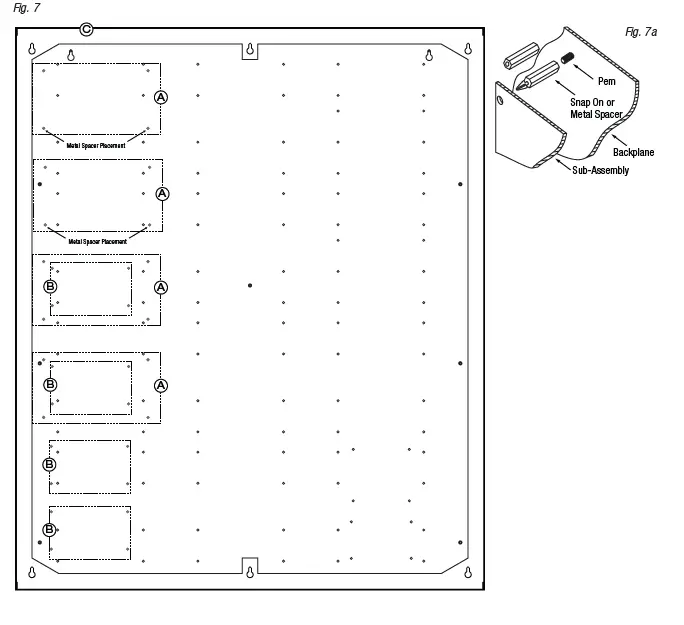
Installation Instructions for Altronix Power Supplies and/or Sub-Assemblies to TM3:
- Fasten spacers (provided) to pems that match the hole pattern for Altronix Power Supply/Chargers or Altronix Sub-Assembly boards (Fig. 7, pg. 12). Use snap on nylon spacers for the upper two mounting holes in the board.Use metal spacers for the bottom mounting holes to provide sufficient grounding for the board.
- Affix boards to spacers (Fig. 7a, pg. 12) by pressing down the upper mounting holes onto nylon spacers.
Use provided mounting screws to affix the lower mounting holes. Make sure that boards are locked onto spacers. - For detailed information about installing and connecting Altronix sub-assemblies refer to the individual Installation Instructions listed in the Sub-Assembly Position Chart, pg. 11 and Trove Installation Guide, Rev. 101817.
4. Fasten backplane to Trove3 enclosure utilizing lock nuts (provided).
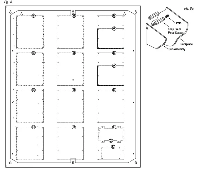
Installation Instructions for Mercury/LenelS2 Access Controllers to TM3:
- Fasten snap on spacers onto metal pems configuration (A) (B) of backplane depending on the access controller (Fig. 8, pg. 13).
- Position access controller module over corresponding spacers and depress onto snap on spacers (Fig. 8a, pg. 13).
- Mount backplane to enclosure with hardware.
| LenelS2 | Mercury (HID) | Pem Mounting | Current Draw |
| LNL-3300 | LP2500 | A | 12-24VDC 300mA max. |
| LNL-8000 | MUX8 | 12VDC 250mA max. | |
| LNL-2220 | LP1502 |
B | 12-24VDC 500mA max. |
| LNL-4420 | LP4502 | 12-24VDC 500mA max. | |
| LNL-1100 | MR16IN | 12-24VDC 350mA max. (12VDC @ 300mA nom., 24VDC @ 220mA nom.) | |
| LNL-1200 | MR16OUT | 12-24VDC 1100mA max. (12VDC @ 850mA nom., 24VDC @ 450mA nom.) | |
| LNL-1320 | MR52 | 12-24VDC 550mA max. (12VDC @ 450mA nom., 24VDC @ 270mA nom.) | |
| LNL-2210 | LP1501 | C | 12VDC 900mA max. |
| LNL-1300e | MR62e | 12VDC 1100mA max. | |
| LNL-1300 | MR50 | D | 12-24VDC 150mA max. (12VDC/110mA nom., 24VDC/60mA nom.) |
TM1 Dimensions
16.625” x 12.5” x 0.3125” (422.3mm x 317.5mm x 7.9mm)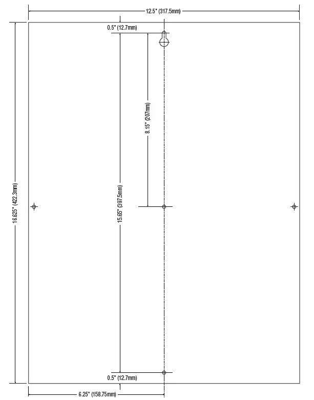
Trove1M1 Enclosure Dimensions (H x W x D approximate): 18” x 14.5” x 4.625” (457mm x 368mm x 118mm)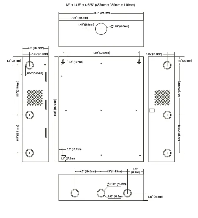
TM2 Dimensions
25.375” x 19.375” x 0.3125” (644.5mm x 482.6mm x 7.9mm).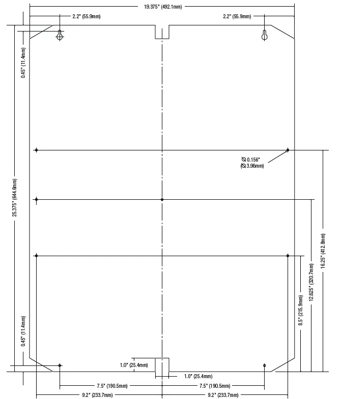
Trove2M2 Enclosure Dimensions (H x W x D approximate): 27.25” x 21.75” x 6.5” (692.2mm x 552.5mm x 165.1mm)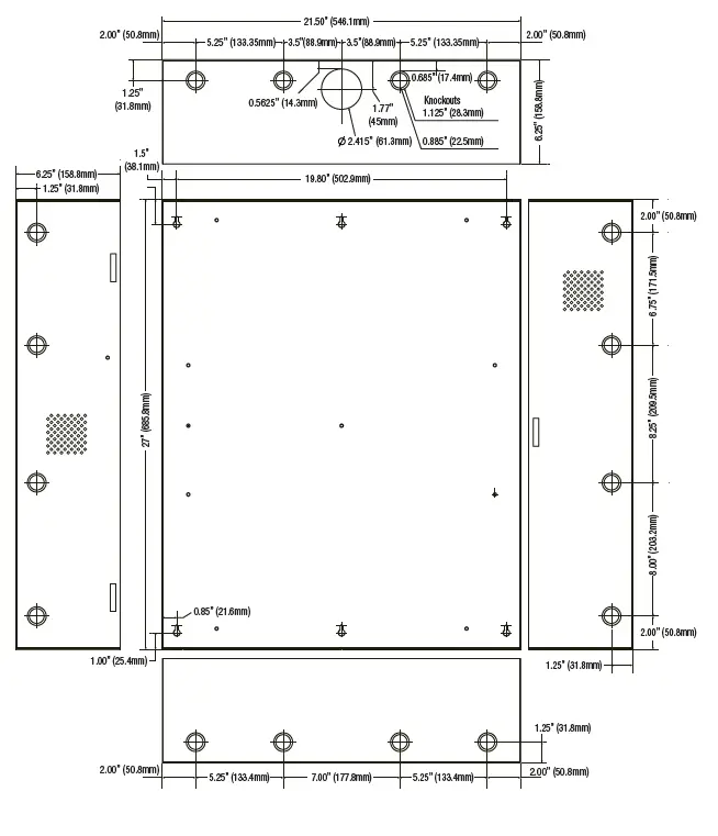
Trove2M2 Enclosure Dimensions (H x W x D approximate): 27.25” x 21.75” x 6.5” (692.2mm x 552.5mm x 165.1mm)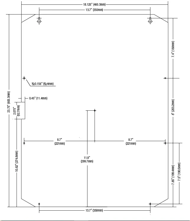
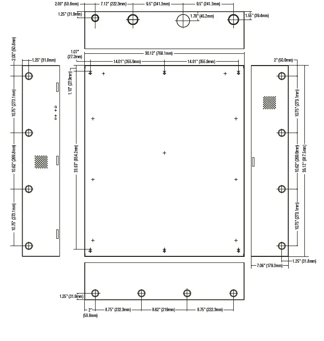
TM3 Dimensions
34” x 28” x 0.3125” (863.6mm x 711.2mm x 7.9mm)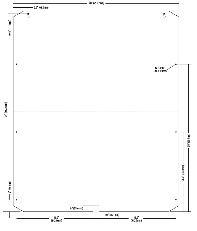
Trove3M3 Enclosure Dimensions (H x W x D approximate): 36.12” x 30.125” x 7.06” (917.5mm x 768.1mm x 179.3mm)