![]()
![]() Access & Power Integration
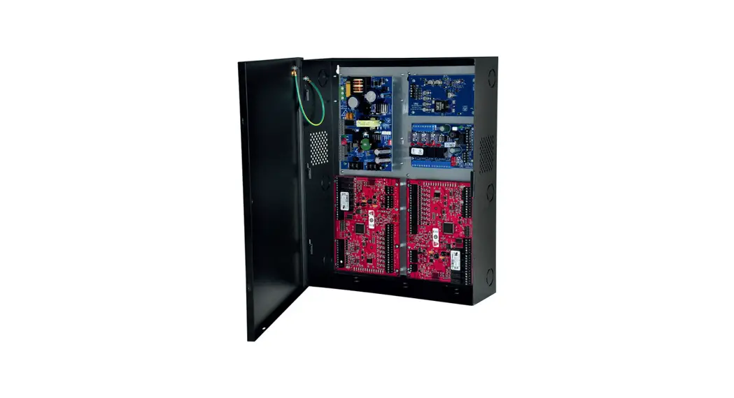
Access & Power Integration
Installation Guide
Altronix/Trove1 Mercury Kits
Models Include:
T1MK14
4 Door Kit with Fused Outputs
Fully assembled kit includes:
– Trove1 enclosure with TM1 Altronix/Mercury backplane
– (1) AL400ULXB2 – Power Supply/Charger
– (1) VR6 – Voltage Regulator
– (1) ACM4 – Fused Access Power Controller
T1MK14S
4 Door Kit with Fused Outputs
Fully assembled kit includes:
– Trove1 enclosure with TM1 Altronix/Mercury backplane
– (1) AL400ULXB2 – Power Supply/Charger
– (1) VR6 – Voltage Regulator
– (1) ACM4 – Fused Access Power Controller
– (1) PDS8 – Dual Input Power Distribution Module
T1MK14D
4 Door Kit with PTC Outputs
Fully assembled kit includes:
– Trove1 enclosure with TM1 Altronix/Mercury backplane
– (1) AL400ULXB2 – Power Supply/Charger
– (1) VR6 – Voltage Regulator
– (1) ACM4CB – PTC Access Power Controller
T1MK14SD
4 Door Kit with PTC Outputs
Fully assembled kit includes:
– Trove1 enclosure with TM1 Altronix/Mercury backplane
– (1) AL400ULXB2 – Power Supply/Charger
– (1) VR6 – Voltage Regulator
– (1) ACM4CB – PTC Access Power Controller
– (1) PDS8CB – Dual Input Power Distribution Module
All components of these Trove kits are UL Listed sub-assemblies.
Please refer to the included corresponding Sub-Assembly Installation Guides for further information.
Rev. T1MKL113021
Installing Company: _________________________ Service Rep. Name: _________________________________________
Address: _________________________________________________________ Phone #: _________________________
Overview:
Altronix Trove Mercury kits are pre-assembled and consist of Trove1M1 enclosure/backplane with factory installed Altronix power supply/charger and sub-assemblies. These kits also accommodate various combinations of Mercury boards for up to four (4) doors in a single enclosure.
Configuration Chart:
| T1MK14SD | T1MK14S | T1MK140 | T1MK14 | Altronix Model Number | |
| 3.0 | 3.0 | 3.0 | 3.0 | 115VAC 60Hz Input Current (A) | |
| 5A/250V | 5A/250V | 5A/250V | 5A/250V | Power Supply Board Input Fuse Rating | |
| 15N 32V | 15N 32V | 15N 32V | 15N 32V | Power Supply Board Battery Fuse Rating | |
| 20.28- 26.4 | 20.28- 26.4 | 20.28- 26.4 | 20.28- 26.4 | 24VDC Output Range (V) | Nominal DC Output |
| 24VDC @ 3.6A | 24VDC @ 3.6A | 24VDC @ 3.6A | 24VDC @ 3.6A | Maximum Supply Current for Outputs on Power Supply board and ACM4/ACM4CB Access Power Controller’s outputs (A) | |
| 1 | 4 | I | 4 | Fail-Safe/Fail-Secure or Dry Form “C” Outputs | |
| 4 | 1 | 4 | 1 | Fail-Safe/Fail-Secure Outputs (auto-resettable) | |
| 1 | 3. | 1 | 3. | Current Per ACM4 Output (A) | |
| 2.0 | 1 | 2.0 | 1 | Current Per ACM4CB Output (A) | |
| 10A/250V | 10A/250V | 10A/250V | 10A/250V | ACM4/ACM4CB Board Input Fuse Rating | |
| 1 | 3N 250V | 1 | 3N 250V | ACM4 Board Output Fuse Rating | |
| 2.0A | 1 | 2.0A | 1 | ACM4CB Board Output PTC Rating | |
| 10A/250V | 10A/250V | 1 | 1 | PDSB/PDSBCB Board Input Fuse Rating | |
| 1 | 3N 250V | 1 | 1 | PDSB Board Output Fuse Rating | |
| 2.0A | 1 | 1 | 1 | PDSBCB Board Output PTC Rating | |
Installation Instructions:
Wiring methods shall be in accordance with the National Electrical Code/NFPA 70/ANSI and with all local codes and authorities having jurisdiction.
Product is intended for indoor use only.
- Remove backplane from enclosure. Do not discard hardware.
- Mark and predrill holes in the wall to line up with the top two (2) keyholes in the enclosure. Install two upper fasteners and screws in the wall with the screw heads protruding. Place the enclosure’s upper keyholes over the two upper screws; level and secure.
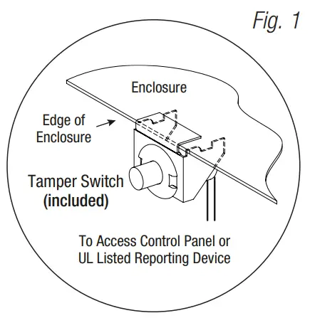
Mark the position of the lower two holes. Remove the enclosure. Drill the lower holes and install the two fasteners. Place the enclosure’s upper keyholes over the three upper screws. Install the two lower screws and make sure to tighten all screws. - Mount included UL Listed tamper switch (Altronix Model T112 or equivalent) in desired location, opposite hinge.
Slide the tamper switch bracket onto the edge of the enclosure approximately 2” from the right side (Fig. 1, pg. 2).
Connect tamper switch wiring to the Access Control Panel input or the appropriate UL Listed reporting device.
To activate alarm signal open the door of the enclosure. - Position Mercury access controller modules over corresponding spacers and depress onto snap on spacers, Fig. 2, 3, pg. 3, 4.
- Refer to the ULXB Power Supply/Charger Installation Guide for AL400ULXB2, and corresponding Sub-Assembly Installation Guide for ACM4(CB), PDS8(CB) and VR6 for further installation instructions.
- Mount backplane to enclosure with hardware.
Hardware:
| Snap On Spacer | |
 | 5/16” Pan Head Screw |
 | Lock Nut |
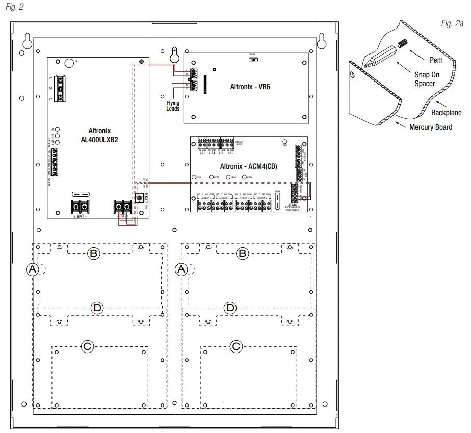
T1MK14 and T1MK14D: Configuration of Mercury Boards:
- Fasten snap on spacers onto metal pems configuration (A), (B), (C) or (D) of backplane depending on the access controller (Fig. 2, pg. 3).
- Position access controller module over corresponding spacers and depress onto snap on spacers (Fig. 2a, pg. 3).
- Mount backplane to enclosure with hardware.
Access Controller Position Chart for the Following Models:
| Mercury Access Controller | Pem Mounting |
| EP1502, LP1502, MR52, MR16IN, MR16OUT | A |
| EP1501, LP1501, MR51e, MR62e | B |
| MR50 | C |
| EP2500, LP2500, MUX8 | D |
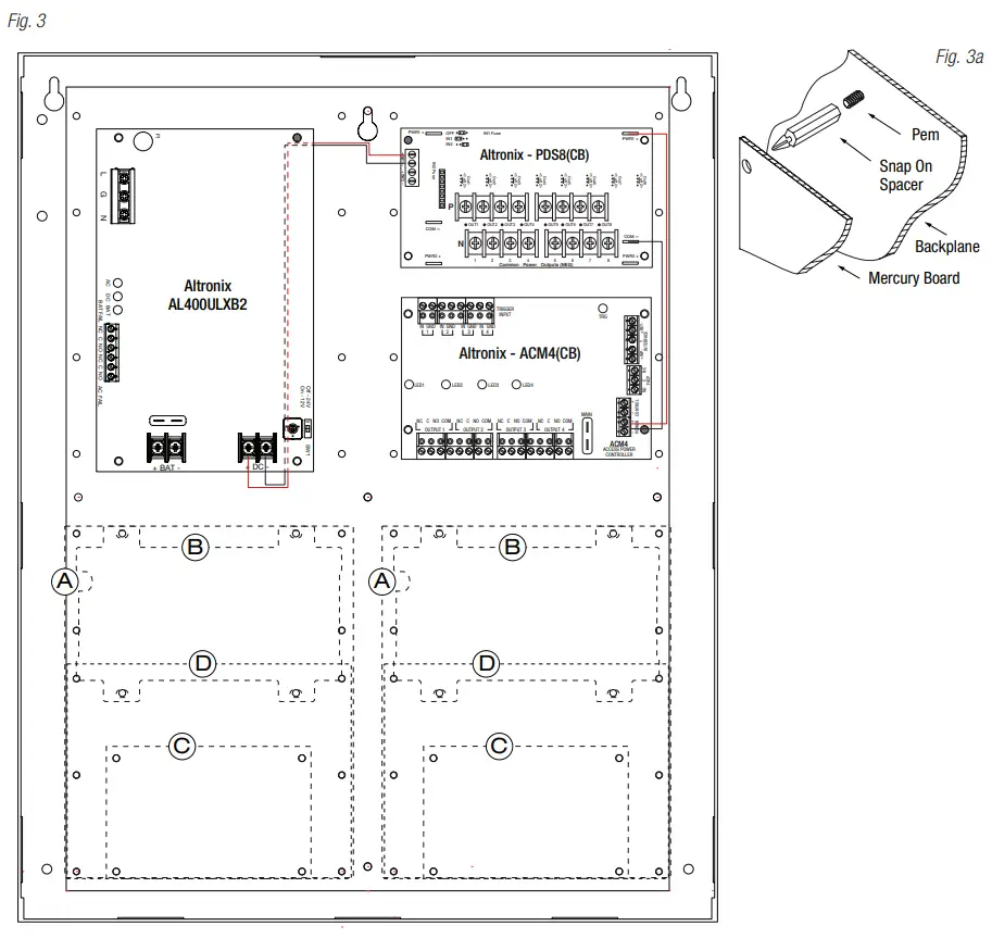
T1MK14S and T1MK14SD: Configuration of Mercury Boards:
- Fasten snap on spacers onto metal pems configuration (A), (B), (C) or (D) of backplane depending on the access controller (Fig. 3, pg. 4).
- Position access controller module over corresponding spacers and depress onto snap on spacers (Fig. 3a, pg. 4).
- Mount backplane to enclosure with hardware.
Access Controller Position Chart for the Following Models:
| Mercury Access Controller | Pem Mounting |
| EP1502, LP1502, MR52, MR16IN, MR16OUT | A |
| EP1501, LP1501, MR51e, MR62e | B |
| MR50 | C |
| EP2500, LP2500, MUX8 | D |
Notes:
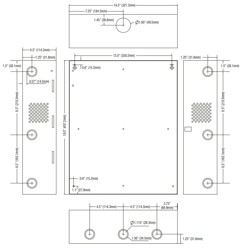
Trove1 Enclosure Dimensions (H x W x D approximate):
18” x 14.5” x 4.625” (457mm x 368mm x 118mm)
 Altronix is not responsible for any typographical errors.
140 58th Street, Brooklyn, New York 11220 USA | phone: 718-567-8181 | fax: 718-567-9056
web site: www.altronix.com | e-mail: [email protected] | Lifetime Warranty
IITrove1M1 ULXB Kit Series
K30U
Trove1 Mercury ULXB Kits Installation Guide


