![]() NetWay2ES Series PoE-Powered 2-Port PoE+ Switches
NetWay2ES Series PoE-Powered 2-Port PoE+ Switches
Installation Guide
NetWay2ES Series
PoE-Powered 2-Port PoE+ Switches
Models Include:
NetWay2ES
- 2-Port PoE+ Switch
- Modular plastic case.
NetWay2ESWPN
- 2-Port PoE+ Switch
- NEMA4/4X rated outdoor enclosure.
Installing Company: ____________Service Rep. Name: ___________
Address: _______________ Phone #: ________
Overview:
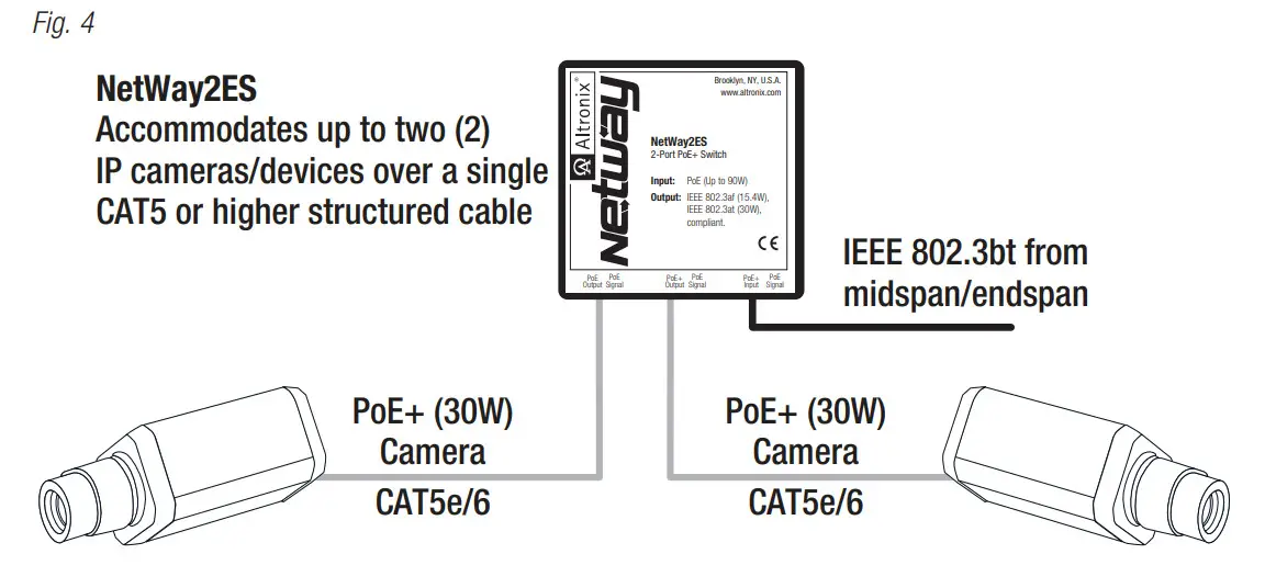
Altronix NetWay2ES and NetWay2ESWPN are PoE-powered 2-port PoE/PoE+ switches accommodating up to two (2) IP cameras/devices over a single CAT5 or higher structured cable. PoE is passed from a midspan injector, typically located at the MDF (Main Distribution Frame).
Features:
Agency Listings:
- CE European Conformity.
Ethernet Input:
- 802.3bt PoE up to 90W or 802.3at up to 30W or
802.3af up to 15W is provided by
PoE midspan/endspan. - IEEE 802.3bt compliant.
Output:
- IEEE 802.3af (15.4W),
IEEE 802.3at (30W) compliant.
Ports:
- Connectivity: RJ45, auto-crossover.
- Wire type: 4-pair CAT5e and higher.
- Speed: 10/100 Mbps.
- Distance: up to 100m.
Environmental:
- Refer to Environmental Conditions on page 5.
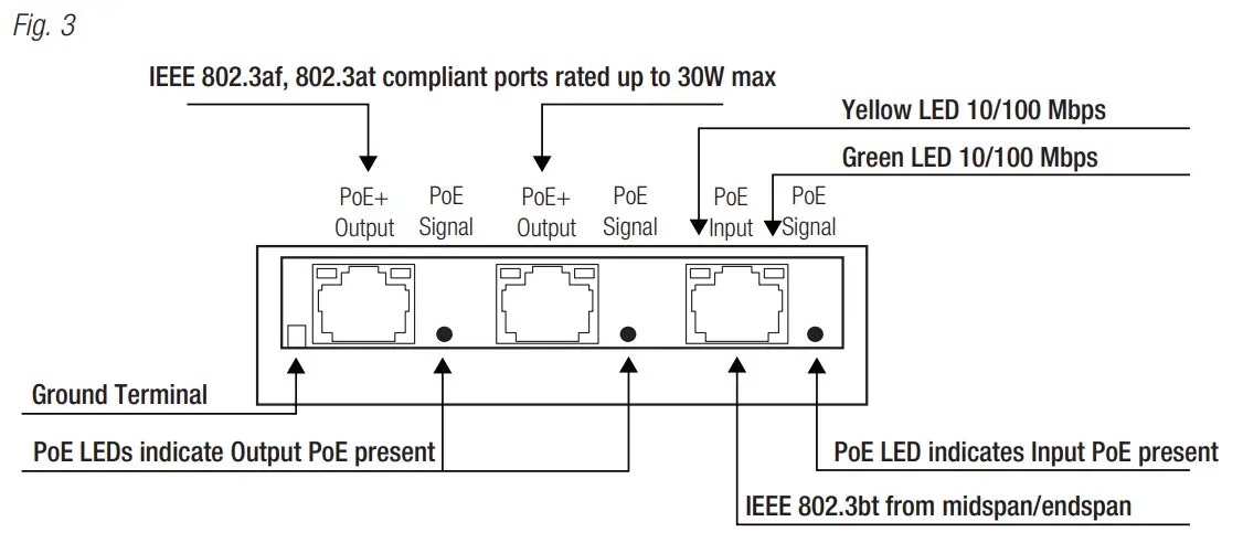
LED Indicators (Refer to Fig. 3, Pg. 4): - Yellow and Green LEDs (RJ45 jacks):
IP Link status, 10/100Base-T/active. - Green PoE LEDs:
Indicate PoE present.
Mechanical:
NetWay2ES:
- Modular plastic case.
3.375” x 3.8” x 1” (85.7mm x 96.5mm x 25.4mm).
NetWay2ESWPN:
- NEMA4/4X, IP66 Rated enclosure for outdoor use.
- Dimensions (H x W x D approx.): 9.5” x 7.32” x 4.92” (241.3mm x 185.9mm x 125mm)
Installation Instructions:
Wiring methods shall be in accordance with the National Electrical Code/NFPA 70/ANSI, and with all local codes and authorities having jurisdiction. All units should be installed by a trained service personnel.
Installation:
NetWay2ES:
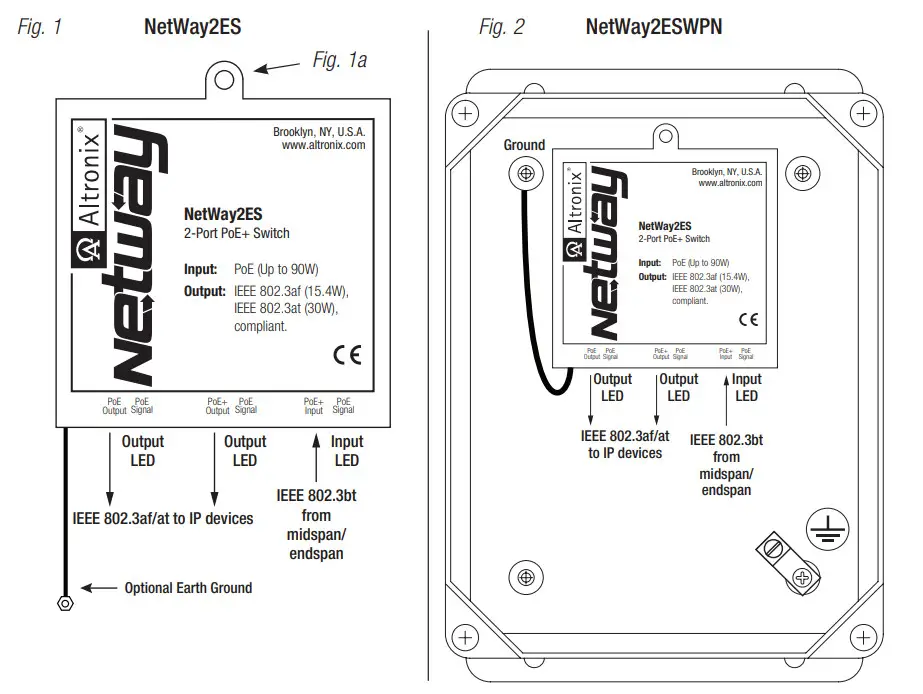
- Mount NetWay2ES in desired location utilizing the mounting hole (Fig. 1a, pg. 4). Use a proper fastener and/or wall anchor when securing NetWay2ES with screw through its mounting hole to the surface.
Note: Earth ground can be used, if needed, for high transient or outdoor environments. If used, insert an Earth ground wire (included with product) into the internal ground terminal until secured (a slight tug can check stability) & fasten the free end to a chassis earth ground (Fig. 3, pg. 4).
NetWay2ESWPN: - Remove backplane from enclosure prior to drilling. Do not discard hardware.
Note: Make sure that hardware will not interfere with components of the circuit board. - Mark and drill desired inlets on the enclosure to facilitate wiring. Maximum NEMA type 4X rated fittings to be used are 0.5”. Follow manufacturer’s specifications for the appropriate size opening.
Note: Inlets for conduit fittings should only be made on the bottom of the enclosure.
To facilitate wire entry utilize weather-tight NEMA rated connectors (supplied), bushings, and cable. - Clean out the inside of enclosure before remounting circuit boards/backplane.
- Mounting NEMA4/4X rated enclosure (Enclosure Dimensions, pg. 7):
Wall mount:
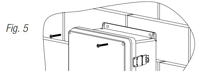
Mount unit in desired location. Mark and drill holes to line up with the top and bottom hole of the enclosure flange. Secure enclosure with appropriate fasteners (e. g. screws and anchors; bolts and locking nuts, etc.) that are compatible with mounting surface and are of sufficient length/construction to ensure a secure mount (Fig. 5, pg. 6).
Pole Mount:
Refer to Fig. 6 – 10, pg. 6. - Mount backplane in enclosure with hardware.
Input/Data Connections:
Unit is powered via CAT5e by midspan or endspan. NetWay2ES is not intended to be connected to outside plant leads and should be installed indoors within the protected premises.
- Connect structured cable from port marked [PoE Input] on NetWay2ES to a PoE midspan/endspan (Fig. 3, pg. 5).
- Using 4-pair CAT5e or higher cable connect PoE load devices to be powered to the ports marked [PoE+ Output] on NetWay2ES (Fig. 3, pg. 5). After authentication and classification have been established, [PoE Signal] LEDs will illuminate indicating PoE presence.
Typical Application:
Technical Specifications:
| Parameter | Description | |
| Ports | One (1) IEEE 802.3bt compliant input port rated up to 90W max. Two (2) IEEE 802.3af, 802.3at compliant output ports rated up to 30W max. | |
| Input Power Requirements | IEEE 802.3bt compliant midspan/endspan. | |
| Indicators | Yellow and Green LEDs (RJ45 jacks): IP Link status, 10/100 Base-T/active. PoE Green LED: Indicates PoE present. | |
| Evironmental Conditions | Temperature: NetWay2ES: Operating: Storage: NetWay2ESWPN: Operating: Storage: Relative Humidity: Operating Altitude: | – 40°C to 75°C (— 40°F to 167°F). – 40°C to 75°C (— 40°F to 167°F). – 40°C to 75°C (— 40°F to 167°F). – 40°C to 85°C (— 40°F to 185°F). 85% +/-5%. — 304.8 to 2,000m. |
| Regulatory Compliance | ||
| Weights (approx.) | NetWay2ES: NetWay2ESWPN: | Product: 0.25 lb. (0.11 kg) I Shipping: 0.42 lb. (0.19 kg). Product: 3.7 lb. (1.68 kg) I Shipping: 5 lb. (2.27 kg). |
Wall Mount Installation:
- Place unit at desired location and secure with mounting screws (not included) (Fig. 5, pg. 6).

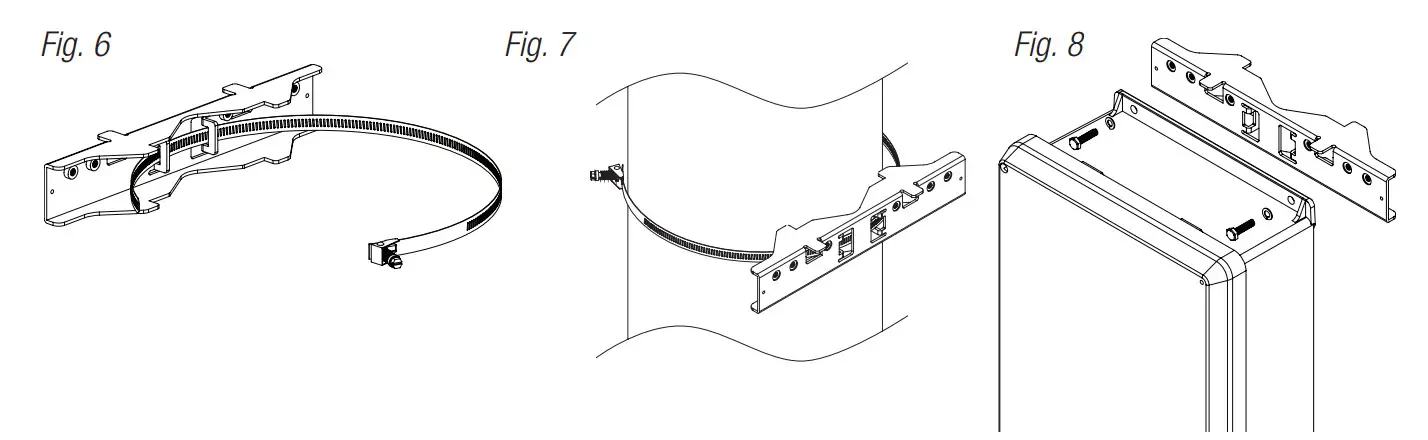
Pole Mounting Using Optional Pole Mount Kit PMK1:
This installation should be made by qualified service personnel. This product contains no serviceable parts. PMK1 outdoor pole mount kits is designed to simplify the installation of Altronix outdoor rated power supplies and accessories housed in models WP1, WP3 and WP4 NEMA rated enclosures. PMK1 can be mounted on 2” to 8” (50.8mm to 203.2mm) diameter round or 5” (127mm) square poles. Brackets are designed for use with the Wormgear Quick Release Straps (two included).
- Thread one (1) wormgear quick release strap through the slots on the back of a mounting bracket (Fig. 6, pg. 6).
- Once the desired height of the top Pole Mount bracket is achieved, tighten the straps down by sliding open end of the strap through the locking mechanism on the strap, then tighten the screw with flat head screwdriver or 5/16” hex socket driver (Fig. 7, pg. 6 and Fig. 9, pg. 6).

- Attach the bottom bracket to the enclosure by inserting bolts through the flange of the enclosure and into the bracket, tightening bolts with a 7/16” hex socket (Fig. 8, pg. 6).
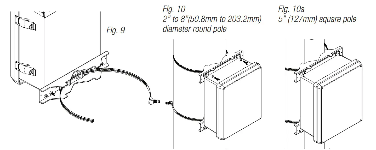
- Thread the second wormgear quick release strap through the slots on the back of the bottom mounting bracket (Fig. 9, pg. 6).
- Mount enclosure onto the top bracket by inserting bolts through flange of the enclosure and into the bracket, tightening bolts with a 7/16” hex socket (Fig. 8, pg. 6).
- Tighten the straps of the bottom bracket down by sliding the open end of the strap through the locking mechanism on the strap, then tighten screw with flat head screwdriver or 5/16” hex socket driver (Fig. 7, 9, pg. 6).
- Clip excess straps.
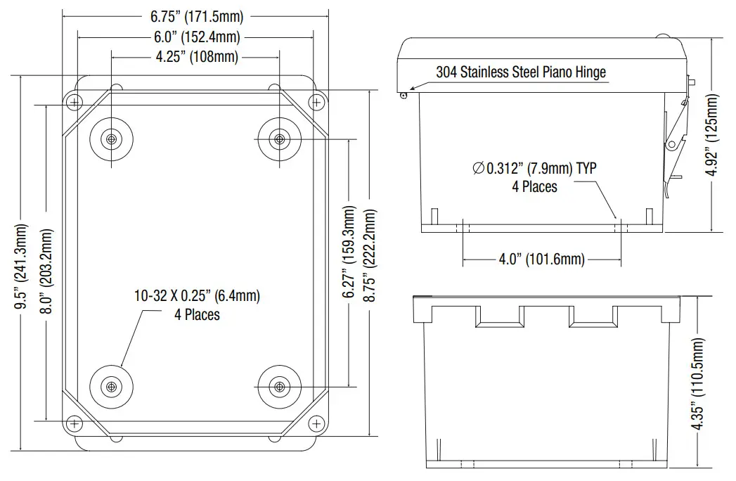
NetWay2ESWPN
Mechanical Drawing and Dimensions (H x W x D approx.):
9.5” x 7.32” x 4.92” (241.3mm x 185.9mm x 125mm)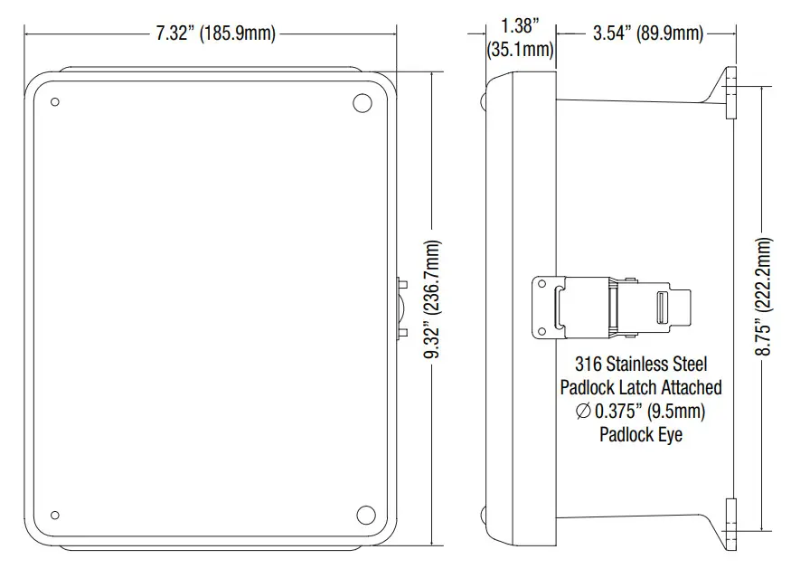
Notes:
Altronix is not responsible for any typographical errors.
140 58th Street, Brooklyn, New York 11220 USA | 718-567-8181 | fax: 718-567-9056
website: www.altronix.com | e-mail: [email protected] | Lifetime Warranty
IINetWay2ES Series
L28U![]()


