![]()
![]() NetWay112
NetWay112
Single Port PoE Injector for
Standard NetWork Infrastructure
Installation Guide
Overview:
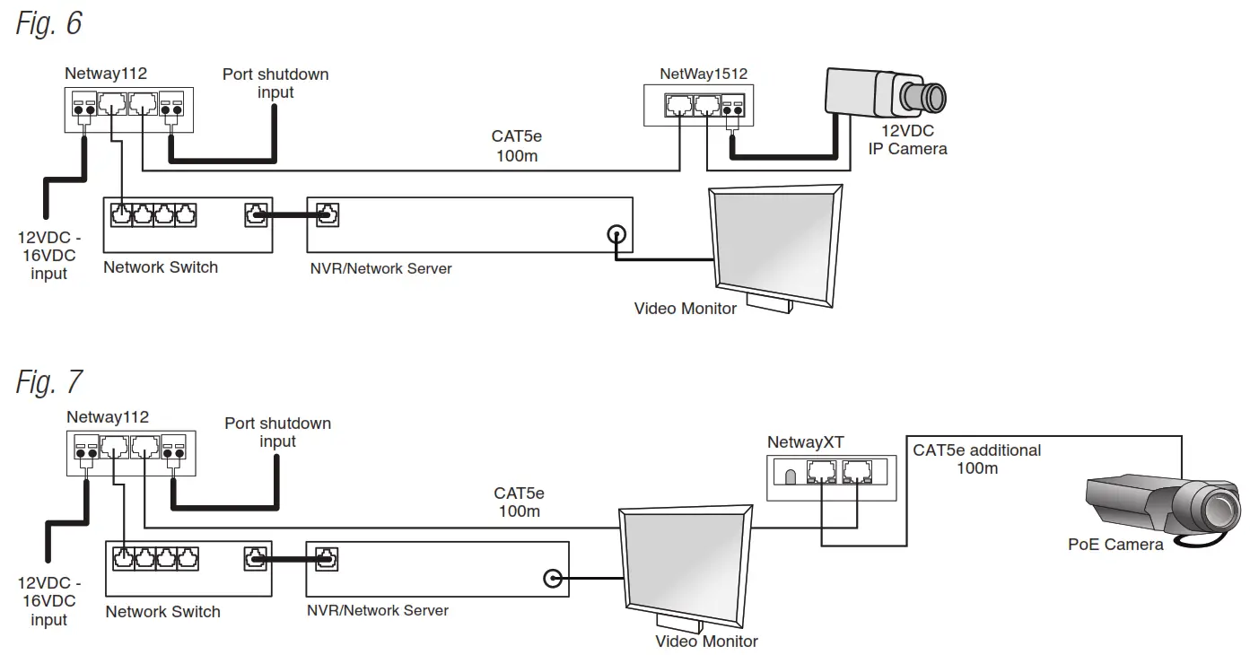
Altronix NetWay112 is a single port PoE injector which provides power and passes data (e.g. video) for PoE compliant devices. Devices may be located up to 100m from NetWay112.
To extend data distance for an additional 100m use NetWayXT/NetWayXTX repeater modules.
Features:
Agency Listings:
- UL 60950-1
Information Technology Equipment. - CE
European Conformity.
Input: - 12VDC/1.5A to 16VDC/1.1A.
Data: - One (1) PoE port provides power and passes data over ethernet (CAT5) cable up to 100m.
- Data rate: 10/100 Base-T compliant.
PoE: - IEEE 802.3af (15W) compliant.
Features:
- Port status LED.
- PoE manual shutdown feature allows for cameras and/or edge devices to be reset.
For UL 60950-1 applications only (see Technical Specifications table pg. 4). - Auto detection and protection of legacy non-PoE cameras/devices.
- Data rate: 10/100 BASE-T compliant.
- Compact insulated housing.
- Spring terminals (Input and PoE shutdown).
Dimensions (W x L x H approx.): 2.5” x 3.8” x 1” (63.5mm x 96.52mm x 25.4mm).
Installation Instructions:
Wiring methods shall be in accordance with the National Electrical Code/NFPA 70/ANSI, and with all local codes and authorities having jurisdiction.
Wiring should be UL Listed and/or Recognized wire suitable for the application.
Unit is intended to be used with a UL Listed Class 2 or LPS (limited power supply). NetWay112 is not intended to be connected to outside plant leads and should be installed indoors within the protected premises. NetWay112 is intended for indoor use only.
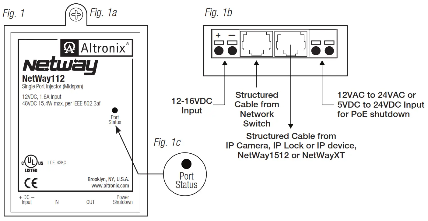
- Mount NetWay112 in desired location utilizing the mounting hole (Fig. 1a, pg. 2). Use a proper fastener and/or wall anchor when securing NetWay112 with screw through its mounting hole to the wall.
- Connect UL Listed Class 2 or LPS (limited power supply) providing 12VDC/1.5A to 16VDC/1.1A to terminals marked [+ DC – Input], carefully observing polarity (Fig. 1b, pg. 2).
Use 22AWG – 16AWG wire for this connection.
Input power should be a Access Control power supply or a transformer. - Connect structured cable from port marked [IN] on NetWay112 to the corresponding input of an UL Listed ethernet switch or video server (Fig. 1b, pg. 2).
- Connect structured cable from port marked [OUT] on the NetWay112 to the PoE device (Fig. 1b, pg. 2).
- Port status LED will illuminate indicating normal operation (Fig. 1c, pg. 2).
- To initiate PoE shutdown connect 12VAC to 24VAC or 5VDC to 24VDC to the input terminals marked [Power Shutdown] on the NetWay112 (Fig. 1b, pg. 2). The PoE output voltage may be shut down by manually applying voltage in the rated range (PoE Shutdown Voltage Range in Specifications). Upon applying voltage, the output will drop to zero volts. Removal of voltage from the shutdown terminals or applying zero volts to the shutdown terminals will allow the PoE output to operate normally to supply power to PoE compliant devices.
Note: Return to normal operation from shutdown can take about 4 seconds. Although there is no output voltage to power PoE devices during shutdown, data signals may still be present on the data pair lines of the CAT5 cable.
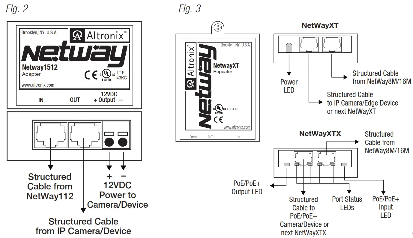
Installing a NetWay1512 adapter for 12VDC IP cameras up to 13W:
- Mount NetWay1512 in the proximity of IP camera (Fig. 2, pg. 3). Use velcro (supplied).
- Connect structured cable from port marked [IN] on NetWay1512 to port marked [OUT] of NetWay112 (Fig. 2, pg. 3, Fig. 1b pg. 2).
- Connect structured cable from port marked [OUT] on NetWay1512 to the IP camera/device (Fig. 2, pg. 3, Fig. 1b pg. 2).
- Connect 12VDC output from NetWay1512 terminals marked [+ 12VDC –] to the power input of the IP camera (Fig. 2, pg. 3). Polarity must be observed.
- Power LED indicator will illuminate on NetWay1512 under normal conditions (Fig. 2, pg. 3).
NetWay112 Port Status and LED Flash Codes IP Camera, IP Lock or IP device,
| Port Status | Flash Code | Flash Pattern |
| Non-Powered Device 0Ω < RPORT < 200Ω | OFF | LED OFF |
| Port Open RPORT > 1MΩ | OFF | LED OFF |
| Port On 25kΩ | ON | LED ON |
| Low Signature Resistance 300Ω < RPORT < 15kΩ | 1 Flash | |
| High Signature Resistance 33KΩ < RPORT < 500kΩ | 2 Flashes | |
| Port Overload Fault | 5 Flashes |
Installing a NetWayXT/NetWayXTX repeater module:
NetWayXT will work only with PoE devices. NetWayXTX will work with PoE/PoE+ devices.
- Mount NetWayXT/NetWayXTX in desired location utilizing the mounting hole (Fig. 3, pg. 3).
Use a proper fastener and/or wall anchor when securing NetWayXT/NetWayXTX to the wall. - Connect structured cable from port marked [OUT] on NetWay112 to port marked [IN] on the NetWayXT/NetWayXTX (Fig. 3, pg. 3, Fig. 1b, pg. 3).
- Connect structured cable from port marked [OUT] on NetWayXT/NetWayXTX to the PoE camera/edge device or next NetWayXT/NetWayXTX repeater (Fig. 3, pg. 3).
- Port status LEDs will illuminate on NetWayXT/NetWayXTX indicating the port is operational (Fig. 3, pg. 3, refer to Port LED definitions on pg. 2).
- Power LED will illuminate indicating 12VDC output.
Port LED definitions for NetWayXT repeater:
| Status | Green LED | Yellow LED |
| OFF | Indicates it is connected as 10Base-T or no link. | Indicates no link. |
| ON | Indicates it is connected as 100Base-TX. | Indicates a link. |
| Blinking | – | Indicates activity. |
Port LED definitions for NetWayXTX repeater:
| Status | PoE/PoE+ Output LED | PoE/PoE+ Input LED | Yellow LED |
| OFF | No PoE/PoE+ Output | No PoE/PoE+ Input | Indicates no link. |
| ON | Normal PoE/PoE+ Output | PoE/PoE+ Input | Indicates a link. |
| Blinking | – | – | Indicates activity. |
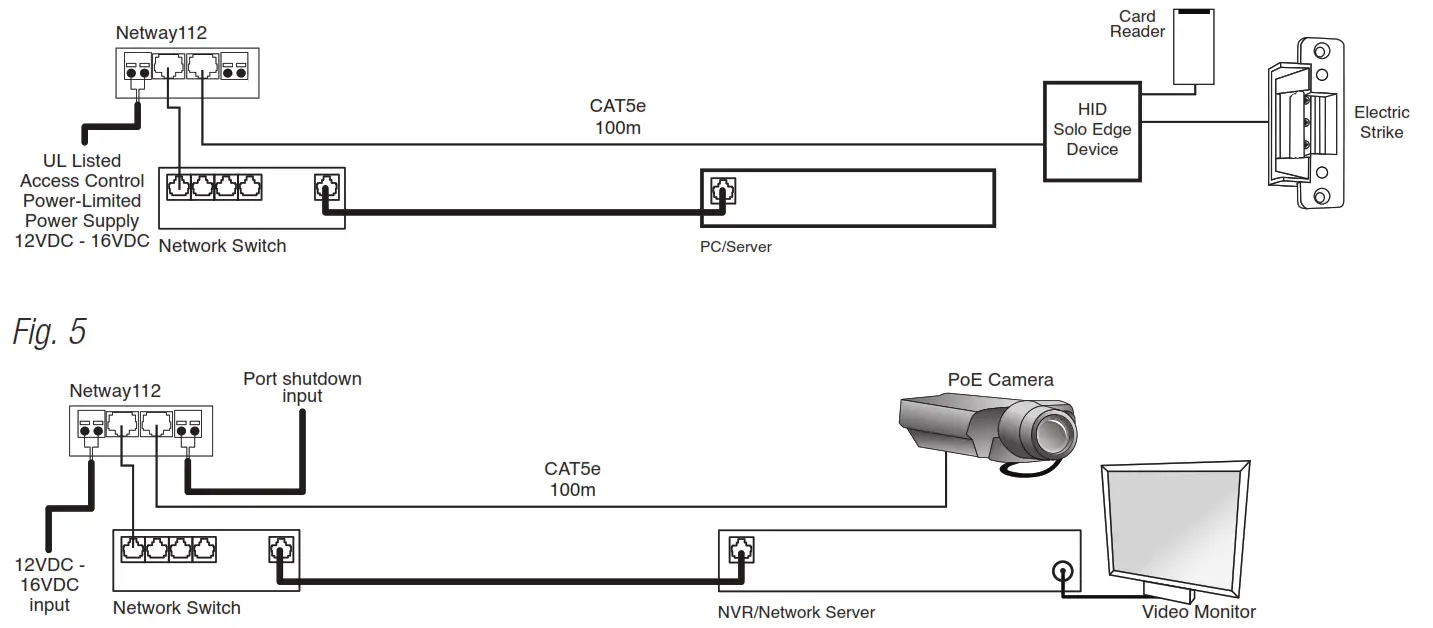
Typical Applications:
Fig. 4 – Typical Access Control application.
Maintenance:
Unit should be tested at least once a year for the proper operation as follows:
While the NetWay112 is powered and the output is connected to a suitable UL Listed PoE device, it should be tested for PoE shutdown operation (For UL 60950-1 applications only).
Troubleshooting:
Refer to NetWay112 Port Status and LED Flash Codes, pg. 2.
Technical Specifications:
| Parameter | Description |
| No. of Ports | One (1) |
| Input power requirements | 12VDC to 16VDC @ 1.5A to 1.1A. |
| Indicators | Port Status LED. |
| PoE Shutdown Voltage and Current Range | 5VDC to 24VDC or 12VAC to 24VAC Maximum current: 2mA for 5VDC Maximum current for higher voltages: 10mA |
| Environmental Conditions | Operating Ambient Temperature (UL60950-1): – 40ºC to 50ºC (– 40º to 122ºF). Relative humidity: 85%, +/ – 5%. Storage Temperature: – 40º to 70ºC (– 40º to 158ºF). Operating Altitude: – 304.8 to 2,000m. |
| Regulatory Compliance | UL/CUL Listed for Information Technology Equipment (UL 60950-1). CE European Conformity. |
| Weights (approx.) | Product: 0.2 lb. (0.1kg) | Shipping: 0.25 lb. (0.11kg). |
Altronix is not responsible for any typographical errors.
140 58th Street, Brooklyn, New York 11220 USA | 718-567-8181 | fax: 718-567-9056
website: www.altronix.com | e-mail: [email protected] | Lifetime Warranty
IINetWay112 Rev. 100614
H19U NetWay112 Installation Guide


