![]()
![]() NetWay V Series
NetWay V Series
PoE Solution for
Standard Network Infrastructure
Models Include:
NetWay8V
– Eight (8) Port PoE Midspan Injector
NetWay16V
– Sixteen (16) Port PoE Midspan Injector
Installation Guide Rev. 071609
Installing Company: _______________ Service Rep. Name: _______________
Address: ___________________ Phone #: ______________
Overview:
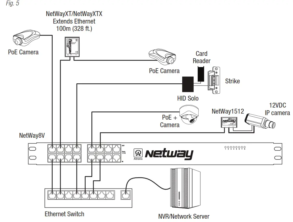
Altronix NetWay8V/NetWay16V Midspans provide power and pass data for PoE-compliant cameras/edge devices.Cameras/edge devices may be located up to 100m from the NetWay unit. A NetWayXT/NetWayXTX repeater module can be utilized to extend the distance an additional 100m for a total range of up to 200m. A maximum range of 600 is possible using multiple repeaters, based on a camera/device port requirements. NetWare Midspans are capable of supporting non-PoE compliant fixed and PTZ IP cameras utilizing NetWay1512 or NetWay3012 adapters.
NetWay Specifications:
NetWay8:
- Eight (8) ports of cameras/edge devices over ethernet (CAT5) cable up to a distance of 100m per port.
- Input: 220VAC 50/60Hz, 1.8A.
NetWay16:
- Sixteen (16) ports of cameras/edge devices over ethernet (CAT5) cable up to a distance of 100m per port.
- Input: 220VAC 50/60Hz, 2.5A
Common Specifications:
Common Specifications: Agency Listings:
- CE European Conformity.
Power:
- Unit supplies PoE output voltage (55V), and up to 30W max. full power per port.
Total power: NetWay8V – 150W, NetWay16V – 300W. - IEEE 802.3af (PoE) and IEEE 802.3at (PoE+) compliant.
- All output circuits are power-limited.
- Short circuit protection.
Functions:
- Auto detection and protection of legacy non-PoE cameras/edge devices.
Features:
- Illuminated master power disconnect circuit breaker with manual reset (switch).
Features (cont’d):
- Individual port status LEDs.
- IEC 320 – 3-wire grounded line cord (detachable).
- Unit can be rack or shelf-mounted.
- 1U rack mount chassis for use in standard EIA 19” rack.
Accessories:
NetWay1512:
- 15W adapter for non-PoE compliant IP cameras.
NetWay3012: - 25W adapter for non-PoE-compliant IP
fixed or PTZ cameras.
NetWayXT: - PoE repeater module extends range 100m.
NetWayXTX: - PoE+ repeater module extends range 100m.
Installation Instructions:
NetWay is not intended to be connected to outside plant leads.
- Attach mounting brackets to NetWay unit for rack installation (Fig. 6, pg. 8).
Affix rubber pads to NetWay for shelf installation (Fig. 8, pg. 7). - Secure the unit in a rack or place the unit on a shelf as desired.
Note: The following factors should be taken into consideration when installing these rack mount units:
a. The unit is to be installed in a space where the maximum ambient temperature does not exceed 104ºF (40ºC).
b. Take care to ensure that there is sufficient airflow around the unit and that obstructions do not impede it.
c. When mounting units in the rack, take care to avoid uneven loading which can cause a hazardous condition. - Set the illuminated master power disconnect circuit breaker to the (OFF) position (Fig. 1d, pg. 3).
- Plug the grounded AC line cord (included) into the IEC 320 connector of the NetWay unit (Fig. 1e, pg. 3).
Plug the unit into the reliable earth-grounded socket. When using multiple units, the sum of the individual nameplate ratings should not exceed the supply circuit rating. Do not connect to a receptacle controlled by a switch. - Connect structured cables from port marked [IN] on NetWay to the corresponding inputs of an ethernet switch or video server (Fig. 1b, pg. 3, Fig. 5, pg. 6).
- Connect structured cables from port marked [OUT] on NetWay to PoE-compliant camera/edge devices (Fig. 1a, pg. 3, Fig. 5, pg. 6).
- Upon completion of the wiring set illuminated master power disconnect circuit breaker to the RESET (ON) position (Fig. 1d, pg. 3).
- Port status LEDs on the NetWay will initialize when PoE devices are connected as follows:
– LED will illuminate when devices are IEEE 802.3af compliant.
– LED will blink once and illuminate when devices are IEEE 802.3at compliant (PoE+).
Port Status and LED Flash Codes:
| Port Status | Flash Codes | Description |
| All Ports Off | Sequential LED Port Scan | No devices connected |
| Port Off | OFF | LED OFF |
| Port On | ON | LED ON |
| Class 4 detection Port | Blinks 2 times | Enables power to PoE devices. |
| Non-compliant Device | 2Hz | Will prevent the port from turning on. |
| Port Overload Fault | 5Hz | Will prevent the port from turning on. |
| 4 Port Overload Grouped | 5Hz | 4 LEDs Will prevent ports from turning on. |
| 8 Port Overload Grouped | 5Hz | LED’s 1-8 Power Supply Overload for ports 1-8. LED’s 9-16 Power Supply Overload for ports 9-16. |
Fig. 1 – NetWay8V/NetWay16V Configuration
NetWay8V – Front Panel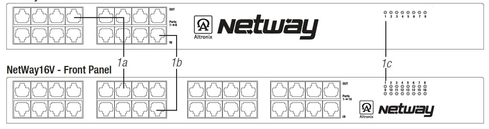
NetWay8V & NetWay16V – Rear Panel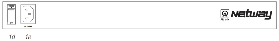
1a OUT 1-8 (NetWay8V), OUT 1-16 (NetWay16V): Structured cable to PoE-compliant cameras/edge devices.
1b IN 1-8 (NetWay8V), IN 1-16 (NetWay16V): Structured cable to an ethernet switch or video server.
1c LED(s) 1-8 (NetWay8V), 1-16 (NetWay16V): Port status LEDs.
1d Illuminated master power disconnect circuit breaker (switch):
- OFF position Circuit breaker tripped. The switch is not illuminated.
- RESET (ON) position. Switch illuminated.
1e IEC 320 Connector: 115VAC 60Hz (grounded line cord included).
Installing a NetWay1512 Adapter for 12VDC IP Cameras up to 13W:
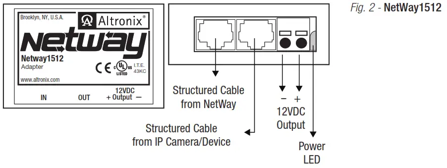
- Mount NetWay1512 in proximity to the IP camera (Fig. 2, pg. 4). Affix one side of velcro (supplied) to NetWay1512 and place the second side of the velcro in the desired location.
- Connect the structured cable from port marked [IN] on NetWay1512 to any ports marked [OUT] of NetWay8/NetWay16 (Fig. 2, pg. 4, Fig. 1a, pg. 3).
- Connect the structured cable from port marked [OUT] on NetWay1512 to the IP camera (Fig. 2, pg. 4).
- Connect 12VDC output from NetWay1512 terminals marked [– 12VDC +] to the power input of the
IP camera (Fig. 2, pg. 4). Polarity must be observed. - The power LED indicator will illuminate on NetWay1512 under normal conditions (Fig. 2, pg. 4).
Installing a NetWay3012 Adapter for 12VDC IP PTZ up to 25W:
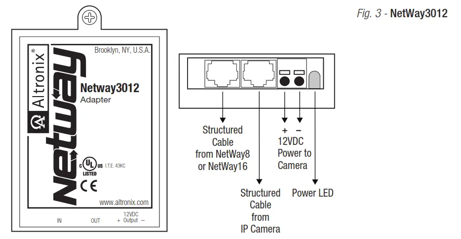
- Mount NetWay3012 in proximity to the IP camera utilizing a mounting hole (Fig. 3, pg. 4). Use a proper fastener and/or wall anchor when securing NetWay3012 to the wall.
- Connect the structured cable from port marked [IN] on NetWay3012 to ports marked [OUT] of NetWay8/NetWay16
(Fig. 3, pg. 4, Fig. 1a, pg. 3). - Connect the structured cable from port marked [OUT] on NetWay3012 to the IP fixed or PTZ camera
(Fig. 3, pg. 4). - Connect 12VDC output from NetWay3012 terminals marked [+ 12VDC – ] to the power input of the
IP camera (Fig. 3, pg. 4). Polarity must be observed. - Power LED indicator will illuminate on NetWay3012 under normal conditions (Fig. 3, pg. 4).
Installing a NetWayXT/NetWayXTX Repeater Module:
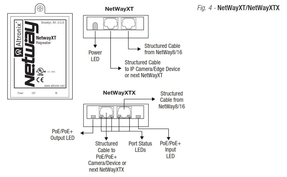
NetWayXT will work only with PoE devices. NetWayXTX will work with PoE/PoE+ devices.
- Mount NetWayXT/NetWayXTX in the desired location utilizing the mounting hole (Fig. 4, pg. 5). Use a proper fastener and/or wall anchor when securing NetWayXT/NetWayXTX to the wall.
- Connect the structured cable from port marked [OUT] on NetWay to port marked [IN] on the NetWayXT/NetWayXTX (Fig. 4, pg. 5, Fig. 1a, pg. 3).
- Connect structured cable from port marked [OUT] on NetWayXT/NetWayXTX to the PoE/PoE+ camera/edge device or next NetWayXT/NetWayXTX repeater (Fig. 4, pg. 5).
- Port status LEDs will illuminate on NetWayXT/NetWayXTX indicating the port is operational (refer to LED Definitions).
- Power LED will illuminate indicating 12VDC output.
Port LED Definitions for NetWayXT Repeater:
| Status | Green LED | Yellow LED |
| OFF | Indicates it is connected as 10Base-T or no link. | Indicates no link. |
| ON | Indicates it is connected as 100Base-TX. | Indicates a link. |
| Blinking | — | Indicates activity. |
Port LED Definitions for NetWayXTX Repeater:
| Status | PoE/PoE+ Output LED | PoE/PoE+ Input LED | Yellow LED |
| OFF | No PoE/PoE+ Output | No PoE/PoE+ Input | Indicates no link. |
| ON | Normal PoE/PoE+ Output | PoE/PoE+ Input | Indicates a link. |
| Blinking | — | — | Indicates activity. |
NetWay8V/NetWay16V Typical Application:
Technical Specifications:
| Parameter | Description |
| No. of Ports | NetWay8V – Eight (8) Ports. NetWayl 6V – Sixteen (16) Ports. |
| Input Power Requirements | NetWay8V: 220VAC, 50/60Hz, 1.8A. NetWayl 6V: 220VAC, 50/60Hz, 2.5A. Fuse: 4A/125V (NetWay16V has 2 fuses). Note: To reduce the risk of fire, replace only with the same type and rating of the fuse. |
| Indicators | Port Status LED |
| Environmental Conditions | Operating Ambient Temperature: -20°C to 40°C (-4°F to 104°F). Relative humidity: 85%, +/- 5%. Storage Temperature: -20° to 70°C (-4° to 158°F). Operating Altitude: -304.8 to 3,048m. |
| Regulatory Compliance | CE European Conformity |
NetWay8V/NetWay16V Rack Mount Chassis
Mechanical Drawing and Dimensions: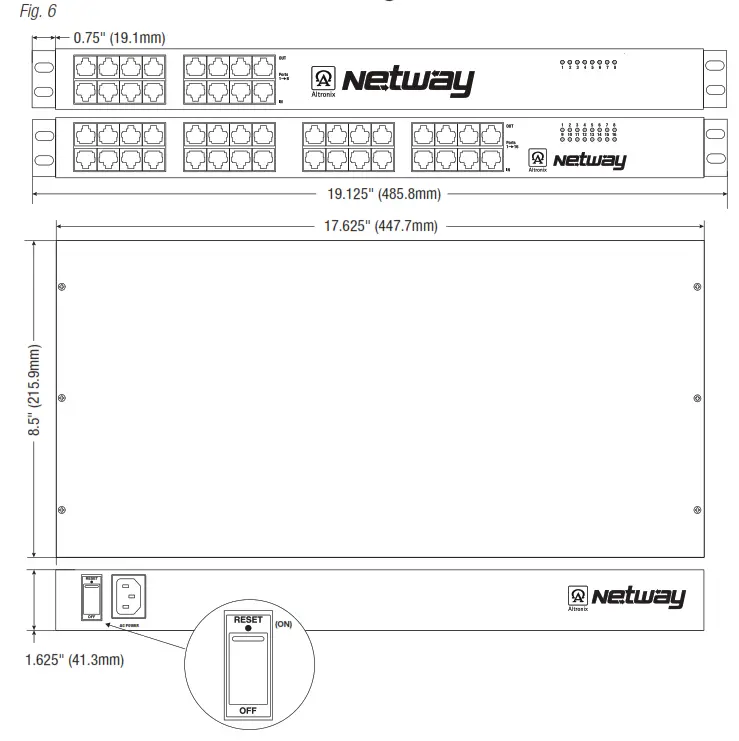
![]() The lightning flash with the arrowhead symbol within an equilateral triangle is intended to alert the user to the presence of an insulated DANGEROUS VOLTAGE within the product’s enclosure that may be of sufficient magnitude to constitute an electric shock.
The lightning flash with the arrowhead symbol within an equilateral triangle is intended to alert the user to the presence of an insulated DANGEROUS VOLTAGE within the product’s enclosure that may be of sufficient magnitude to constitute an electric shock.![]() The exclamation point within an equilateral triangle is intended to alert the user to the presence of important operating and maintenance (servicing) instructions in the literature accompanying the appliance.
The exclamation point within an equilateral triangle is intended to alert the user to the presence of important operating and maintenance (servicing) instructions in the literature accompanying the appliance.![]()

![]() CAUTION: To reduce the risk of electric shock do not open the enclosure.
CAUTION: To reduce the risk of electric shock do not open the enclosure.
There are no user-serviceable parts inside.
Refer servicing to qualified service personnel.
Mounting Options:
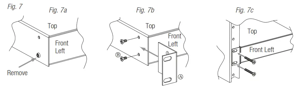
Rack Mount Installation
- Remove and discard factory-installed screws from both sides of the rack chassis (Fig. 7a).
- Install mounting brackets (A) on the left and right side of the rack chassis using the four (4) flat head screws (B) (included) (Fig. 7b).
- Place the unit into desired EIA 19” rack position and secure it with mounting screws (not included) (Fig. 7c).
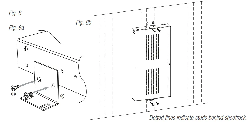
Wall Mount Installation
- Install mounting brackets (A) on the left and right side of the rack chassis using four (4) flathead screws (B) (included) (Fig. 8a).
- Place the unit at the desired location and secure it with #6 size screws or larger (not included) (Fig. 8b).
Caution: It is necessary to make sure mounting screws are securely fastened to a beam when installing the unit vertically.
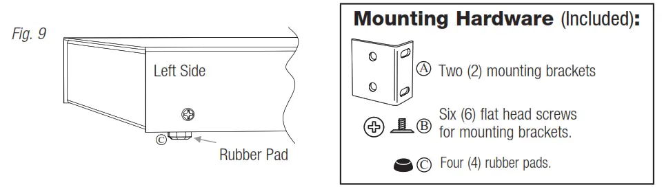
Shelf Installation
- Position and affix rubber pads (C) (included) at each corner on the bottom of the unit (Fig. 9).
- Place the unit in the desired location.
Altronix is not responsible for any typographical errors.
140 58th Street, Brooklyn,
New York 11220 USA
phone: 718-567-8181
fax: 718-567-9056
website: www.altronix.com
e-mail: [email protected]
Lifetime Warranty
Made in U.S.A.
IINetWay8V/NetWay16V H23U