
Altronix AL600ULX Series Power Supply
Overview
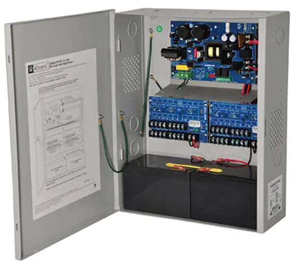
Altronix AL600ULX is a power supply that converts a 115VAC, 60Hz input to a 12VDC or 24VDC regulating output (see specifications below).
The AL600ULX is a base power supply unit for the UL Listed multi-output power supply/charger series: AL600ULPD4, AL600ULPD4CB, AL600ULPD8, AL600ULPD8CB, AL600ULXPD16, AL600ULXPD16CB.
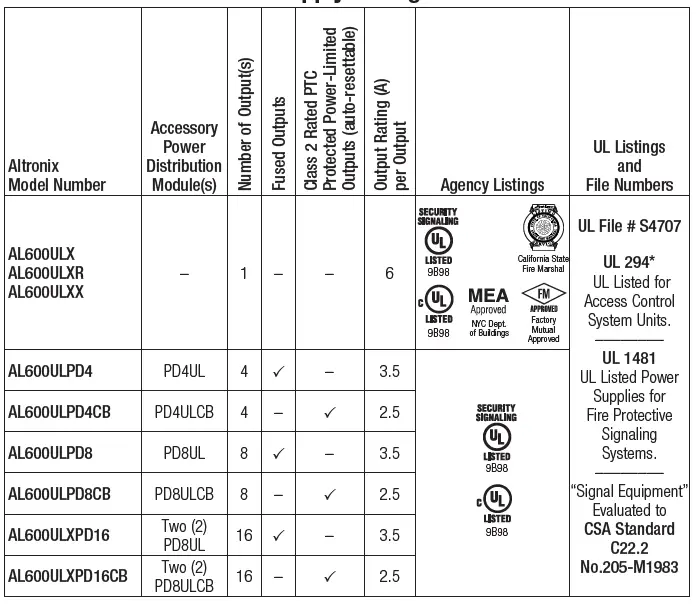
AL600ULX Series Power Supply Configuration Reference Chart
Access Control Performance Levels
- Destructive Attack – I; Endurance – IV; Line Security – I; Stand-by Power – IV.
- Do not exceed total output rating of 6A per unit.
- AL600ULPD4(CB) and AL600ULPD8(CB) are available in larger enclosure.
- Add X to the model number e.g. AL600ULXPD4/CB.
Specifications
Input
Input 115VAC / 60Hz, 3.5A.
Output
- 12VDC or 24VDC selectable output(s).
- 6A continuous supply current at 12VDC or 24VDC.
- Filtered and electronically regulated outputs.
- Short circuit and thermal overload protection.
Battery Backup
- Built in charger for sealed lead acid or gel type batteries.
- Automatic switch over to stand-by battery when AC fails.
- Maximum charge current 0.7A.
- Zero voltage drop when switched over to battery backup.
Supervision
- AC fail supervision form C contacts.
- Low battery supervision form C contacts.
- Battery presence supervision form C contacts.
LED Indicators
AC input, DC output and Battery LED indicators.
Additional Features
- Power supply, enclosure, cam lock and battery leads.
- All models are available in red enclosure add an R suffix.
|
Output Voltage | Voltage Type | Output Current |
Frequency |
Ripple Voltage | |||
| Normal Stand-by | Stand-by Battery Minimum Operating Time | Maximum alarm | Stand-by Battery Minimum Operating Time | ||||
| DC Output 12VDC and 24VDC | DC | See Stand by Specifications | N/A | 300mV | |||
AL600ULX Series
CAUTION
For continued protection against risk of electric shock and fire hazard replace fuse with the same type and rating. Do not expose to rain or moisture.
CAUTION
When power supply board is set for 12VDC use only one (1) 12VDC stand-by battery. Keep power-limited wiring separate from non power-limited. Use minimum 0.25 spacing.
Installation Instructions
Wiring methods shall be in accordance with the National Electrical Code/NFPA 70/NFPA 72/ANSI, and with all local codes and authorities having jurisdiction. Product is intended for indoor use only.
- Mount unit in the desired location.
- Mark and predrill holes in the wall to line up with the top two keyholes in the enclosure.
- Install two upper fasteners and screws in the wall with the screw heads protruding.
- Place the enclosure’s upper keyholes over the two upper screws; level and secure.
- Mark the position of the lower two holes.
- Remove the enclosure.
- Drill the lower holes and install two fasteners.
- Place the enclosure’s upper keyholes over the two upper screws.
- Install the two lower screws and make sure to tighten all screws
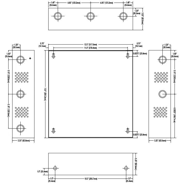
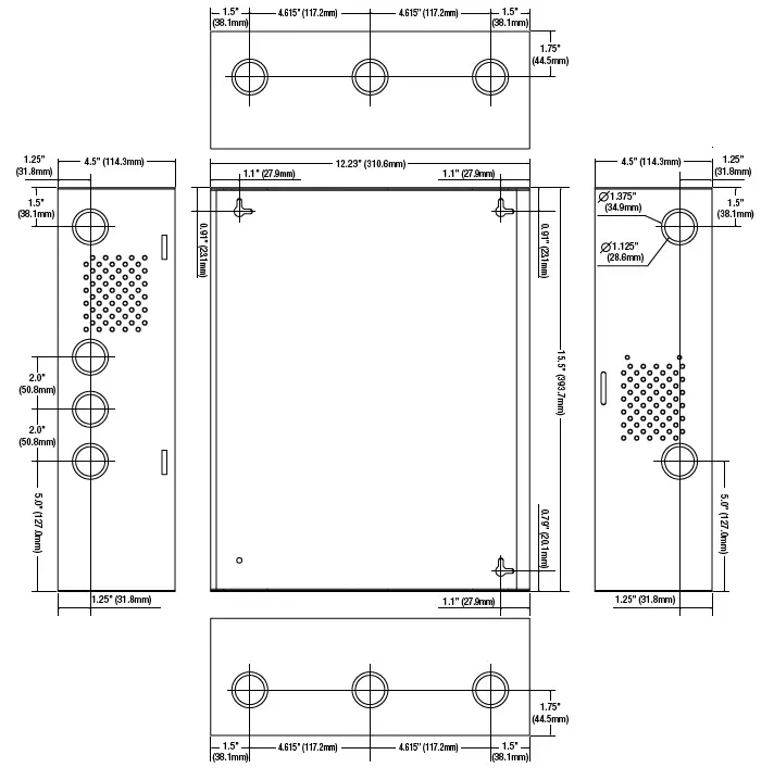
Enclosure Dimensions.
- The power supply is pre wired to the ground chassis.
- Connect main incoming ground to the provided green grounding conductor lead.
- Connect un switched AC power 115VAC, 60Hz to the terminals marked.
- Green AC LED on power supply board will turn on.
- This light can be seen through the LED lens on the door of the enclosure.
- Use 14 AWG or larger for all power connections Battery, DC output, AC input.
- Use 22 AWG to 18 AWG for power limited circuits AC Fail/Low Battery reporting.
- Keep power-limited wiring separate from non power-limited wiring 115VAC, 60Hz Input.
- DC Output, Battery Wires.
- Minimum 0.25 spacing must be provided.
CAUTION
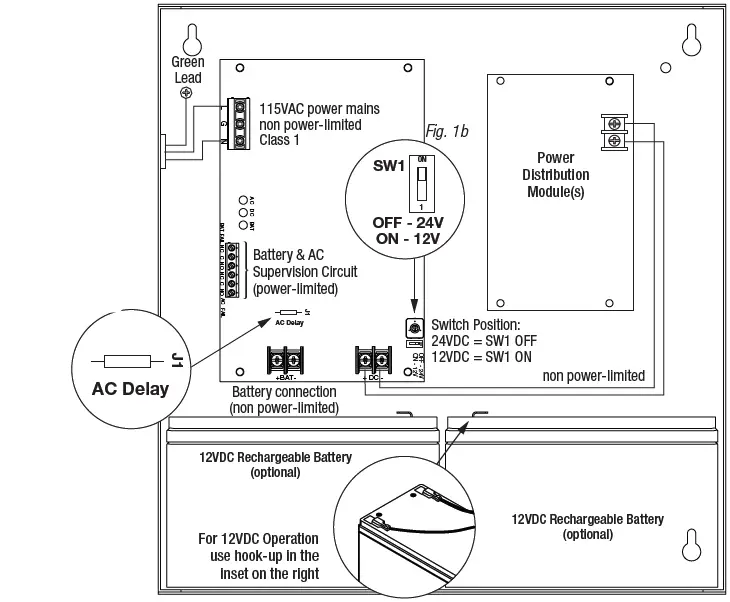
Do not touch exposed metal parts. Shut branch circuit power before installing or servicing equipment. There are no user serviceable parts inside installation and servicing to qualified service personnel. For Fire Alarm applications the outputs. For other devices contact Underwriters Laboratories to ensure compatibility. Set the unit to the desired DC output voltage by setting SW1 to the appropriate position
Power Supply Voltage Output
Measure output voltage before connecting any devices to ensure proper operation. Improper or high voltage will damage these devices. When servicing the unit, AC mains should be removed.
Connect devices to be powered
- For AL600ULX(R) Power Supply: connect devices to the terminals marked + DC –
- For other Power Distribution Models connect devices to be powered to the terminal pairs 1 to 4 marked 1P & 1N through 4P & 4N or 1 to 8 marked 1P & 1N through 8P & 8N carefully observing correct polarity.
- For Access Control applications batteries are optional.
- When batteries are not used, a loss of AC will result in the loss of output voltage. When the use of stand-by batteries is desired, they must be lead acid or gel type.
- Connect appropriate signaling notification devices to the terminals marked AC FAIL & BAT FAIL supervisory relay outputs.
Note
When used in fire alarm or access control applications, AC Fail relay should be utilized to visually indicate that AC power is on. To delay report for 6 hours cut AC Delay jumper. Please ensure that the cover is secured with the provided Key Lock.
Wiring
Use 14 AWG or larger for all power connections.
Note
Take care to keep power-limited circuits separate from non power-limited wiring 115VAC, Battery.
Maintenance:
Unit should be tested at least once a year for the proper operation as follows:
Output Voltage Test: Under normal load conditions the DC output voltage should be checked for the proper
voltage level (Power Supply Voltage Output Specifications Chart, pg. 3).
Battery Test: Under normal load conditions check that the battery is fully charged, check specified voltage both at the battery terminal and at the board terminals marked [+ BAT –] to ensure that there is no break in the battery connection wires.
Note
Maximum charging current under discharges is 0.7A. Expected battery life is 5 years; however, it is recommended changing batteries in 4 years or less if needed.
LED Diagnostics
Power Supply Board
| Red DC | Green AC | Power Supply Status |
| ON | ON | Normal operating condition. |
| ON | OFF | Loss of AC. Stand-by battery supplying power. |
| OFF | ON | No DC output. |
| OFF | OFF | Loss of AC. Discharged or no stand-by battery. No DC output. |
| Red Bat | Battery Status |
| ON | Normal operating condition. |
| OFF | Battery fail/low battery. |
Power Distribution Module
| Green | Power Distribution Module Status |
| ON | Normal operating condition. |
| OFF | No Power Output. |
Terminal Identification
Power Supply Board
| Terminal Legend | Function/Description |
| L, G, N | Connect 115VAC 60 Hz. to these terminals: L to hot, N to Neutral. Do not use the G terminal. |
| + DC – | 12VDC or 24VDC 6A continuous non power-limited output. |
| AC Fail NC, C, NO | Indicates loss of AC power, e.g. connect to audible device or alarm panel. Relay normally energized when AC power is present. Contact rating 1A 28VDC. AC or brownout fail is reported within 1 minute of the event. To delay reporting for up to 6 hrs. cut “AC delay jumper and reset power to unit. |
| Bat Fail NC, C, NO | Indicates low battery condition, e.g. connect to alarm panel. Relay normally energized when DC power is present. Contact rating 1A 28VDC. |
| + BAT – | Stand-by battery connections. Maximum charge current 0.7A. |
Power Distribution Module
| Terminal Legend PD4UL/PD4ULCB | Terminal Legend PD8UL/PD8ULCB | Function/Description |
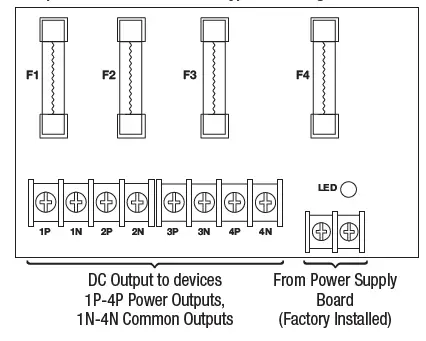
| 1P to 4P | 1P to 8P | Positive DC power outputs. |
| 1N to 4N | 1N to 8N | Negative DC power outputs. |
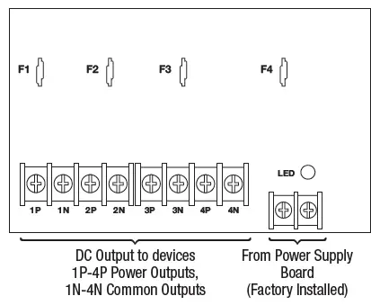
Power Distribution Modules PD4UL Power Distribution Board
Non Power Limited Outputs
Replace fuses with the same type and rating 3.5A/250V
PD4ULCB Power Distribution Board
Class 2 Power Limited Outputs
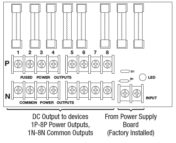
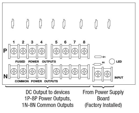
 PD8UL Power Distribution Board
 PD8UL Power Distribution Board
Non Power-Limited Outputs
Replace fuses with the same type and rating 3.5A/250V
Class 2 Power Limited Outputs
Appendix A – UL Listed Compatible Devices
Four (4) Wire Smoke Detectors
Table below lists four (4) wire smoke detectors compatible with AL600ULX output.
| System Sensor Smoke Detector/Base | Detector Type | Max Stand-by Current mA | Alarm Current mA |
| B112LP | Base | 0.12 | 36 |
| B114LP | Base | ||
| B404B | Base | ||
| DH100ACDC | Photoelectric | 0.15 | 0.70 |
| DH100ACDCLP | Photoelectric | 0.15 | 0.70 |
| DH100ACDCLPW | Photoelectric | 0.15 | 0.70 |
| DH400ACDCI | Ionization Duct | 25 | 95 |
| DH400ACDCP | Photoelectric Duct | 25 | 95 |
| 1112/24/D | Ionization | 0.05 | 50 |
| 1424 | Ionization | 0.10 | 41 |
| 1451 (w/B402B Base) | Ionization | 0.10 | 39 |
| 2112/24ATR | Photoelectric | 0.50 | 60/70 |
| 2112/24AITR | Photoelectric | 0.50 | 60/70 |
| 2112/24/D | Photoelectric | 0.05 | 50 |
| 2112/24T/D | Photoelectric w/135o Thermal | 0.05 | 50 |
| 2112/24TSRB | Photoelectric w/135o Thermal Supervisory Relay | 15 | 45 |
| 2312/24TB | Photoelectric | 0.12 | 50 |
| 2412 (12 volt) | Photoelectric | 0.12 | 77 |
| 2424 | Photoelectric | 0.10 | 41 |
| 2451 | Photoelectric | 0.10 | 39 |
| 2451TH (with/B402B Base) | Photoelectric | 0.10 | 39 |
| 2W-MOD | Loop Test/Maintenance Mod. | 30 | 50 |
| 4W-B (12/24 volt) | Photoelectric I3 | 0.05 | 23 |
| 4WT-B (12/24 volt) | Photoelectric I3 w/Therm | 0.05 | 23 |
| 4WTA-B (12/24 volt) | I3 Photo w/Therm/Sounder | 0.05 | 35 |
| 4WTR-B (12/24 volt) | I3 Photo w/Therm/Relay | 0.05 | 35 |
| 4WITAR-B (12/24 volt) | I3 Photo w/Isolated Therm/Sounder/Relay | 0.05 | 50 |
| 2W-MOD2 | I3 Loop Test/Maintenance Mod. | 0.05 | |
| RRS-MOD | I3 Reversing Relay/Sync Module | 0.05 | |
| 6424 | Projected Beam | 10 | 28.4 |
| Beam 1224(S) | Projected Beam | 17 | 38.5 |
Contact manufacturer for current draws.
A.2 Relays
Table below lists relays compatible with AL600ULX output.
| Manufacturer | Model | Current (mA) |
| PR-1 | 15 | |
| PR-2 | 30 | |
| System Sensor | PR-3 EOLR-1 | 30 30 |
| R-10T | 23 | |
| R-14T | 23 |
| Manufacturer | Model | Current mA |
| R-20T | 40 | |
| R-24T | 40 | |
| System Sensor | R-10E R-14E | 23 23 |
| R-20E | 40 | |
| R-24E | 40 |
Enclosure Dimensions BC300
AL600ULX, AL600ULXR, AL600ULPD4, AL600ULPD4CB, AL600ULPD8, AL600ULPD8CB 13.5 x 13 x 3.25 342.9mm x 330.2mm x 82.6mm
Enclosure Dimensions (BC400)
AL600ULXX, AL600ULXXR, AL600ULXPD4, AL600ULXPD4CB, AL600ULXPD8, AL600ULXPD8CB, AL600ULXPD16, AL600ULXPD16CB 15.5 x 12x 4.5 (393.7mm x 304.8mm x 114.3mm
 Altronix is not responsible for any typographical errors 140 58th Street, Brooklyn, New York 1220 USA phone: 718-567-8181 fax: 718-567-9056 website: www.altronix.com e-mail: [email protected] Lifetime Warranty.


