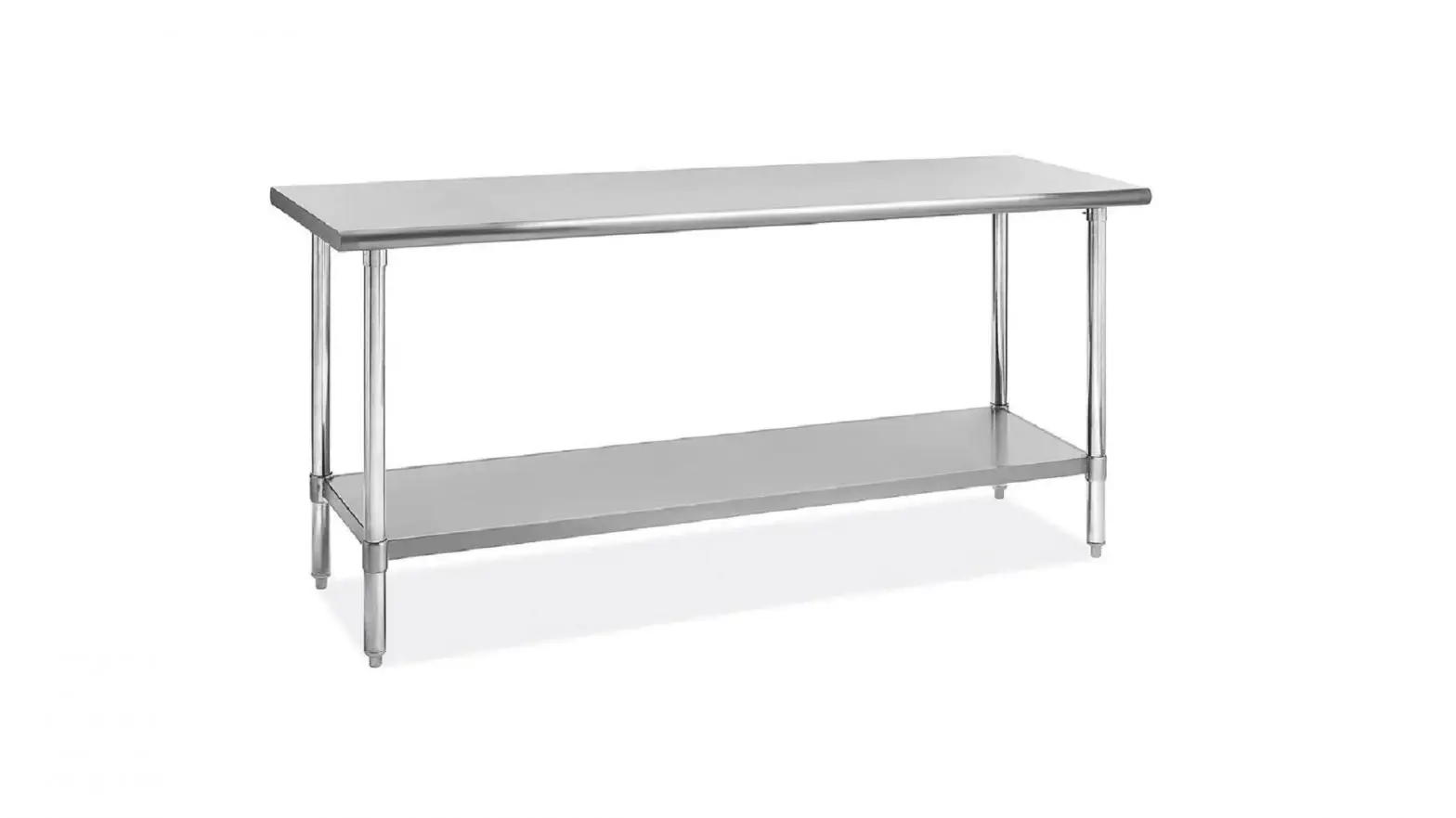
ULINE Stainless Steel Worktable Installation Guide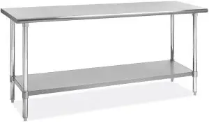

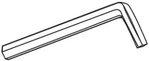
TOOL NEEDED
- 5/32” Allen Wrench (included)

PARTS
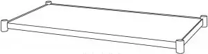
- Tabletop x 1 (H-6259, H-6260, H-6261 include back splash)

- Under shelf x 1

- Legs with Adjustable Feet x 4 (x 6 for H-5345 and H-5691)

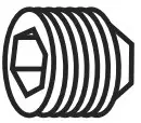
- Set Screw x 8 (x 12 for H-5345 and H-5691)

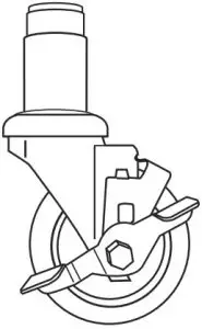
- Caster x 4 (Optional ) (x 6 for H-5345 and H-5691)

ASSEMBLY
![]() NOTE: If purchased with optional casters, adjustable feet will be replaced after complete table assembly
NOTE: If purchased with optional casters, adjustable feet will be replaced after complete table assembly
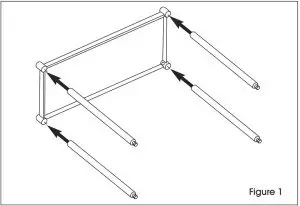
- With the undershelf on its side, push the legs through the collars to the desired To ensure exact height, mark desired height on each leg with magic marker or grease pencil. (See Figure 1)

 NOTE: Each leg must be at the same height or shelf collars could fail. Recommended height from the floor to the top of the undershelf is 10″ and must be 6″ or higher to meet NSF standards NOTE: Optional casters add 3¾” to height.
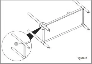
 - Secure legs to undershelf with set screws using 5/32” Allen wrench. (See Figure 2)
 NOTE: Undershelf must be level. Use care not to overtighten screws or failure will occur.
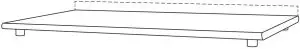
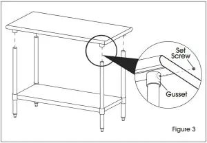
 - Stand table upright and place tabletop onto legs, inserting legs into tabletop gussets. With a 5/32” Allen wrench, tighten set screw on each gusset. (See Figure 3)

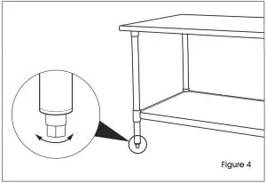
- Level table with the adjustable Adjustable feet allow approximately 1” of adjustment. (See Figure 4)
OPTIONAL CASTERS
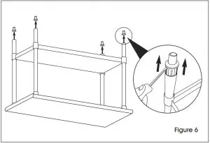
- Flip the table back over onto a smooth, non-marring surface. Remove adjustable feet from tube legs using a flat head screwdriver. (See Figure 6)
 NOTE: You may need to use a rubber mallet or hammer to assist.
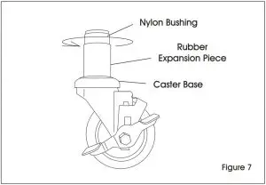
 - Hold caster base and rotate nylon bushing clockwise. This will cause the rubber piece to expand. (See Figure 7)
- Expand the rubber enough so that it will fit snugly into the tube
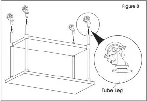
- With caster fully inserted into the leg, turn clockwise until caster is secured to tube leg. (See Figure 8) NOTE: If too loose, pull out caster and tighten further. Repeat step 2.
Contact Us
Phone: 1-800-295-5510
Web: uline.com


