
TORO 08132 Beacon Kit Instruction Manual
Loose Parts
Installation
Use the chart below to verify that all parts have been shipped.
| Procedure | Description | Qty. | Use |
| 1 | No parts required | — | Prepare the machine. |
| 2 | No parts required | — | Remove the canopy. |
| 3 | No parts required | — | Remove the console (if you previously installed the overhead console kit only)and route the wire harness. |
| 4 | Beacon switch | 1 | Install the beacon switch. |
| 5 | Beacon mountBoltNuts | 122 | Install the beacon mount. |
| 6 | BeaconBeacon socket assembly | 11 | Install the beacon. |
| 7 | No parts required | — | Install the canopy. |
Important: You must install the Overhead Console Kit (Model 08130) before you install this kit.
Preparing the Machine
No Parts Required
Procedure
- Park the machine on a level surface.
- Shift the transmission lever to the P (Park) position.
- Shut off the engine and remove the key.
- Disconnect the negative (-) battery cable from the battery post.
Removing the Canopy
No Parts Required
Procedure
Remove the bolts, washers, and spacers securing the canopy (Figure 1) and remove the canopy.
Retain the canopy, bolts, washers, and spacers.
g363987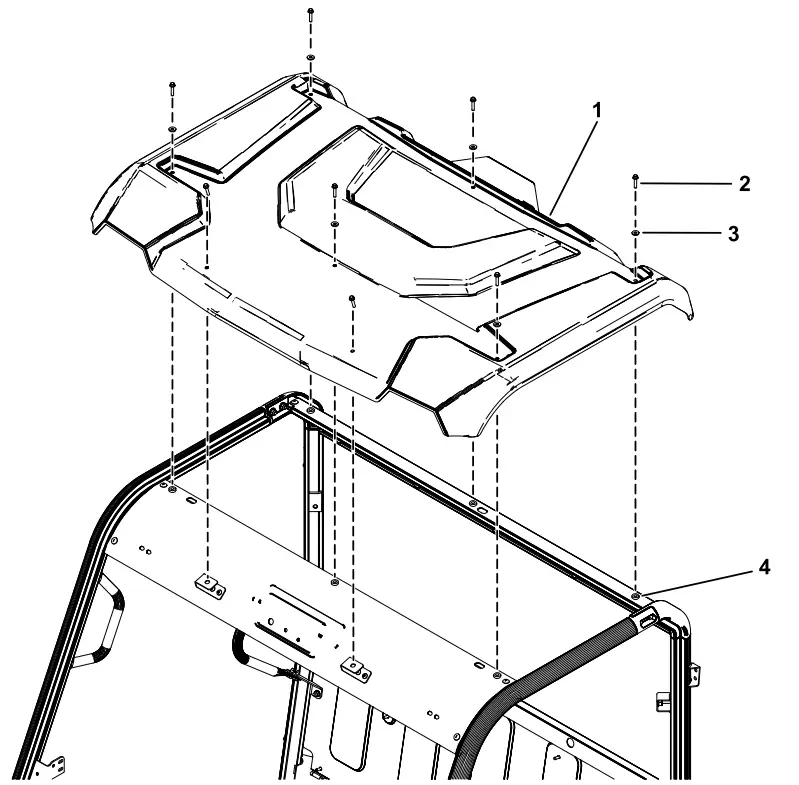
Figure 1
2-person canopy shown
- Canopy
- Hex-head bolt (1/4 x 1-1/4 inches)
- Sealing washer
- Spacer
Removing the Console and Routing the Wire Harness
If You Previously Installed the Overhead Console Kit Only
No Parts Required
Procedure
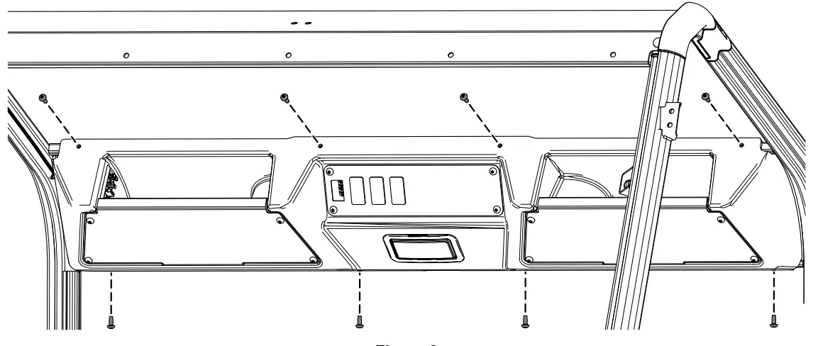
- Remove the 8 screws securing the overhead console and remove the overhead console (Figure 2).
Retain the 8 screws and overhead console for later installation
g363607
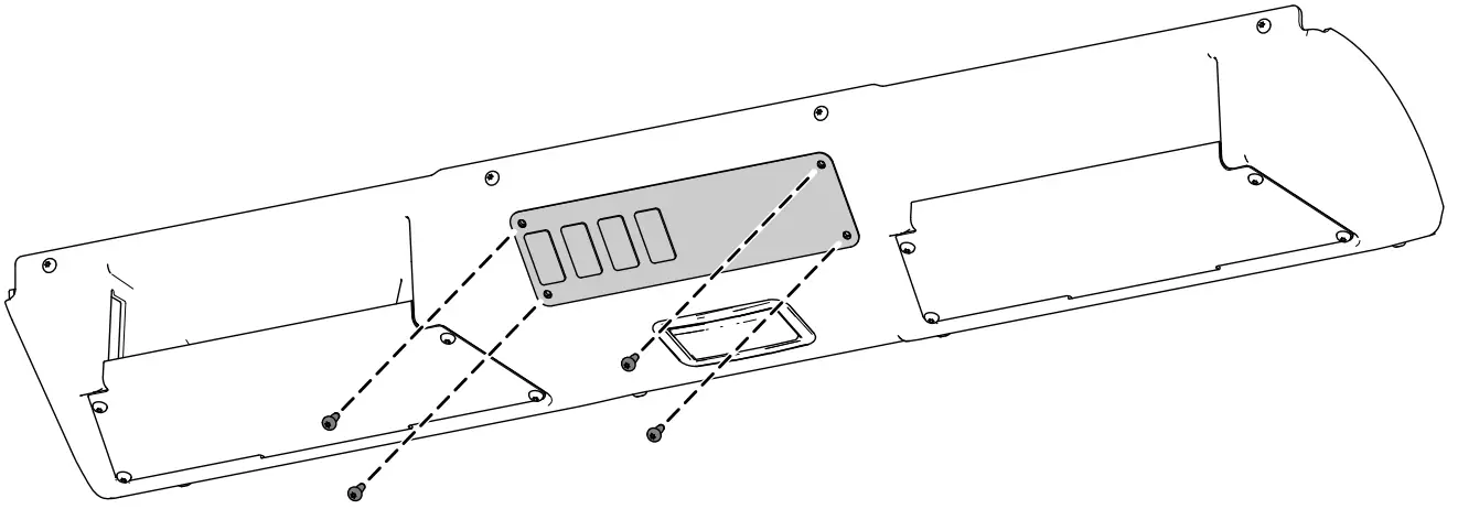
Figure 2 - Remove the console-switch bracket from the overhead console (Figure 3).
Retain the bracket and 4 screws for later installation.
g364119
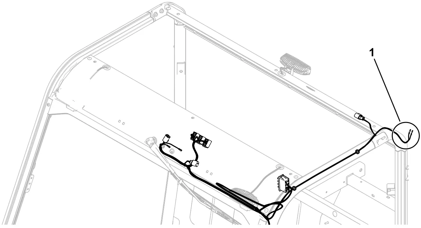
Figure 3 - Route the wire-harness leg with the 2 spade terminals toward the left, rear area of the roll-bar posts (Figure4).
g364200
Figure 4- Spade terminals
- Install the previously removed console using the 8 screws (Figure 2).
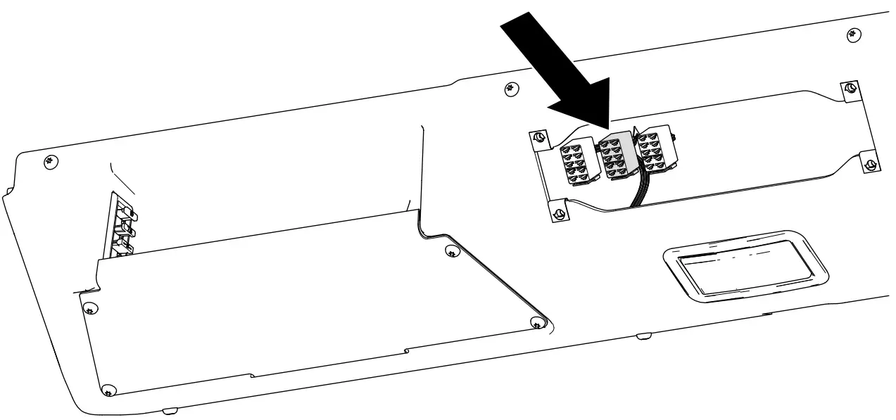
Torque the 8 screws to 339 N∙cm (30 in-lb). - Route the female 8-socket connector labeled BEACON SWITCH through the opening where you removed the console switch bracket (Figure5).
g364198
Figure 5
Installing the Beacon Switch
Parts needed for this procedure:
- Beacon switch
Procedure
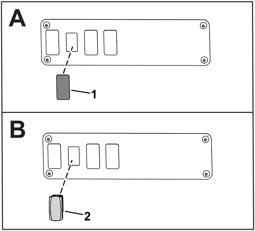
- 1. From the under side of the cab controls panel, press the plug out of the hole shown in Figure 6.
g364024
Figure 6 - Install the switch into the console-switch bracket (Figure 6).
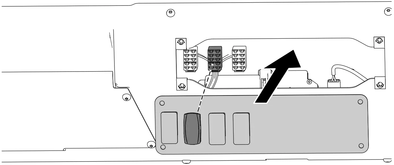
- Align the console-switch bracket into the opening and connect the rocker switch to the female 8-socket connector (Figure 7).
g364199
Figure 7 - Secure the previously removed console-switch bracket to the overhead console (Figure 3). Torque the 4 screws to 11.3 N∙m (100 in-lb).
- Connect the beacon switch to the wire-harness connector labeled BEACON SWITCH into the hole in the control panel (Figure 6).
Installing the Beacon Mount
Parts needed for this procedure:
- 1 Beacon mount
- 2 Bolt
- 2 Nuts
Procedure
Use 2 bolts and 2 nuts to secure the bracket to the left-side rear lifting point of the roll bar as shown in Figure 8.
g363962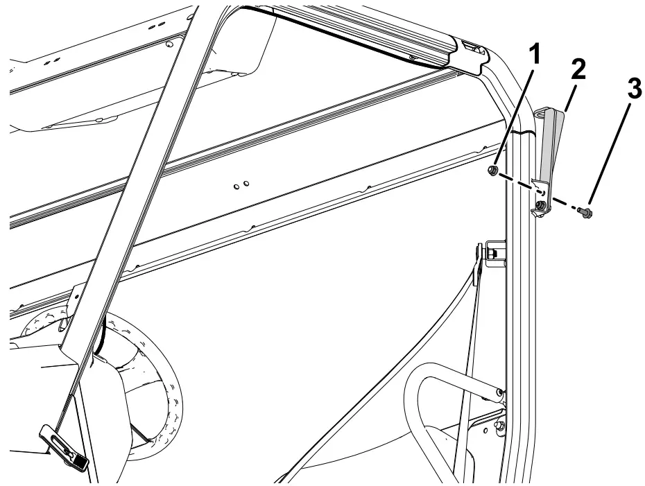
Figure 8
- Nut
- Beacon mount
- Bolt
Installing the Beacon
Parts needed for this procedure:
- 1 Beacon
- 1 Beacon socket assembly
Procedure
- Remove the beacon connector from the beacon socket (Figure 9).
- Route the wire harness up through the jam nut, washer, beacon mount, beacon socket, and connect it to the beacon connector (Figure 9).
- Install the beacon connector into the beacon socket by rotating the beacon socket (Figure 9).
Note: This will prevent twisting of the wire harness. - Mount the beacon socket to the beacon mount with the jam nut included (Figure 9).
- Plug the beacon onto the socket and tighten the wing nut.
g364022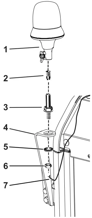
Figure 9
- Beacon
- Beacon connector
- Beacon socket
- Beacon mount
- Washer
- Jam nut
- Wire harness
Installing the Canopy
No Parts Required
Procedure
Secure the previously removed canopy using the bolts, washers, and spacers (Figure 1).
Connecting the Battery
No Parts Required
Procedure
Connect the negative battery cable to the battery post.
Operation
Operating the Beacon Switch
Press the beacon switch to activate and deactivate the beacon.
© 2021—The Toro® Company
8111 Lyndale Avenue South
Bloomington, MN 55420
Register at www.Toro.com
Original Instructions (EN) Printed in the USA All Rights Reserved