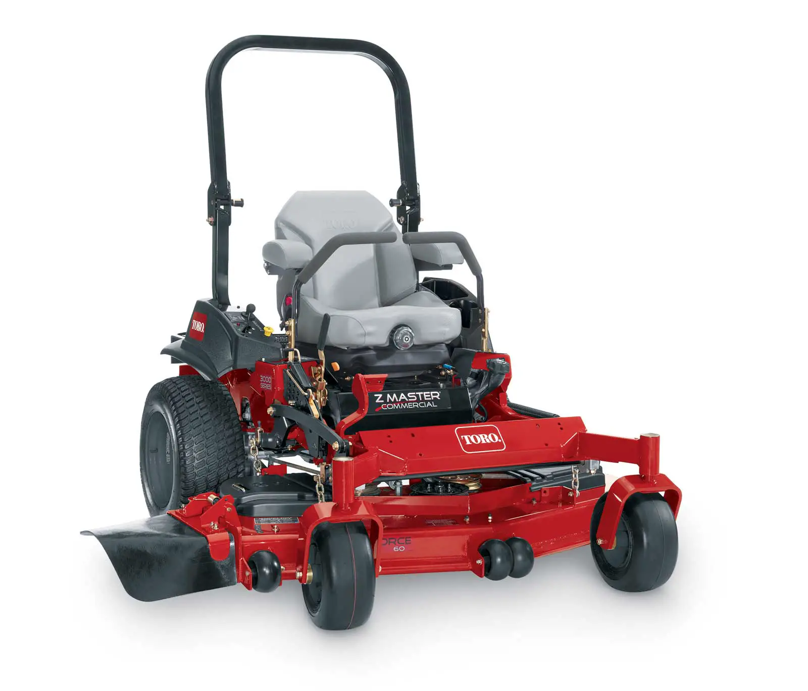
TORO 3000 Z Master Riding Mower
Setup
Loose Parts
Use the chart below to verify that all parts have been shipped.
| Procedure | Description | Qty. | Use |
| 1 | Rear wheels (wooden crate only) | 2 | Remove the machine from a crate. |
| 2 | No parts required | – | Add fuel to the machine. |
| 3 | No parts required | – | Check the engine-oil level. |
| 4 | No parts required | – | Check the tire pressure. |
| 5 | No parts required | – | Check the wheel lug nut torque. |
| 6 | No parts required | – | Check the grass deflector. |
| 7 | J-bolt | 2 | |
| Wing nut | 2 | Install a battery (diesel machines only). | |
| Hold-down clamp | 1 | ||
| 8 | Clamp Wing nut (1/4 inch) Battery hold-down | 1 2 2 | Install a battery (gasoline machines only). |
| 9 | No parts required | – | Charge the battery. |
| Seat | 1 | ||
| Seat plate (fixed seats only) | 1 | ||
| 10 | Flange nuts (3/8 inch)—fixed seats only Spacers (3/8 inch)—fixed seats only Flange nuts (3/8 inch)—tilting seats only | 8 4 4 | Install the seat (international machines using gasoline only). |
| Long spacers (tilting, deluxe seats only) | 2 | ||
| Short spacers (tilting, deluxe seats only) | 4 | ||
| 11 | No parts required | – | Check the seat belt (international machines using gasoline only). |
| 12 | Right control lever | 1 | Install the motion-control levers (international machines using gasoline only). |
| Left control lever | 1 | ||
| Bolt (3/8 x 1 inch)—2 are assembled | 4 | ||
| Nut (3/8 inch)—2 are assembled | 4 | ||
| 13 | Carriage bolt (3/8 x 1-1/2 inches) | 1 | Install the lift-assist pedal (international |
| Flange locknut (3/8 inch) | 1 | machines using gasoline only). |
Original Instructions (EN) Printed in the USA. All Rights Reserved
| Procedure | Description | Qty. | Use |
| 14 | Air-cleaner cap Hose clamp | 1 1 | Install the air-cleaner cap (international machines using gasoline only). |
| 15 | Rollover Protection System (ROPS) Kit | 1 | Install the ROPS (international machines using gasoline only). |
| Roll bar, right section | 1 | ||
| Roll bar, left section | 1 | ||
| Roll bar, center section | 1 | ||
| 16 | Bolt (3/8 x 1 inch) Curved washer | 8 8 | Install the ROPS (diesel machines only). |
| Flange nut (3/8 inch) | 8 | ||
| Bolt (1/2 x 3-1/4 inches) | 2 | ||
| Flange nut (1/2 inch) | 2 | ||
| 17 | No. 2 lithium or molybdenum grease. (Purchase separately.) | 1 tube | Check the machine for grease. |
| 18 | No parts required | – | Remove the shipping straps (for machines with My Ride™ suspension system only). |
| 19 | No parts required | – | Check the machine before delivery to the customer (all machines). |
| Operator’s Manual | 1 | ||
| 20 | Engine Owner’s Manual Registration card Operator training material | 1 1 1 | Deliver the machine to the customer (all machines). |
| Key | 2 |
Removing the Machine from a Crate
Parts needed for this procedure:
- Rear wheels (wooden crate only)
Removing a Machine from a Metal Crate
If you are removing the machine from a metal crate, refer to the Dealer/Distributor Portal for further information.
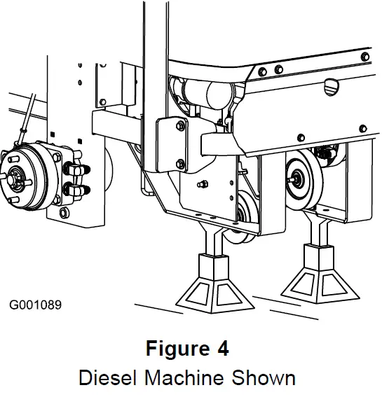
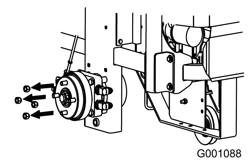
Removing the Machine from a Wooden Crate
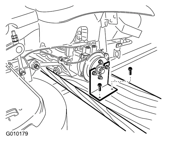
- Remove the screws holding the right angle retaining plate to the crate.
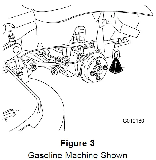
- Raise the rear of the machine and support it with jack stands.


- Remove the wheel nuts from both sides of the machine and remove the right angle retaining plate. Discard the screws and retaining plate.

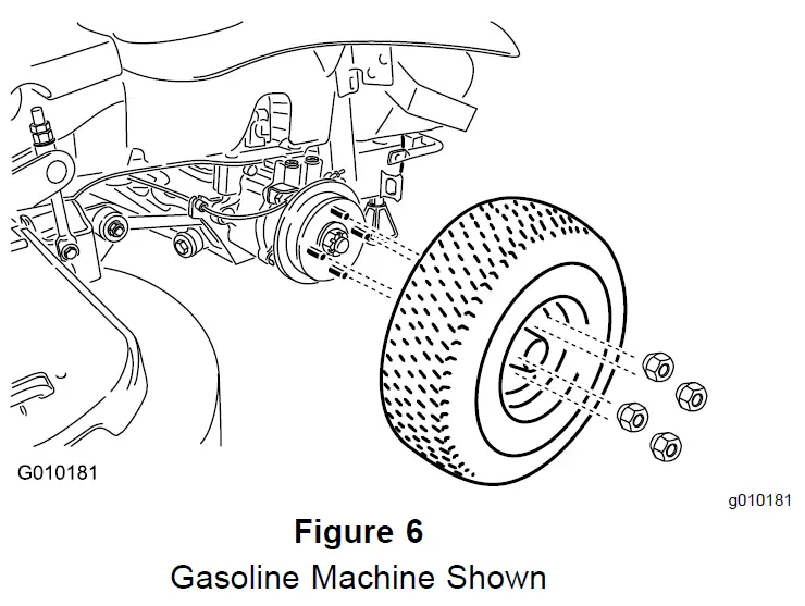
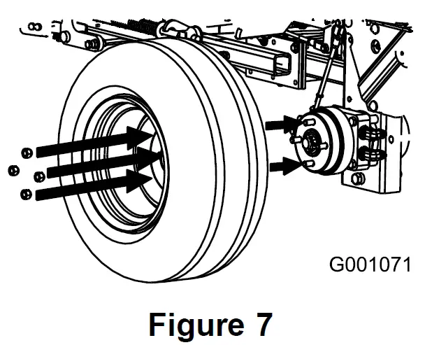
- Mount the wheels with the valve stem to the outside and secure them with the wheel nuts previously removed.
- Torque the wheel nuts to 128 NM (95 ft-lb).
- Remove the jack stands.


Adding Fuel to the Machine
No Parts Required
Procedure
Add fuel to the machine before starting it. Refer to your Operator’s Manual for the correct fuel and procedure.
Checking the Engine-Oil Level
No Parts Required
Procedure
Before you start the engine and use the machine, check the oil level in the engine crankcase; refer to the Operator’s Manual.
Checking the Tire Pressure
No Parts Required
Procedure
Air pressure specification: 90 kPa (13 psi)
Note: Check the tire pressure before starting the machine. Refer to your Operator’s Manual for the correct tire type, correct air pressure needed, and procedure.
Checking the Wheel Lug Nut Torque
No Parts Required
Procedure
Before you start the engine and use the machine, check the wheel lug nut torque; refer to Checking the Wheel Lug Nuts in the Operator’s Manual
Checking the Grass Deflector
No Parts Required
Procedure
If there are plastic ties holding the grass deflector up, remove them and lower the deflector into place.
WARNING
An uncovered discharge opening could allow the machine to throw objects in the operator’s or bystander’s direction and result in serious injury or death. Also, contact with the blade could occur.
Never operate the lawn mower unless you install a cover plate, a mulch plate, grass deflector or bagger.
- Ensure that 1 end of the spring is installed behind the deck edge before installing the bolt as shown in Figure 8.
- Place the other end of the spring around the grass deflector (Figure 8).
Important: The grass deflector must be free to rotate with downward tension. Lift the deflector up to the fully open position and ensure that it rotates freely, without binding into the fully down position.
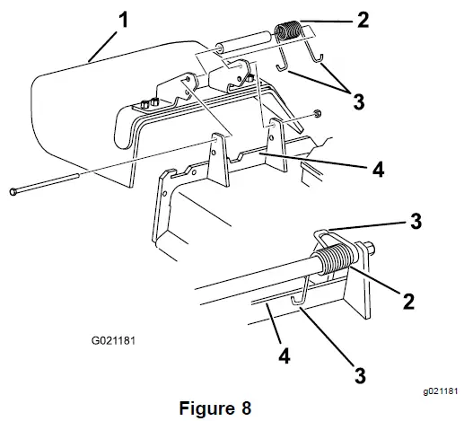
- Grass deflector
- Spring
- End of the spring
- Deck edge
Installing a Battery Diesel Machines Only
Parts needed for this procedure:
| 2 | J-bolt |
| 2 | Wing nut |
| 1 | Hold-down clamp |
Procedure
Important: This procedure only applies to machines that do not come with a battery installed. Purchase a 12V battery and install it into the machine. The engine requires a minimum of 540 CCA. Use the hardware included to install the new battery. Refer to Installing the Battery in the Operator’s Manual.
Installing a Battery Gasoline Machines Only
Parts needed for this procedure:
| 1 | Clamp |
| 2 | Wing nut (1/4 inch) |
| 2 | Battery hold-down |
Procedure
Important: This procedure applies only to machines that do not come with a battery installed.
- Purchase a 12V battery. Models with a 29 hp engine and below require a battery with a minimum of 260 CCA. Models with a 30 hp engine and higher require a battery with a minimum of 340 CCA.
- Locate the battery-mounting hardware and install it into the machine. Refer to Installing the Battery in the Operator’s Manual.
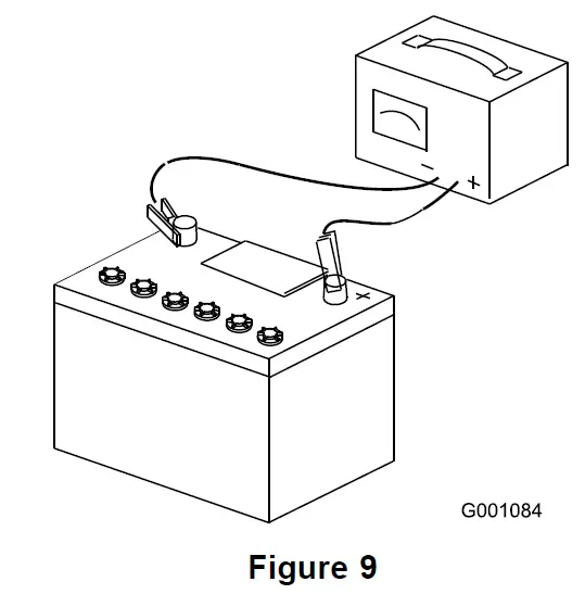
Charging the Battery No Parts Required
Procedure
WARNING
Charging the battery produces gasses that can explode and cause serious injury.
- Keep cigarettes, sparks and flames away from the battery.
- Make sure the ignition switch is off.
- Ventilate when charging or using the battery in an enclosed space.
Important: Do not run the machine with the battery disconnected; electrical damage may occur to the engine.
Charge the battery; refer to the Operator’s Manual for instructions.
Installing the Seat International Machines Using Gasoline Only
Parts needed for this procedure:
| 1 | Seat |
| 1 | Seat plate (fixed seats only) |
| 8 | Flange nuts (3/8 inch)—fixed seats only |
| 4 | Spacers (3/8 inch)—fixed seats only |
| 4 | Flange nuts (3/8 inch)—tilting seats only |
| 2 | Long spacers (tilting, deluxe seats only) |
| 4 | Short spacers (tilting, deluxe seats only) |
Installing the Seat on Models with a Fixed Seat
- Remove the hydraulic-unit shroud from the machine.

- Remove the 4 nuts holding the seat plate to the machine. Discard these nuts, they are used for shipping only.

- Secure the seat plate to the seat with 4 spacers and 4 flange nuts (3/8 inch).

- Plug the harness connector into the seat switch located under the seat towards the front.
- Install the seat to the machine frame with 4 flange nuts (3/8 inch).
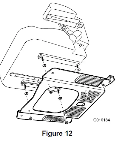
- Harness connector
- Flange nuts
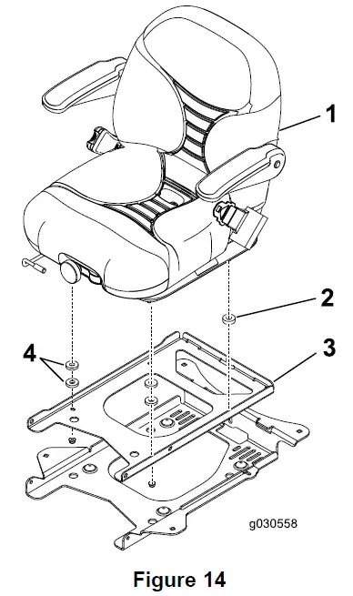
Installing the Seat on Models with a Tilting Seat
- Tilt the seat frame up.
- For deluxe seats only, install the spacers as shown in Figure 14.

- Deluxe seat
- Long spacer
- Seat frame
- Short spacers
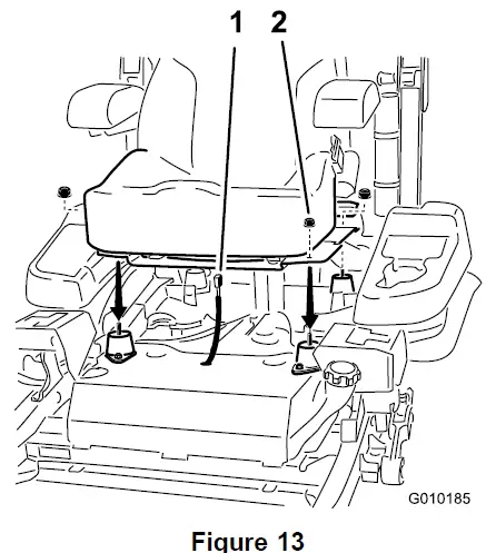
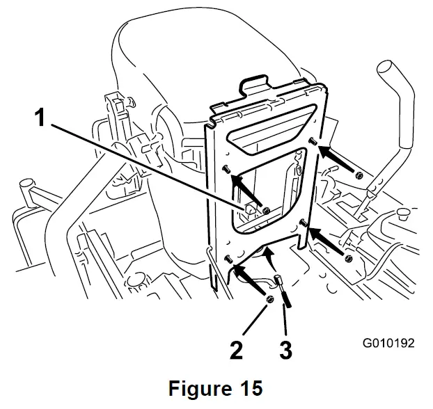
- Install the seat to the seat frame with 4 flange nuts (3/8 inch) as shown in Figure 15.
- Plug the harness connector into the seat switch located under the seat toward the front.

- Seat switch
- Flange nuts
- Harness connector
Checking the Seat Belt International Machines Using Gasoline Only
No Parts Required
Procedure
Important: Ensure the bolt torque is set between 67 to 83 N∙m (49 to 61 ft-lb).
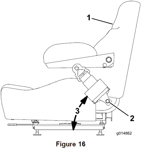
Check the seat belt angle and the seat belt bolt torque before operating.
- Check the angle of the seat belt compared to the bottom of the seat. The angle needs to be 47 degrees (Figure 16).
- If needed, set the seat belt to the correct angle.
- Check and set the bolt torque between 67 to 83 N∙m (49 to 61 ft-lb).

- Side of seat
- Seat belt bolt, set torque between 67 to 83 N∙m (49 to 61 ft-lb).
- 47 degrees
Installing the Motion-Control Levers
International Machines Using Gasoline Only
Parts needed for this procedure:
| 1 | Right control lever |
| 1 | Left control lever |
| 4 | Bolt (3/8 x 1 inch)—2 are assembled |
| 4 | Nut (3/8 inch)—2 are assembled |
Procedure
- Rotate the motion-control levers to the upright position.
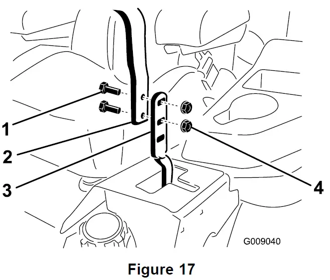
- Loosely install the control levers on the inside of the posts using the 4 bolts and 4 nuts.
Note: Install the control levers in the top and middle holes for the high position or the middle and bottom holes for the low position.
- Bolt (3/8 x 1 inch)
- Handle
- Control lever
- Nut (3/8 inch)
- Raise the levers and align them together in the NEUTRAL position and tighten the bolts.

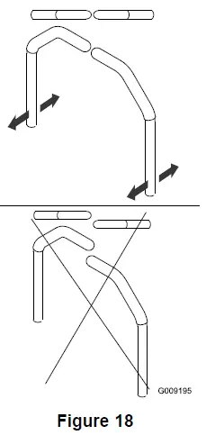
Note: If the machine is not properly tracking, refer to Adjusting the Tracking in your Operator’s Manual.
Installing the Lift-Assist Pedal
International Machines Using Gasoline Only
Parts needed for this procedure:
| 1 | Carriage bolt (3/8 x 1-1/2 inches) |
| 1 | Flange locknut (3/8 inch) |
Procedure
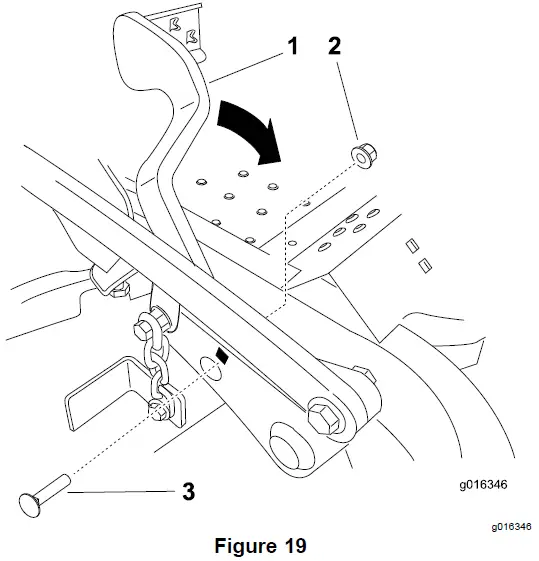
- If needed, loosen the existing bolt and nut for the lift-assist pedal.
- Rotate the lift-assist pedal to the correct position and install the carriage bolt (3/8 x 1-1/2 inches) and locknut (3/8 inch) as shown in Figure 19. Tighten both bolts.

- Lift-assist pedal
- Flange locknut (3/8 inch)
- Carriage bolt (3/8 x 1-1/2 inches)
Installing the Air-Cleaner Cap
International Machines Using Gasoline Only
Parts needed for this procedure:
| 1 | Air-cleaner cap |
| 1 | Hose clamp |
Procedure
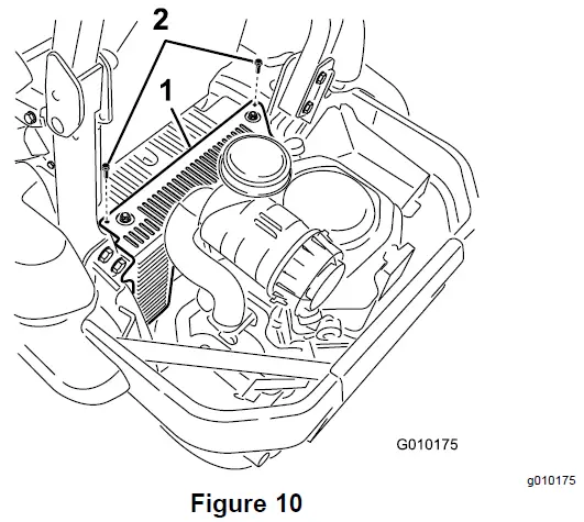
Note: Not all the machines come with a heavy duty air cleaner. This procedure applies only to the models that have a heavy duty air cleaner.
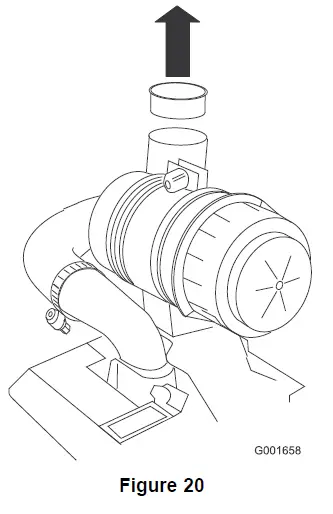
- Remove the plastic plug or tape covering the air cleaner.

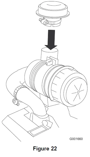
- Install the hose clamp onto the air-cleaner cap.

- Install the air-cleaner cap onto the air cleaner and secure it with the hose clamp.


Installing the ROPS
International Machines Using Gasoline Only
Parts needed for this procedure:
| 1 | Rollover Protection System (ROPS) Kit |
Procedure
Install the Rollover Protection System (ROPS) Kit. Follow the Installation Instructions.
Installing the ROPS
Diesel Machines Only
Parts needed for this procedure:
| 1 | Roll bar, right section |
| 1 | Roll bar, left section |
| 1 | Roll bar, center section |
| 8 | Bolt (3/8 x 1 inch) |
| 8 | Curved washer |
| 8 | Flange nut (3/8 inch) |
| 2 | Bolt (1/2 x 3-1/4 inches) |
| 2 | Flange nut (1/2 inch) |
Procedure
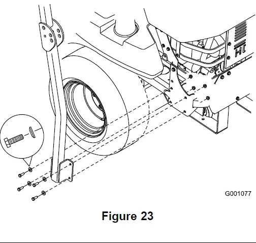
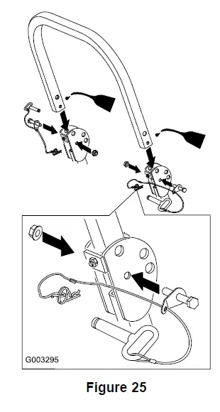
- Loosely install the right and left roll bar section to the frame using the 8 bolts (3/8 x 1 inch), 8 curved washers, and 8 flange nuts (3/8 inch).
Note: Install the curved washer cone toward the bolt head.
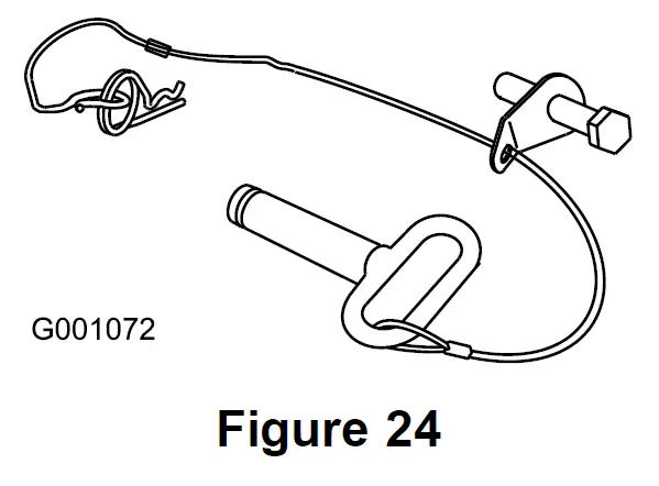
- Install the lanyard clips onto the long bolts (1/2 x 3- 1/4 inches).
Note: Ensure that the bent tab points toward the head of the bolt.
- Lightly oil the ends of the center roll bar section.
- Loosely install the center roll bar section using 2 bolts (1/2 x 3-1/4 inches) and 2 flange nuts (1/2 inch).
Note: Install the bolts from the outside of the roll bar.
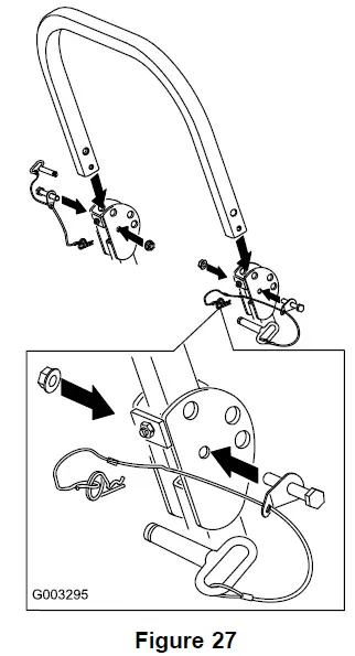
Note: Install the lanyard tab oriented as shown in Figure 25 and pointing forward.
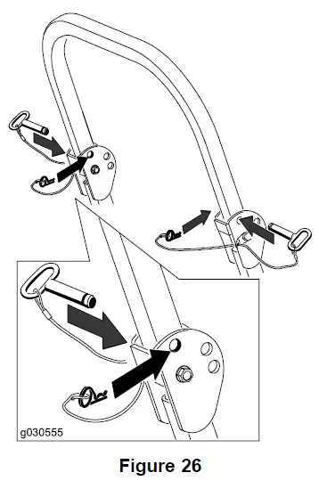
- Raise the roll bar into the upright position and secure it with the pins and hairpin cotters fastened to the lanyards.

- Torque all of the lower fasteners attached to the machine frame to 40.7 N∙m (30 ft-lb).
- Tighten the center roll bar bolts (1/2 x 3-1/4 inches) so that it rotates freely with some resistance.
Note: No more than 1 thread should be exposed outside the nut.
Checking the Machine for Grease
Parts needed for this procedure:
| 1 tube | No. 2 lithium or molybdenum grease. (Purchase separately.) |
Procedure
Before you use the machine, check the machine for grease; refer to Lubrication in the Operator’s Manual.
Removing the Shipping Straps
For Machines with My Ride™ Suspension System Only No Parts Required
Procedure
WARNING
The springs are compressed by the shipping straps. When the straps are cut, the seat will raise up quickly by approximately 8.9 cm (3-1/2 inches).
Note: Ensure that the straps are removed before operating the machine.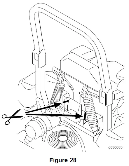
Checking the Machine Before Delivery to the Customer For All Machines
No Parts Required
Procedure
Before delivering the machine to the customer, ensure that you perform or have performed the procedures listed in the following table and initial each when finished. Refer to the Operator’s Manual for instructions on performing these procedures.
| Initial | Check Procedure |
| Check the tire pressure. | |
| Check the level of the machine. | |
| Check that all spindles are greased. | |
| Check the engine-oil level. | |
| Check the hydraulic-fluid level. | |
| Check that the ROPS is secure. | |
| On liquid-cooled machines, check the level of the coolant in the radiator and overflow bottle. | |
| Check the adjustment of the parking brake. | |
| Ensure that the machine tracks correctly; refer to the Operator’s Manual for the adjustment procedure. | |
| Check the safety-interlock system; refer to the Operator’s Manual. | |
| Ensure that the PTO works properly. | |
| Check all the fasteners that you installed and ensure that they are tight. |
When you finish setting up the machine, sign and date in the space provided below:
Delivering the Machine to the Customer
For All Machines
Parts needed for this procedure:
| 1 | Operator’s Manual |
| 1 | Engine Owner’s Manual |
| 1 | Registration card |
| 1 | Operator training material |
| 2 | Key |
Procedure
At delivery, fill in the model and serial number, complete the items listed in the following table, and initial each when finished.
- Model No.
- Serial No.
| Dealer Initial | Customer Initial | Check Procedure |
Show the customer where the following features are located and how they function:
| ||
| Dealer Initial | Customer Initial | Check Procedure |
| ||
| Refer to the Operator’s Manual to point out safety procedures, operation, and maintenance procedures. | ||
| Review the warranty statement as shown in the Operator’s Manual. | ||
| Describe the post sale service procedures for your store. | ||
| Assist the customer in filling out and mailing the registration card or register online at www.Toro.com | ||
| Make sure that the customer receives the Operator’s Manual, Engine Owner’s Manual, Set Up Instructions, and operator training material. | ||
| Make sure the customer knows the Parts Catalog is available at www.Toro.com. | ||
| Assist the customer in loading the machine. |
Note: When you, the dealer representative, have finished delivering the machine to the customer, sign and date in the space provide below and keep a copy of this page for dealer records. Also, the dealer must remind the customer to use a full-width trailer ramp to load the machine.
- Signature:
- Date:
- Signature:
- Date:


