
![]() 145-8399 Groundsmaster®5900 or 5910 Rotary Mower
145-8399 Groundsmaster®5900 or 5910 Rotary Mower
Instruction Manual
Note: Determine the left and right sides of the machine from the normal operating position.
Installation
Loose Parts
Use the chart below to verify that all parts have been shipped.
| Procedure | Description | Qty. | Use |
| 1 | No parts required | – | Prepare the machine. |
| 2 | Template | Drill holes for the idler assembly. | |
| 3 | Idler pulley Idler arm Idler support Spring Flange locknut (3/8 inch) Bolt (1/2 x 1-3/4 inches) Locknut (1/2 inch) Spacer Grease fitting Bushing Hex flange bolt (3/8 x 1-1/4 inches) | 1 1 1 1 1 1 1 1 1 2 2 | Install the idler pulley. |
Preparing the Machine
No Parts Required
Procedure
- Park the machine on a level surface.
- Engage the parking brake.
- Lower the cutting unit.
- Shut off the engine and remove the key.
Drilling Holes for the Idler Assembly
Parts needed for this procedure:
Template
Procedure
- Open the hood.
- Remove the tension on the belt and move the belt away from the installation area.
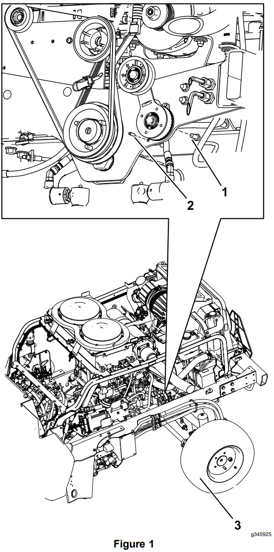
- Remove the roll pin, bolt, and the existing idler pulley shown in Figure 1.
 1. Bolt
2. Roll pin
3. Left rear tire - Align the template to the frame using the holes labeled 1 in Figure Figure 2.
- Punch the location of the holes labeled 3 in Figure 2.
 1. Align holes to frame
2. Template
3. Punch the holes here. - Remove the template.
- Drill 2 holes (13/32 inch) at the punched locations (Figure 3).
 WARNING
Using a drill without proper eye protection may allow debris to enter the eye, causing injury.
When drilling, always wear eye protection. 1. Drill holes (13/32 inch)
 1. Bolt
 1. Align holes to frame
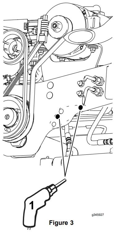 1. Drill holes (13/32 inch)
Installing the Idler Pulley
Parts needed for this procedure:
| 1 | Idler pulley |
| 1 | Idler arm |
| 1 | Idler support |
| 1 | Spring |
| 1 | Flange lockout (3/8 inch) |
| 1 | Bolt (1/2 x 1-3/4 inches) |
| 1 | Locknut (1/2 inch) |
| 1 | Spacer |
| 1 | Grease fitting |
| 2 | Bushing |
| 2 | Hex flange bolt (3/8 x 1-1/4 inches) |
Procedure
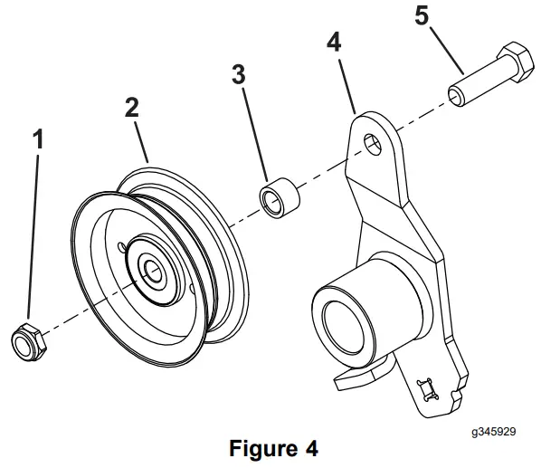
- Install the idler pulley to the idler arm with a bolt (1/2 x 1-3/4 inches), spacer, and 1 lockout (1/2 inch); refer to Figure 4.
 1. Locknut (1/2 inch)
2. Idler pulley
3. Spacer
4. Idler arm
5. Bolt (1/2 x 1-3/4 inches) - Install the grease fitting into the idler support as shown in Figure 5.

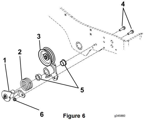
- Install the idler support and idler arm to the frame of the machine with 2 bolts (3/8 x 1-1/4 inches), 2 bushings, a spring, and a nylon lockout (3/8 inch); refer to Figure 6.
- Install the install the spring ends as shown in Figure 7.
 1. Idler support
2. Spring
3. Idler arm
4. Bolt (3/8 x 1-1/4 inches)
5. Bushing
6. Nut (3/8 inch) - Using a ratchet (3/8 inch) in the square in the idler arm, rotate the idler arm and install the belt around the idler pulley (Figure 7).
 1. Spring end
2. Square in idler arm - Close the hood and secure it with the 2 hood latches.
 1. Locknut (1/2 inch)
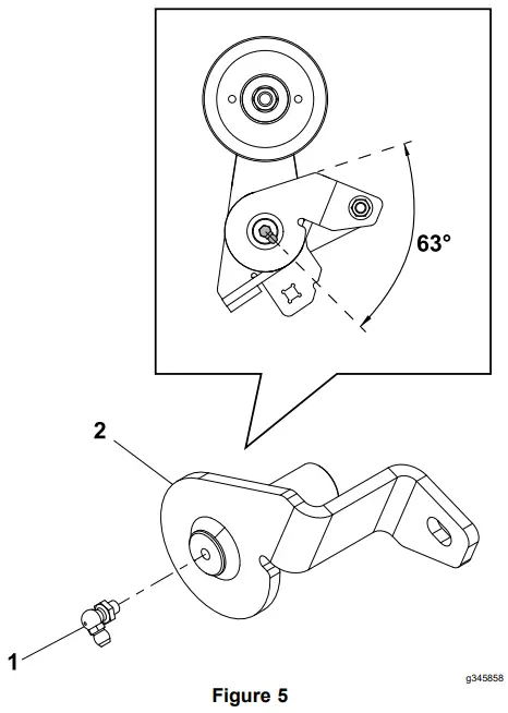
 1. Idler support
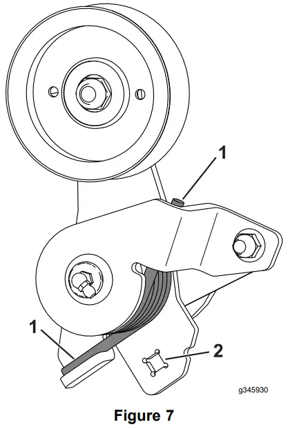 1. Spring end
![]() © 2023—The Toro® Company
© 2023—The Toro® Company
8111 Lyndale Avenue South
Bloomington, MN 55420
Register at www.Toro.com.
Original Instructions (EN)
Printed in the USA
All Rights Reserved Form No. 3462-319 Rev A


