TORO 147-5036 GrandStand Mower with Turbo Force Cutting Unit
Installation
Loose Parts
Use the chart below to verify that all parts have been shipped.
| Procedure | Description | Qty. | Use |
| 1 | No parts required | – | Prepare the machine. |
| 2 | No parts required | – | Remove the deck V-belt. |
| 3 | No parts required | – | Remove the idler arm. |
| 4 | Torsion idler arm | 1 | |
| Bolt (3/8 x 3-1/4 inches) Flange nut (3/8 inch) | 1 1 | Install the torsion idler arm. | |
| Locknut (3/8 inch) | 3 | ||
| 5 | Deck V-belt (122 cm or 48 inches) | 1 | |
| Deck V-belt (132 cm or 52 inches) | 1 | Install the deck V-belt. | |
| Deck V-belt (152 cm or 60 inches) | 1 |
Preparing the Machine
No Parts Required
Procedure
- Park the machine on a level surface.
- Disengage the PTO, engage the parking brake, and move the motion-control levers outward to the NEUTRAL-LOCK position.
- Shut off the engine and remove the key.
- Remove the negative (-) battery cable from the battery.
- Using a floor jack or overhead lifting device, raise the machine until the deck is off the ground.
- Use jack stands or blocks to secure the deck in place.
Removing the Deck V-Belt
- No Parts Required
Procedure
- Remove and discard the deck V-belt; refer to the machine Operator’s Manual.
Removing the Idler Arm
No Parts Required
Procedure
- Remove and discard the bolt (3/8 x 3-1/4 inches) and flange nut (3/8 inch) securing the torsion idler arm to the idler pulley.
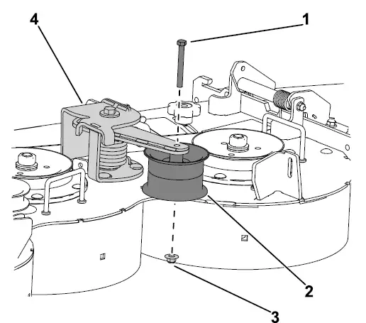
- Bolt (3/8 x 3-1/4 inches)
- Idler pulley
- Flange nut (3/8 inch)
- Torsion idler arm
- From the underside of the deck, install the 3 new locknuts (3/8 inch) that secure the base of the torsion idler arm to the deck. Torque the nuts to 49 to 5 N∙m (36 to 4 ft-lb).
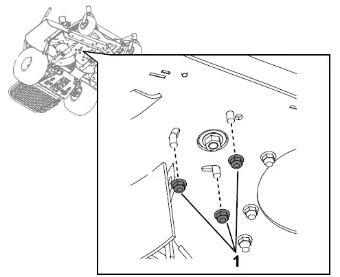
- Flange nuts (3/8 inch)
- Remove and discard the torsion idler arm.
Installing the Torsion Idler Arm
Parts needed for this procedure
| 1 | Torsion idler arm |
| 1 | Bolt (3/8 x 3-1/4 inches) |
| 1 | Flange nut (3/8 inch) |
| 3 | Locknut (3/8 inch) |
Procedure
- Place the new torsion idler arm onto the deck.
- From the underside of the deck, install the 3 new locknuts (3/8 inch) that secure the base of the torsion idler arm to the deck. Torque the nuts to 49 to 5 N∙m (36 to 4 ft-lb).
- Flange nuts (3/8 inch)
- Install the new bolt (3/8 x 3-1/4 inches) and flange nut (3/8 inch) securing the torsion idler arm to the idler pulley. Torque the nut to 49 to 5 N∙m (36 to 4 ft-lb).
- Bolt (3/8 x 3-1/4 inches)
- Idler pulley
- Flange nut (3/8 inch)
- Torsion idler arm
Installing the Deck V-Belt
Parts needed for this procedure
| 1 | Deck V-belt (122 cm or 48 inches) |
| 1 | Deck V-belt (132 cm or 52 inches) |
| 1 | Deck V-belt (152 cm or 60 inches) |
Procedure
- For models with a 122 cm (48 inches) deck, install the new deck V-belt (122 cm or 48 inches); refer to the machine Operator’s Manual.
- For models with a 132 cm (52 inches) deck, install the new deck V-belt (132 cm or 52 inches); refer to the machine Operator’s Manual.
- For models with a 152 cm (60 inches) deck, install the new deck V-belt (152 cm or 60 inches); refer to the machine Operator’s Manual.


