
TORO 31543 4100 Series Rotary Mower

Installation
Note: Install the light adapter kit, Model 30691, on machines that are 2017 and newer. Contact your authorized Toro distributor for the light adapter kit.
Loose Parts
Use the chart below to verify that all parts have been shipped
| Procedure | Description | Qty. | Use |
| 1 | No parts required | – | Disconnect the battery. |
| 2 | Flasher mount | 1 | Install the flasher module. |
| Screw (1/4 x 5/8 inch) | 2 | ||
| Flange nut (1/4 inch) Flasher module Machine screw (#10 x 5/8 inch) | 2 1 1 | ||
| Flat washer (3/16 x 1/2 inch) | 2 | ||
| Locknut (#10) | 1 | ||
| 3 | Switch, turn signal Switch, hazard Wire harness, platform | 1 1 1 | Install the turn signal and hazard switches. |
| 4 | Horn | 1 | Install the horn. |
| 5 | Headlamp bracket—right (for Models | 1 1 2 2 1 1 2 2 1 1 1 2 2 2 | Install the headlights. |
| 30605 and 30609) | |||
| Headlamp bracket—left (for Models | |||
| 30605 and 30609) | |||
| Rubber grommet (for Models 30605 and | |||
| 30609) | |||
| Headlamp bracket (for Models 30643, | |||
| 30635, 30644 and 30636) | |||
| Headlamp bracket—right (for Models | |||
| 30604 and 30608) Headlamp bracket—left (for Models 30604 and 30608) | |||
| Screw (1/2 x 1 inch) | |||
| Locknut (1/2 inch) | |||
| Headlamp—right | |||
| Headlamp—left | |||
| Wire harness, headlight | |||
| Harness clip | |||
| Carriage bolt (1/4 x 5/8 inch) | |||
| Flange nut (1/4 inch) | |||
| 6 | Switch, light | 1 | Install the light switch. |
| 7 | Light mount—left | 1 | Install the rear lamps. |
| Light mount—right Rear lamp assembly | 1 2 | ||
| Harness clip | 2 | ||
| 8 | Fuse (10 A) Fuse (15 A) | 2 1 | Install the fuses. |
| 9 | Screw (#10 x 5/8 inch) | 2 | Install the license mount. |
| Locknut (#10) | 2 | ||
| Plate mount | 1 | ||
| Wire harness Light | 1 1 | ||
| Cable ties | 2 | ||
| Harness clip | 1 | ||
| Jumper wire harness | 2 | ||
| 10 | Decal | 3 | Install the decals. |
Media and Additional Parts
| Description | Qty. | Use |
| Installation instructions | 1 | Read the instructions before installing and operating the kit. |
| Parts catalog | 1 | Use to reference part numbers |
Disconnecting the Battery
Procedure
- Park the machine on a level surface, engage the parking brake, lower the cutting units, shut off the engine, and remove the key.
If you leave the key in the ignition switch, someone could accidently start the engine and seriously injure you or bystanders.
Remove the key from the ignition switch before you do any maintenance. - Disconnect the negative battery cable from the battery post.
Installing the Flasher Module
Parts needed for this procedure:
| 1 | Flasher mount |
| 2 | Screw (1/4 x 5/8 inch) |
| 2 | Flange nut (1/4 inch) |
| 1 | Flasher module |
| 1 | Machine screw (#10 x 5/8 inch) |
| 2 | Flat washer (3/16 x 1/2 inch) |
| 1 | Locknut (#10) |
Procedure
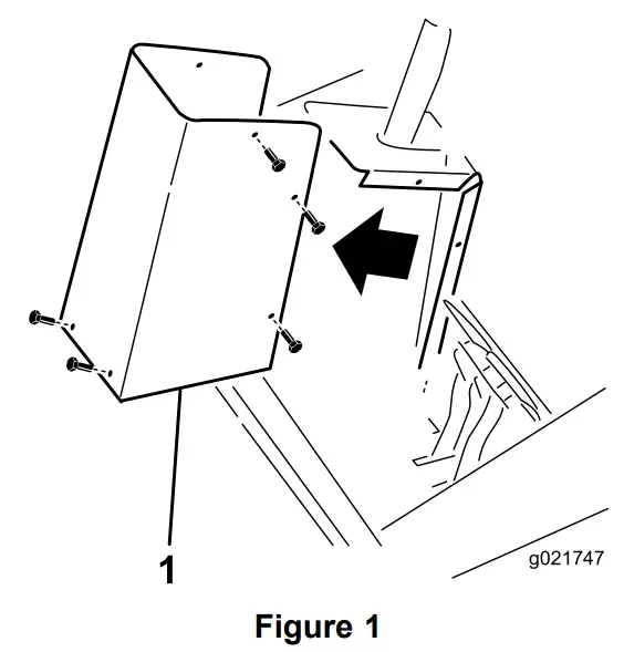
- Remove the steering tower cover from the steering tower (Figure 1).
- Steering tower cover

- Steering tower cover
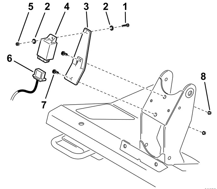
- Secure the flasher mount to the steering tower (Figure 2) with 2 screws (1/4 x 5/8 inch) and flange nuts (1/4 inch).
- Screw (#10 x 5/8 inch)
- Flat washer (3/16 x 1/2 inch)
- Flasher bracket
- Flasher module
- Locknut (#10)
- Wire harness
- Screw (1/4 x 5/8 inch)
- Flange nut (1/4 inch)

- Secure the flasher module to the mount (Figure 2) with a machine screw (#10 x 5/8 inch), 2 flat washers (3/16 x 1/2), and a locknut (#10).
Installing the Turn Signal and Hazard Switches
Parts needed for this procedure:
| 1 | Switch, turn signal |
| 1 | Switch, hazard |
| 1 | Wire harness, platform |
Procedure
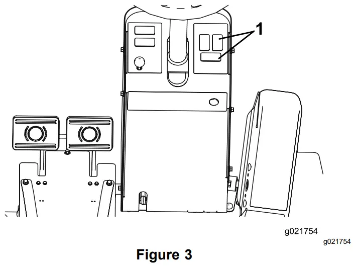
- From the under side of the steering tower dash panel, press the plugs out of the holes shown in Figure 3.
Note: On Models 30643, 30635, 30644, and 30636. the turn signal and hazard switches are already installed on the machine. Skip to Step 4.- Remove these hole plugs

- Remove these hole plugs
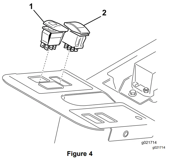
- Install the turn signal switch into the lower hole in of the steering tower dash panel (Figure 4).
The turn signal switch is a On-Off-On switch.- Hazard switch
- Turn signal switch

- Install the hazard switch into the upper right hole in the steering tower dash panel (Figure 4). The hazard switch is a On-None-On switch and has a hazard symbol on it.
- Plug the connector body from the enclosed platform wire harness into the wire harness under the steering cover opening.
Note: On Models 30643, 30635, 30644, and 30636, unplug the existing wire harness connectors from the turn signal and hazard switches. - Plug the connectors from the platform wire harness into the connectors from the flasher module, turn signal and hazard switches (Figure 2).
- Secure the wire harness.
Note: When routing the wires, ensure that the operation of the tilt steering does not damage the harness or pull on the wires.
Installing the Horn
Parts needed for this procedure:
| 1 | Horn |
| 1 | Bolt (5/16 x 3/4 inch) |
| 1 | Flange nut (5/16 inch) |
| 1 | Horn switch |
| 1 | Horn button, rubber |
Procedure
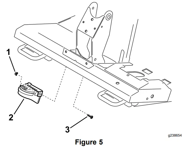
- Install the horn bracket to the tab, under the platform, with a bolt (5/16 x 3/4 inch) and locknut (3/8 inch) (Figure 5). Rotate the horn so it faces toward the back of the machine.
- Flange nut
- Horn (All machines)
- Bolt

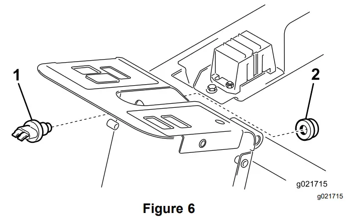
- Insert the horn switch through the hole in the steering column tower (Figure 6).
- Horn switch
- Horn button

- Secure the horn switch to the tower by threading on the rubber horn button (Figure 6).
- Locate the wire harness connectors inside the steering column tower. Plug the wire harness connectors labeled “horn” into the horn and switch.
- Secure the wire harness.
Note: When routing the wires, ensure that the operation of the tilt steering does not damage the harness or pull on the wires.
Installing the Headlights
Parts needed for this procedure:
| 1 | Headlamp bracket—right (for Models 30605 and 30609) |
| 1 | Headlamp bracket—left (for Models 30605 and 30609) |
| 2 | Rubber grommet (for Models 30605 and 30609) |
| 2 | Headlamp bracket (for Models 30643, 30635, 30644 and 30636) |
| 1 | Headlamp bracket—right (for Models 30604 and 30608) |
| 1 | Headlamp bracket—left (for Models 30604 and 30608) |
| 2 | Screw (1/2 x 1 inch) |
| 2 | Locknut (1/2 inch) |
| 1 | Headlamp—right |
| 1 | Headlamp—left |
| 1 | Wire harness, headlight |
| 2 | Harness clip |
| 2 | Carriage bolt (1/4 x 5/8 inch) |
| 2 | Flange nut (1/4 inch) |
For Grounds master 4000, Models 30605 and 30609
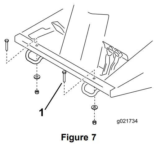
- Remove the 2 bolts, washers and nuts from the front of the operator’s platform (Figure 7).
- Bolt, washer and nut (2)

- Bolt, washer and nut (2)
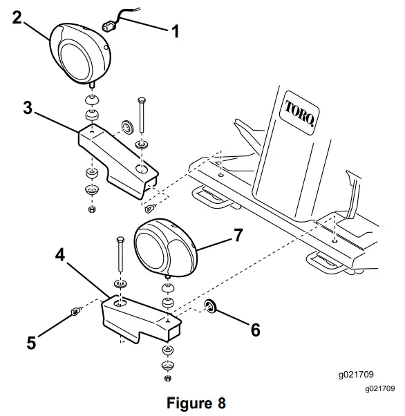
- Install a rubber grommet into the hole in each headlight bracket (Figure 8).
- Fasten the right and left headlight brackets to the front of the operator’s platform with the bolts, washers and nuts previously removed. Position the brackets as shown in Figure 8.
- Wire harness
- Headlight assembly—right
- Headlight bracket—right
- Headlight bracket—left
- Harness clip
- Rubber grommet
- Headlight assembly—left

- Fasten the right and left headlight assemblies to the headlight brackets (Figure 8) with the fasteners supplied with the lights. Make sure that the turn signal lens on the headlight is positioned toward the outside of the machine.
- Plug the connector body from the enclosed headlight wire harness into the harness connector of the steering tower wire harness under the steering cover opening.
- Route the headlight wire harness underneath the front edge of the operator’s platform.
- Insert each harness connector through the end of the appropriate harness bracket, out the hole (grommet) and connect it to the headlight (Figure 8).
- Secure the headlight wire harness to the headlight brackets and operator’s platform with the harness clips and cable ties.
- Install the steering tower cover.
For Grounds master 4010 and 4110, Models 30643, 30635, 30644 and 30636
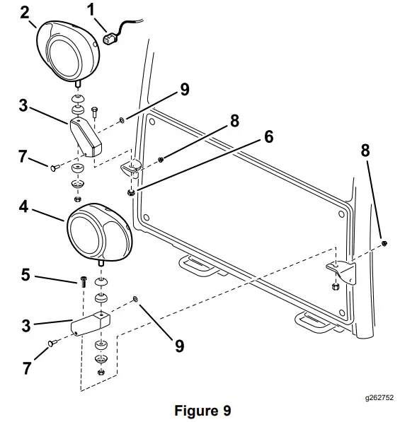
- Fasten the headlight brackets to the existing brackets on the front of the cab with screws (1/2 x 1 inch) and locknuts (1/2 inch). Position the brackets as shown in Figure 9.
- Install a rubber grommet into the hole in each headlight bracket (Figure 9).
- Install the headlight bracket to the cab with 2 carriage bolts (1/4 x 5/8 inch) and 2 flange nuts (1/4 inch).
- Wire harness
- Headlight assembly—right
- Headlight bracket (2)
- Headlight assembly—left
- Screw (1/2 x 1 inch)
- Locknut (1/2 inch)
- Carriage bolt (1/4 x 5/8 inch)
- Flange nut (1/4 inch)
- Grommet

- Fasten the right and left headlight assemblies to the headlight brackets (Figure 9) with the fasteners supplied with the lights. Make sure the turn signal lens on the headlight is positioned toward the outside of the machine.
- Plug the connector bodies from the enclosed headlight wire harness into the harness connectors of the steering tower wire harness.
- Route the headlight wire harness underneath the front edge of the operator’s platform and connect it to the headlights (Figure 9).
- Secure the headlight wire harness to the operator’s platform with the harness clips and cable ties.
- Install the steering tower cover.
- The front and rear cab lights cannot be used for CE applications. Disable the front and rear cab lights as follows:
• Front-Pop the lights out of the cab roof and disconnect the wires from the lights. Reinstall the lights into the cab.
• Rear-Remove the screws securing the lenses to lights. Remove the bulbs from the lights and reinstall the lenses to the lights.
For Groundsmaster 4100, Models 30604 and 30608
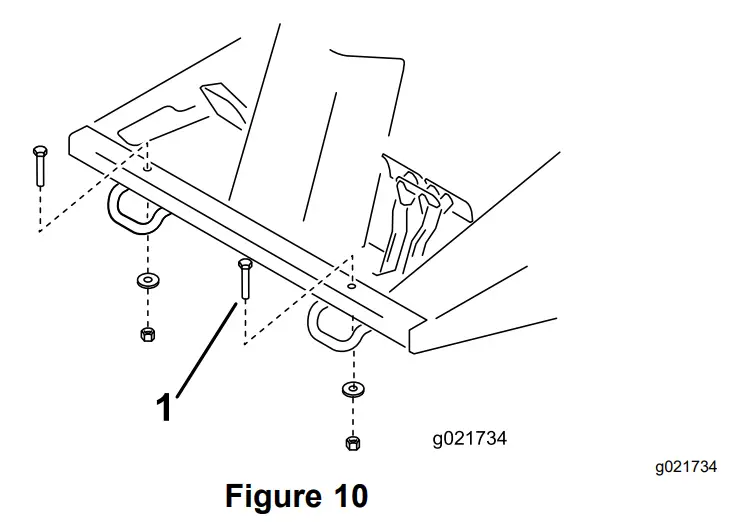
- Remove the 2 bolts, washers and nuts from the front of the operator’s platform (Figure 10).
- Bolt, washer and nut (2)

- Bolt, washer and nut (2)
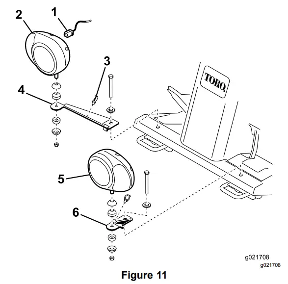
- Fasten the right and left headlight brackets to the front of the operator’s platform with the bolts, washers and nuts previously removed. Position the brackets as shown in Figure 11.
- Fasten the right and right headlight assemblies to the headlight brackets (Figure 11) with the fasteners supplied with the lights. Make sure the turn signal lens on the headlight is positioned toward the outside of the machine.
- Plug the connector body from the enclosed headlight wire harness into the harness connector of the steering tower wire harness under the steering cover opening.
- Route the headlight wire harness underneath the front edge of the operator’s platform and connect it to the headlights (Figure 11).
- Wire harness
- Headlight assembly—right
- Harness clip
- Headlight bracket —right
- Headlight assembly—left
- Headlight bracket—left

- Secure the headlight wire harness to the headlight brackets and operator’s platform with the harness clips and cable ties.
- Install the steering tower cover.
Installing the Light Switch
Parts needed for this procedure:
| 1 | Switch, light |
Procedure
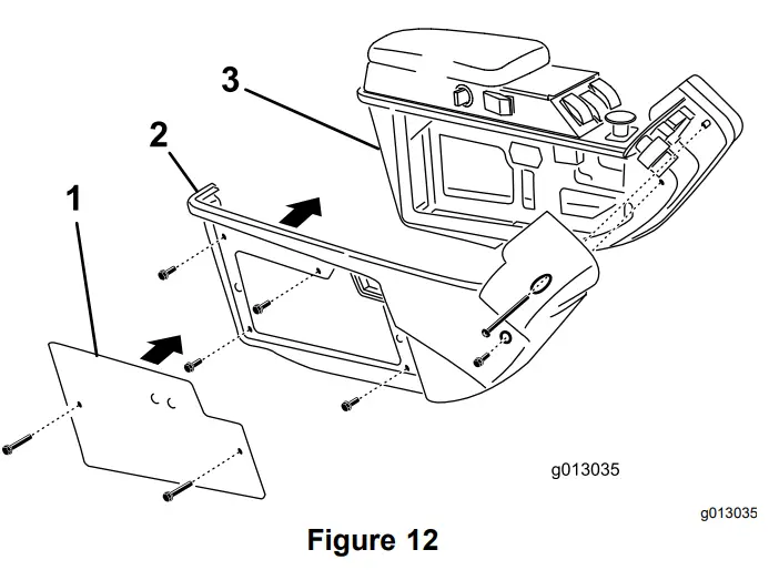
- Remove the 2 screws that secure the plate to the right cover of the control arm (Figure 12).
- Plate
- Right cover
- Control arm

- Remove the 6 screws that secure the right cover to the right side of the control arm (Figure 12).
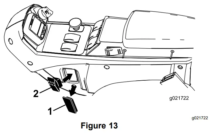
- From inside the control arm switch panel, press the plug out of the hole in the side of the control panel (Figure 13).
- Plug
- Switch

- Press the switch into the control panel mounting hole (Figure 13).
- Locate the wire harness under the control panel. Plug the wire harness connector labeled “lights” into the switch.
- Install the cover and plate to the right side of the control arm.
Installing the Rear Lamps
Parts needed for this procedure:
| 1 | Light mount—left |
| 1 | Light mount—right |
| 2 | Rear lamp assembly |
| 2 | Harness clip |
Procedure
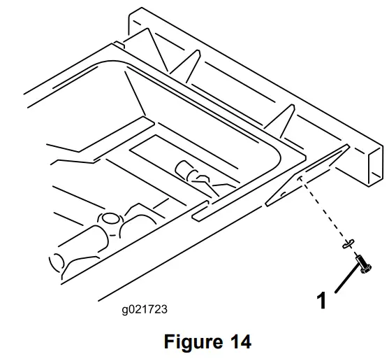
- Remove the top bolt, washer and nut securing the rear bumper bracket to the left frame rail (Figure 14). Retain the bolt, washer and nut.
- Rear bumper bracket bolt, washer and nut

- Rear bumper bracket bolt, washer and nut
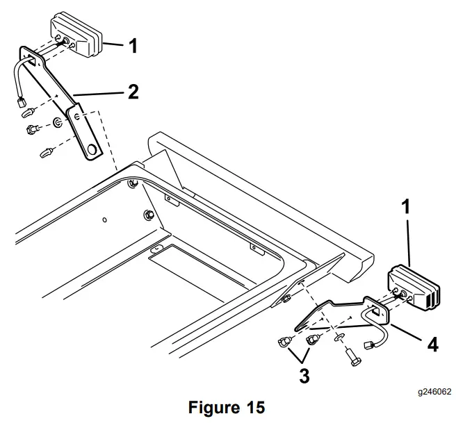
- Using the bolt, washer and nut previously removed, secure the left lamp mount to the bracket and frame (Figure 15). Make sure that the bottom hole in the lamp mount is positioned over the bottom bumper mounting bolt.
Note: The left and right lamp mounts are different. Make sure to use the correct mount.- Rear lamp (2)
- Lamp mount—right
- Harness clip
- Lamp mount—left

- Mount the rear lamp to lamp mount with bolts and nuts included with the lamp (Figure 15).
Note: Make sure that the lamp is positioned so that the plug is through the hole in the lamp mount and the amber end is toward the outside of the machine. - Repeat the procedure on the right side of the machine.
Installing the Fuses
Parts needed for this procedure:
| 2 | Fuse (10 A) |
| 1 | Fuse (15 A) |
Procedure
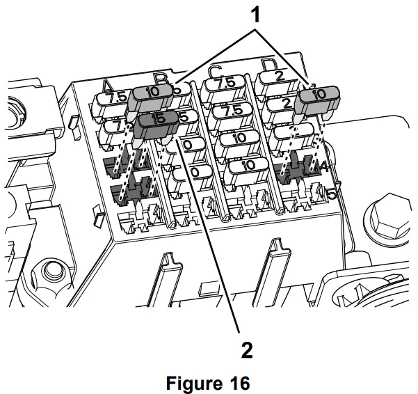
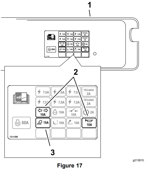
- Insert a fuse (10 A) into fuse-block slot at row 3, column A (Figure 16 and Figure 17).
- Insert a fuse (15 A) into fuse-block slot at row 4, column A (Figure 16 and Figure 17).
- Insert the other fuse (10 A) into fuse-block slot at row 4, column D (Figure 16 and Figure 17).
- Fuses (10 A)
- Fuses (15 A)

- Cover
- Fuse (10 A) locations on decal
- Fuse (15 A) location on decal

Installing the License Plate Mount
Parts needed for this procedure:
| 2 | Screw (#10 x 5/8 inch) |
| 2 | Locknut (#10) |
| 1 | Plate mount |
| 1 | Wire harness |
| 1 | Light |
| 2 | Cable ties |
| 1 | Harness clip |
| 2 | Jumper wire harness |
Procedure
- Open the hood.
- Remove the cotter pins from the catch rods on each side of the hood.
- Remove the 2 cotter pins securing the rear hood to the frame pivots and lift the hood off the machine.
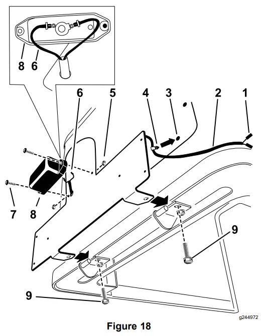
- Remove the rear screws that secure the hood pivot mounts to the hood (Figure 18). Important: Only remove the rear screw from each hood pivot mount.
- Route the wire harness through the plate mount and plug the bullet connectors into the light (Figure 18).
- Remove the existing screen fastener to install the push-in fastener (Figure 18).
- Mount the light to the plate mount with 2 screws (#10 x 5/8 inch) and 2 locknuts (#10).
Note: Ensure that the lens points downward and do not over tighten the fasteners. - Using the 2 screws previously removed, install the plate mount to the hood pivot mounts (Figure 18).
- Install the push-in fastener into the open screen hole (Figure 18).
- Harness connectors
- Wire harness
- Remove the existing screen fastener.
- Push-in fastener
- Locknut (#10)
- Bullet conectors
- Screw (#10 x 5/8 inch)
- Light
- Rear screw

- Install the hood and secure it with the cotter pins.
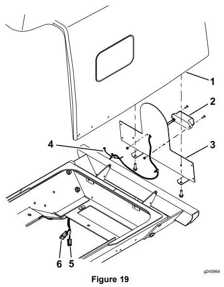
Note: Ensure that the light wires are routed between the hood and the frame. - Connect the license plate light wire harness as follows (Figure 19):
• If machine has a tail light installed, unplug the tail light from the machine wire harness.
• Plug the machine harness connector into license-plate light wire harness.
Note: The machine harness connector is located on the left side of the machine.
• If machine has a tail light installed, plug the left tail light connector into the open connector on the license-plate light wire harness (Figure 19).- Hood
- Light
- Plate mount
- Harness clip
- Tail-light connector
- Connector for machine harness

- Secure the wires to the frame with the harness clip, and the cable tie (Figure 19).
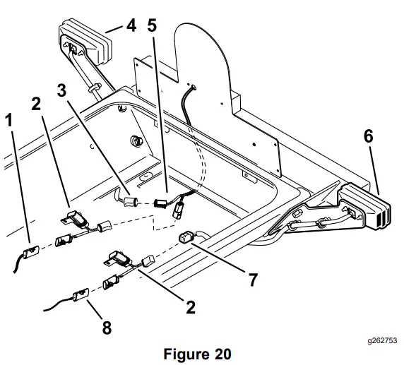
- On each side, plug the enclosed jumper wire harness into the harness connectors of the machines rear wire harness (Figure 20).
- Route the right harness under the right side of the traction unit to the right rear lamp. Plug the tail light connectors into the right-lamp pig tail connector and the jumper wire harness (Figure 20).
- Route the left harness under the left side of the traction unit to the left rear lamp. Plug the jumper wire harness connector into the left-lamp pig tail connector (Figure 20).
- Secure the wire harness and jumper wires the harness clips and cable ties.
- Right side connector
- Jumper wire harness
- Light connector
- Right lamp
- Tail light connectors
- Left lamp
- Light connector
- Left side connector

- Secure the remaining wires with the cable ties.
Important: Ensure that the wires are clear of all hot, sharp or moving components. - Close and secure the hood.
- Check the operation of the license plate light.
Installing the Decals
Parts needed for this procedure:
| 3 | Decal |
Procedure
Note: Only install the decals when they are required for your machine.
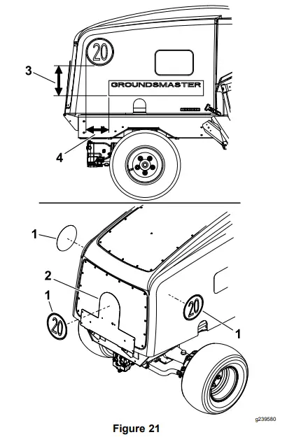
Clean the area on the machine for the decals and install the decals as shown in Figure 21.
- Decal
- Plate mount
- 21.6 cm (8-1/2 inches)
- 16.5 cm (6-1/2 inches)

Connecting the Battery
Procedure
Connect the negative battery cable to the battery post.
Operation Controls
Light Switch
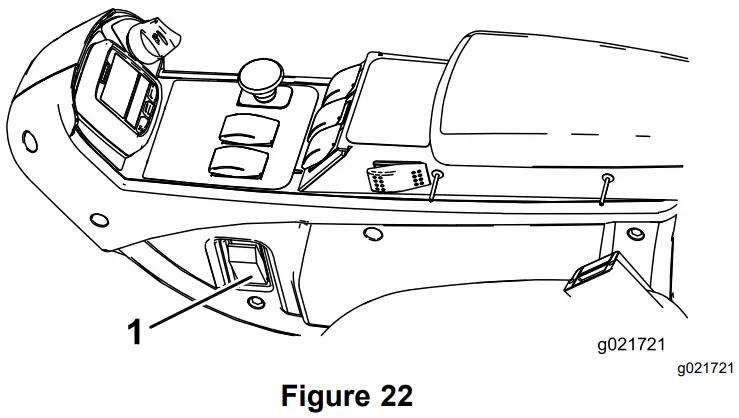
Press the light switch (Figure 22) to the ON position to activate the head lamps.
- Light switch

Hazard Switch
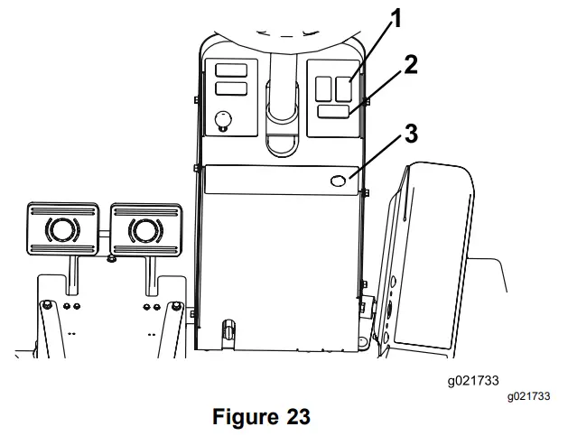
Press the hazard switch (Figure 23) to the On position to activate the front and rear flashing hazard lights.
- Hazard switch
- Turn signal switch
- Horn button

Turn Signal Switch
Press down on the left side of the turn signal switch (Figure 23) to activate the left turn signal. The center position is off.
Press down on the right side of the turn signal switch (Figure 23) to activate the right turn signal. The center position is off.
Horn
Press the horn button to activate the horn (Figure 23).
Aiming the Headlights
- Loosen the mounting nuts and position each headlight so that it points straight ahead.
- Tighten each mounting nut just enough to hold the headlight in position.
- Place a flat piece of sheet metal over the face of the headlight.
- Mount a magnetic protractor onto the plate.
- While holding the assembly in place, carefully tilt the headlight downward 3 degrees, then tighten the nut.
- Repeat the procedure for the other headlight.