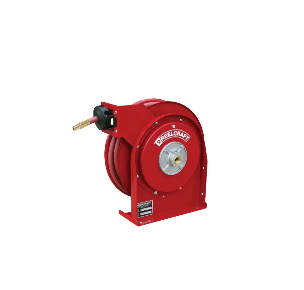
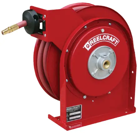
REELCRAFT A5800 OLP Series 5000 Spring Driven Hose Reels
Dimensions
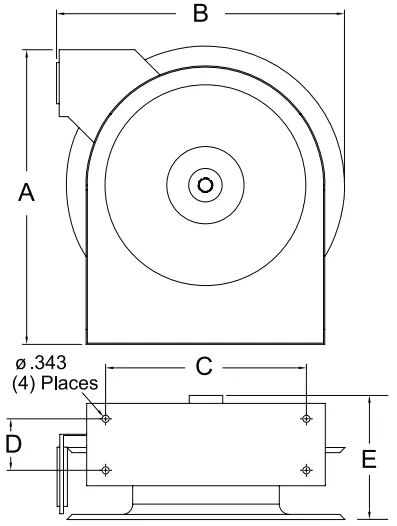 | A | 14 3/8” |
| B | 14” | |
| C | 9 3/4” | |
| D | 2 1/2” | |
| E | 6 1/8” |
SAFETY
INSTALLATION: A flexible hose connection must be used between the hose reel inlet and the source of supply to prevent possible misalignment and binding.
MOUNTING: The hose reel is equipped with a universal mounting bracket so that it can be mounted on the floor, wall or ceiling; whichever place is convenient. The hose guide arm can be moved to the position desired by removing the screws fastening the guide bracket to the reel base. Shift the guide arm bracket so the hose comes off the reel at the desired position and replace the screws. NOTE: For proper installation in wall mount applications, ensure reel is mounted with inlet on the right as you are facing the reel. Failing to do so could cause latching issues.
LUBRICATION: Hose reel spring and bearings are factory lubricated and require no further lubrication.
REPLACING HOSE:
- Wind spool flange clockwise-facing swivel-until spring is tight.
- Back off three turns and latch.
- Insert hose through roller guide.
- Connect hose fitting to swivel joint and secure hose with clamps.
ADJUSTMENTS: To adjust spring tension, add or remove wraps of hose from the spool, one wrap at a time until desired tension is obtained.
REPAIRS: Extensive repairs should be performed only by an authorized serviceman or factory to avoid damage which may void your warranty. Remove all spring tension before beginning disassembly process.
Overview
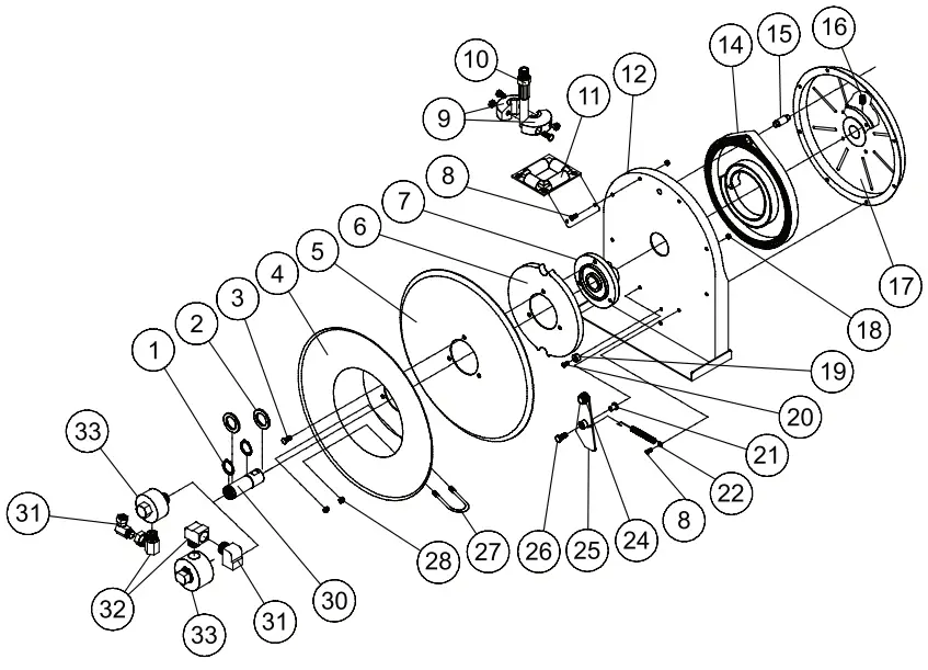
Item # | Part # | # Req. | Description |
| 1 | 300031 | 2 | 1” Snap Ring |
2 | 300034 | 2 | Spacing Washer |
| 3 | S295-102 | 3 | 1/4-10 Hex Head Screw |
4 | 260022 | 1 | Flange Sheave |
| 5 | 500006 | 1 | Sheave Disk |
6 | S500019 | 1 | Latch Cam |
| 7 | S260648 | 1 | Spring Arbor |
8 | 300002 | 7 | 10-32 x 1/2” Mach. Screw |
| 11 | S500107 | 1 | Guide Arm & Roller Assembly |
12 | 500101 | 1 | Base Assembly |
| 14 | S505740 | 1 | Drive Spring Assembly |
15 | S261360 | 1 | Spring Case Stud |
| 16 | 300006 | 1 | 3/8-16 x 1/2” Set Screw |
17 | S500103 | 1 | Spring Case & Hub Assembly |
| 18 | S82-15 | 8 | 10-32 x 3/8” Nyloc Nut |
19 | S400021 | 1 | Latch Bumper |
| 20 | S32-136 | 1 | 10-24 x 3/8” Self Tap Screw |
21 | S400012 | 1 | Latch Bushing |
| 22 | S400018 | 1 | Latch Spring |
24 | 400020 | 1 | O-ring |
| 25 | S400109 | 1 | Latch Plate Assembly |
26 | 300035 | 1 | 10-32 x 1” Mach. Screw |
| 27 | 3-117440 | 1 | U-bolt Hose Clamp |
28 | 261650-1 | 2 | 1/4-20 Zinc Nyloc Nut |
| 30 | 602305 | 1 | Main Shaft & Snap Ring Assembly |
Item # | Description | # Req. | A5800 OLP | A5825 OLP | A5800 OMP | A5825 OMP |
| 9 | Bumper Stop Assembly | 1 | None | 2-HR1004-3 | None | 2-HR1004-3 |
10 | Hose Assembly | 1 | None | 601020-25 | None | 21-260043 |
| 31 | Swivel Union | 1 | S257-26 | S257-26 | 260749 | 260749 |
32 | Swivel Union | 1 | 300010 | 300010 | S257-26 | S257-26 |
| 33 | Swivel Assembly | 1 | S600915-1 | S600915-1 | S600172 | S600172 |
Hose I.D. and Length | None | 1/2” x 20’ | 1/2” x 25’ | 1/2” x 30’ | ||
| Reel Inlet Connection | 3/8” F.P.T. | 3/8” F.P.T. | 3/8” F.P.T. | 3/8” F.P.T. | ||
Max. Operating Pressure | 500 P.S.I. | 300 P.S.I. | 3250 P.S.I. | 3250 P.S.I. | ||
| Max. Operating Temperature | 210 °F | 150 °F | 210 °F | 210 °F | ||
Customer Support
Reelcraft Industries, Inc. • 2842 E Business Hwy 30, Columbia City, IN 46725
Ph: 800-444-3134 / 260-248-8188 • Fax: 800-444-4587 / 260-248-2605
Customer Service: 855-634-9109 • [email protected] • www.reelcraft.com