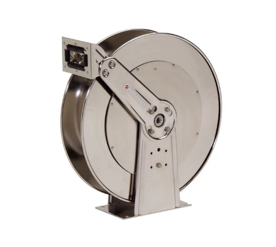
REELCRAFT 81000 OLS 80000 Series Stainless Steel Hose Reels Instruction Manual
Operating Instructions
IMPORTANT
Read this manual carefully before installing, operating or servicing this equipment.
Dimensional Data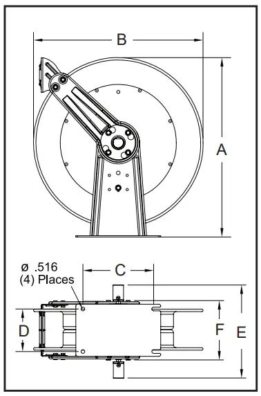
| A | 25 3/8” |
| B | 24” |
| C | 10” |
| D | 6” |
| E | 10 1/2” |
| F | 8 1/8” |
Personal Safety
Personal injury and/or equipment damage may result if proper safety precautions are not observed.
- Ensure that reel is properly installed before connecting input and output hoses.
- Bleed fluid/gas pressure from system before servicing reel.
- Before connecting reel to supply line, ensure that pressure does not exceed maximum working pressure rating of reel.
- Remember, even low pressure is very dangerous and can cause personal injury or death.
- Be aware of machinery and personnel in work area.
- If a leak occurs in the hose or reel, remove system pressure immediately.
- A high tension spring assembly is contained within the reel. Exercise extreme caution.
- Pull hose from reel by grasping the hose itself, not the control valve.
- If reel ceases to unwind or rewind, remove system pressure immediately.
Do not pull or jerk on hose! - Treat and respect the hose reel as any other piece of machinery, observing all common safety practices.
INSTALLATION INSTRUCTIONS
WARNING: Ensure that reel, hose, and equipment are properly grounded. Use an ohmmeter to check ground continuity.
Mounting
CAUTION: Unless reel was specified differently when ordering, maximum installation height is 16 feet.
Do not exceed this distance.
Maximum Operating Temperature:
Low pressure (300 psi) = 150 °F (66 °C)
Medium pressure (2000 psi) = 210 °F (99 °C)
- Unpack and inspect reel for damage.
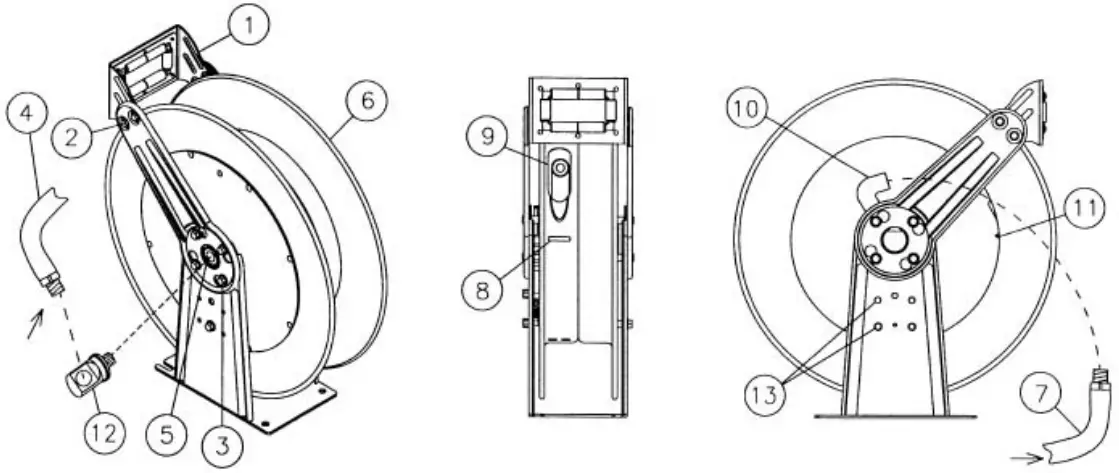
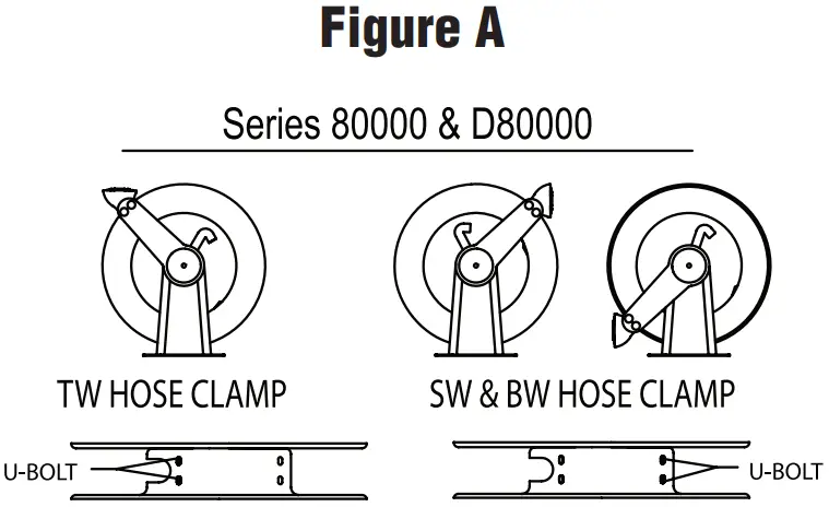
Turn by hand to check for smooth operation. Check for completeness. - Configure reel for top, side or bottom hose dispensing by removing the bolts (2) from one side of the guide roller bracket and loosening the four guide arm bolts (3) on each side of the hose reel.
Rotate and remove each guide arm then reinstall in the desired configuration.
If bottom wind is desired, bolts (13) and bolts (2) must be removed and replaced after the guide arm is in position.
CAUTION: When changing guide arm positions, the U-bolt must be placed in the proper location as instructed in figure A.
The reel can “latch out” during use if this instruction is not adhered to. - Position reel on floor, wall, or ceiling. Secure into place using four (customer supplied) bolts.
Installing the Input Hose
WARNING: Ensure that supply line pressure does not exceed maximum working pressure rating of reel. Apply pipe thread sealant to all threads on standard reels.
Do not overtighten connection. Recommended torque not to exceed 70 ft. lb.
CAUTION: Use flexible hose connection at input. Do not use rigid plumbing.
- Apply thread sealant as directed and connect swivel (12) to main shaft input (5).
- For standard shaft and swivel reels, connect customer supplied inlet hose (4) to swivel input as indicated in illustration.
Installing the Output Hose
WARNING: Use extreme caution; reel under tension. Avoid releasing latch mechanism.
CAUTION: Apply pipe thread sealant to all threads on standard reels.
Do not overtighten connection.
Recommended torque not to exceed 70 ft. lb.
- Manually turn sheave (6) until spring is tight, back off 3 turns, then latch.
- Route output hose (7) through roller bracket (1), U-bolts (8), then through cutout (9) in spool as indicated in illustration.
- Connect output hose (7) to gooseneck (10) as indicated in illustration.
- Verify U-bolt position conforms with guide arm position using label inside spool.
Then tighten nuts (11) on U-bolt (8). - Charge hose. Momentarily open control valve to purge hose of gases.
When fluid appears at control valve, close valve.
With hose fully charged, release latch and wind output hose onto reel. - Install bumper stop assembly
ADJUSTMENTS
WARNING: Use extreme caution; reel under tension. Avoid releasing latch mechanism.
If necessary, adjust spring tension on reel by manually adding or removing wraps of hose from spool, one wrap at a time, until desired tension is obtained.
Manually add wraps to increase tension.
Remove wraps to decrease tension.
CAUTION: When adding wraps of hose, add just enough wraps to achieve the desired tension without exceeding the winding mechanism’s spring capacity.
Properly tensioned reels allow all hose to be freely removed from the spool until the point of U-bolt contact.
Damage to the winding mechanism will result if spring is over-tensioned.
SERVICE INSTRUCTIONS
User servicing of the reel is limited to replacing input/output hoses only.
Refer all other repairs to an authorized service person or directly to Reelcraft.
Failure to do so may result in personal injury and/or equipment damage and may void the warranty.
WARNING: Rewind hose on reel, then bleed pressure from system before performing the following procedures.
CAUTION: Remove all spring tension before disassembling the hose reel.
Do not attempt to open the riveted spring case assembly.
- Replace hoses in accordance with procedures given in “Installation Instructions” section of this manual.
- All mating moving parts have been factory lubricated as required.
Parts List
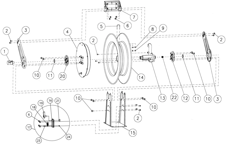
| # | DESCRIPTION | QTY | 81000 OLS | 81000 OLS-S | 82000 OLS | 82000 OLS-S | 83000 OLS | 83000 OLS-S | 81000 OMS | 81000 OMS-S | 82000 OMS | 82000 OMS-S | 83000 OMS | 83000 OMS-S |
| 1 | Swivel assembly** | 1 | S600092-2 | 602654-2 | S600092-2 | 602654-2 | S600091-2 | 602653-2 | S600092-2 | 602654-2 | S600092-2 | 602654-2 | S600091-2 | 602653-2 |
| 1 | Swivel assembly | 1 | S602682-2 | 602654-2 | S602682-2 | 602654-2 | S600091-2 | 602624-2 | S602682-2 | 602654-2 | S602682-2 | 602654-2 | S600091-2 | 602624-2 |
| 2 | 5/16-18 x 1/2” flange screw | 11 | * | * | * | * | * | * | * | * | * | * | * | * |
| 3 | Guide arm | 2 | 261455 | 261455 | 261455 | 261455 | 261455 | 261455 | 261455 | 261455 | 261455 | 261455 | 261455 | 261455 |
| 4 | Spring & case assembly | 1 | S600726-2 | S600726-2 | S600726-2 | S600726-2 | S600726-1 | S600726-1 | S600726-2 | S600726-2 | S600726-5 | S600726-5 | S600726-4 | S600726-4 |
| 5 | U-bolt | 1 | * | * | * | * | * | * | * | * | * | * | * | * |
| 6 | 5/16-18 locknut | 8 | * | * | * | * | * | * | * | * | * | * | * | * |
| 7 | Roller bracket assembly | 1 | S600728 | S600728 | S600728 | S600728 | S600728 | S600728 | S600728 | S600728 | S600728 | S600728 | S600728 | S600728 |
| 8 | .312 ID x .734 OD washer | 2 | * | * | * | * | * | * | * | * | * | * | * | * |
| 9 | 1/4-20 locknut | 2 | * | * | * | * | * | * | * | * | * | * | * | * |
| 10 | 3/8-16 x 5/8” screw | 9 | * | * | * | * | * | * | * | * | * | * | * | * |
| 11 | 1 3/8” snap ring | 2 | * | * | * | * | * | * | * | * | * | * | * | * |
| 12 | Flange w/bearing & nut-sert | 1 | S600724 | S600724 | S600724 | S600724 | S600724 | S600724 | S600724 | S600724 | S600724 | S600724 | S600724 | S600724 |
| 13 | Ratchet, flow casting** | 1 | 261306-2 | 602652-1 | 261306-2 | 602652-1 | 261306-1 | 602652-2 | 261306-2 | 602652-1 | 261306-2 | 602652-1 | 261306-1 | 602652-2 |
| 13 | Ratchet, flow casting | 1 | S261306-6 | 602652-1 | S261306-6 | 602652-1 | 261306-1 | 602652-2 | S261306-6 | 602652-1 | S261306-6 | 602652-1 | 261306-1 | 602652-2 |
| 14 | Sheave assembly | 1 | 600723 | 600723 | 600723 | 600723 | 600723 | 600723 | 600723 | 600723 | 600723 | 600723 | 600723 | 600723 |
| 15 | Base & upright assembly | 1 | 600722 | 600722 | 600722 | 600722 | 600722 | 600722 | 600722 | 600722 | 600722 | 600722 | 600722 | 600722 |
| 16 | Latch mounting bracket | 1 | 261465 | 261465 | 261465 | 261465 | 261465 | 261465 | 261465 | 261465 | 261465 | 261465 | 261465 | 261465 |
| 17 | Latch pawl & mounting bracket | 1 | S600729-1 | S600729 | S600729-1 | 600729 | S600729-1 | 600729 | S600729-1 | 600729 | S600729-1 | 600729 | S600729-1 | 600729 |
| 18 | Latch spring | 1 | S260067 | S260067 | S260067 | S260067 | S260067 | S260067 | S260067 | S260067 | S260067 | S260067 | S260067 | S260067 |
| 19 | Latch pawl assembly | 1 | S600069-1 | S600069 | S600069-1 | S600069 | S600069-1 | S600069 | S600069-1 | S600069 | S600069-1 | S600069 | S600069-1 | S600069 |
| 20 | Bearing & flange assembly | 1 | S600725 | S600725 | S600725 | S600725 | S600725 | S600725 | S600725 | S600725 | S600725 | S600725 | S600725 | S600725 |
| 21 | 1/2-20 hex nut | 1 | * | * | * | * | * | * | * | * | * | * | * | * |
| 22 | Pipe plug | 1 | * | * | * | * | * | * | * | * | * | * | * | * |
| 23 | 10-32 shoulder screw | 1 | S393-2 | S393-2 | S392-2 | S392-2 | S392-2 | S392-2 | S392-2 | S392-2 | S392-2 | S392-2 | S392-2 | S392-2 |
| 24 | 10-32 x 3/8” Nyloc nut | 1 | * | * | * | * | * | * | * | * | * | * | * | * |
Included in hardware kit part number 600737
Prior to August 2016 See online tech bulletin for more information
CUSTOMER SUPPORT
Reelcraft Industries, Inc.
2842 E Business Hwy 30, Columbia City, IN 46725
Ph: 800-444-3134 / 260-248-8188
Fax: 800-444-4587 / 260-248-2605
Customer Service: 855-634-9109
[email protected]
www.reelcraft.com