
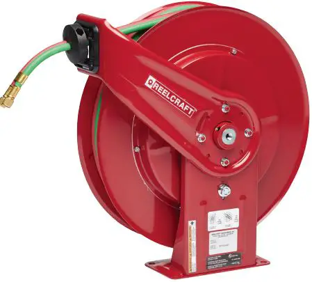
REELCRAFT TW450 OLPT Welding Hose Reels
IMPORTANT
Read this manual carefully before installing, operating or servicing this equipment.
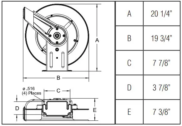
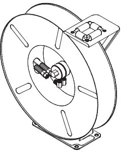
Dimensions
SAFETY
Personal injury and/or equipment damage may result if proper safety precautions are not observed.
- Ensure that reel is properly installed before connecting input and output hoses.
- Bleed fluid/gas pressure from system before servicing reel.
- Before connecting reel to supply line, ensure that pressure does not exceed maximum working pressure rating of reel.
- Remember, even low pressure is very dangerous and can cause personal injury or death.
- Be aware of machinery and personnel in work area.
- If a leak occurs in the hose or reel, remove system pressure immediately.
- A high tension spring assembly is contained within the reel. Exercise extreme caution.
- Pull hose from reel by grasping the hose itself, not the control valve.
- Ensure that reel, hose, and equipment being serviced are properly grounded. Use an ohmmeter to check ground continuity.
- If reel ceases to unwind or rewind, remove system pressure immediately. Do not pull or jerk on hose!
- Treat and respect the hose reel as any other piece of machinery, observing all common safety practices.
IN-SERVICE CAUTION
- The user is cautioned not to shut off the fuel gas at the regulator or supply source first, as a flashback may result, and thereby damage the hose.
- Users are cautioned specifically to shut off the gas at the torch first, and then at the regulator or supply source, to limit permeation of gas through the hose wall. This should be done when the torch will not be used for periods in excess of 30 minutes.
- After the flame has been extinguished and the gas turned off at the supply source, it is recommended that any remaining gas be bled to minimize degradation of the rubber during long shutdowns.
- To prevent an accumulation or concentration of gas that could be explosive or otherwise harmful to personnel, ade-quate ventillation must be provided at all times, particularly in confined areas where fuel gas is being used.
- Additional advice for minimizing the permeation problem has been supplied by an NWSA member who states “The source of gas (fuel gas and oxygen) should be closed before leaving for the day or shift. After the cylinder or manifold valves have been closed, the torch valves (both fuel gas and oxy-gen) should be opened to remove all pressure from hoses.
INSTALLATION INSTRUCTIONS
MOUNTING
Caution: Unless reel was specified differently when ordering, maximum installation height is 16 feet. Do not exceed this dis-tance. Observe all applicable NEC, OSHA & local codes when installing this equipment.
- Unpack and inspect reel for damage. Turn by hand to check for smooth operation. Check for completeness.
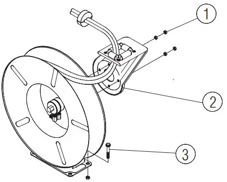
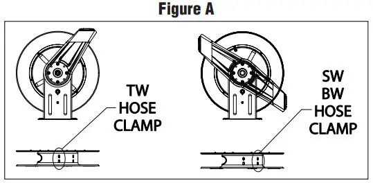
- Configure reel for top, side, or bottom-wind hose dispensing by removing bolts (or nuts) (1) securing guide arm bracket (2). Caution: When changing guide arm positions, the U-bolt must be placed in the proper location as instructed in figure A below. The reel can “latch out” during use if this instruction is not adhered to.
- Determine new guide arm bracket location and remove cor-responding bolts, (or nuts). Position guide arm bracket to reel and replace bolts (or nuts).
- Position reel on floor, wall or ceiling. Secure into place using four (customer supplied) screws or bolts (3).
INSTALLING THE INPUT HOSES
Caution: Apply teflon tape to all input connections to insure a proper seal.
INSTALLING THE OUTPUT HOSES
Caution: Use extreme caution; reel under tension, avoid releasing latch mechanism. Apply teflon tape to outlet connections.
- Manually turn spool assembly until spring is tight, back off three turns, then latch.
- Route output hoses through guide bracket.
- Using a wrench, firmly hold on to output fittings on swivel while tightening the hose connector.
SERVICE INSTRUCTIONS
User servicing of the reel is limited to replacing the input/output hoses or swivel only. Refer all other repairs to an autho-rized service person or directly to Reelcraft Industries, Inc. Failure to do so can result in personal injury and/or equipment damage and may void the warranty.
Caution: Rewind hose on reel, then bleed pressure from sys-tem before performing the following procedures.
- Replace hoses in accordance with procedures given in “Installation Instructions” section of this manual.
REPLACING THE SWIVEL
Caution: Remove supply line pressure before performing the following procedure.
- Remove supply line from swivel.
- Remove swivel assembly from inlet shaft.
- Apply thread sealant to threaded connection and re-install swivel assembly to inlet shaft by reversing steps 1 & 2.
ADJUSTMENTS
Caution: Use extreme caution; reel under tension. Avoid releasing latch mechanism. If necessary, adjust spring tension of reel by adding or removing wraps of hose from spool, one wrap at a time, until desired tension is obtained. Add wraps to increase tension. Remove wraps to decrease tension. When adding wraps of hose, be careful not to exceed the winding mechanisms spring capacity. Add just enough wraps of hose to achieve the desired tension. Damage to the winding mechanism will result if spring is over-tensioned.
Assembly
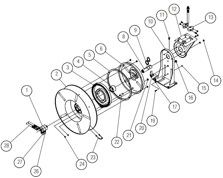
| Item # | Description | # Req. | TW7400 OLPT | TW7450 OLPT | TW7460 OLP | TW7460 OLPT | SW7650 OLPT |
| 1 | Swivel Assembly | 1 | S260057-1 | S260057-1 | S260057-3 | S260057-1 | 602844-1 |
| 2 | Sheave Assembly | 1 | S260011 | S260011 | S260011 | S260011 | S260011 |
| 3 | Drive Spring Assembly | 1 | S260028 | S260028 | S260028 | S260028 | S260028 |
| 4 | Spring Arbor Kit | 1 | S600621 | S600621 | S600621 | S600621 | S600621 |
| 5 | Gasket | 1 | S260069 | S260069 | S260069 | S260069 | S260069 |
| 6 | Springcase Assembly | 1 | S260074 | S260074 | S260074 | S260074 | S260074 |
| 8 | Main Shaft | 1 | 602241 | 602241 | 602241 | 602241 | 602231-2 |
| 9 | Snap Ring | 2 | 300007 | 300007 | 300007 | 300007 | 300007 |
| 10 | Base Assembly | 1 | S600016 | S600016 | S600016 | S600016 | S600016 |
| 11 | 1/2-13 Set Screw | 1 | S35-84 | S35-84 | S35-84 | S35-84 | S35-84 |
| 12 | Guide Arm with Rollers | 1 | 600017 | 600017 | 600017 | 600017 | 600017 |
| 13 | Bumper Stop Assembly | 1 | None | 8-HR1004-3 | 8-HR1004-3 | 8-HR1004-3 | 1-HR1004-3 |
| 14 | 5/16-18 Whizloc | 4 | 300107 | 300107 | 300107 | 300107 | 300107 |
| 15 | 10-32 Nyloc Nut | 7 | S82-15 | S82-15 | S82-15 | S82-15 | S82-15 |
| 16 | 1/2-20 Hex Nut | 1 | S280-8 | S280-8 | S280-8 | S280-8 | S280-8 |
| 17 | Latch Spring | 1 | S260067-1 | S260067-1 | S260067-1 | S260067-1 | S260067-1 |
| 19 | 10-32 Shoulder Screw | 1 | S393-2 | S393-2 | S393-2 | S393-2 | S393-2 |
| 20 | Latch Pawl Assembly | 1 | S600018 | S600018 | S600018 | S600018 | S600018 |
| 21 | 3/8-24 Jam Nut | 1 | S76-106 | S76-106 | S76-106 | S76-106 | S76-106 |
| 22 | Spring Case Stud | 1 | S260031 | S260031 | S260031 | S260031 | S260031 |
| 23 | U-bolt | 1 | 5-117440 | 5-117440 | 5-117440 | 5-117440 | 5-117440 |
| 24 | 1/4-20 Nyloc Nut | 2 | 261650-1 | 261650-1 | 261650-1 | 261650-1 | 261650-1 |
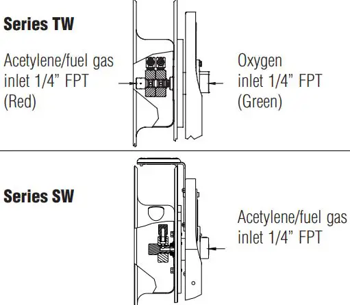
| 26 | 90° Ell (Oxygen) | 1 | S300091 | S300091 | S300091 | S300091 | None |
| 27 | 90° Ell Acetylene/Fuel | 1 | S300090 | S300090 | S300090 | S300090 | 262027 |
| 28 | Hose Assembly | 1 | None | 601031-50 | 601032-60 | 601031-60 | 601163-50 |
| Hose I.D. x Length | None | 1/4” x 50’ | 1/4” x 60’ | 1/4” x 60’ | 3/8” x 50’ | ||
| Reel Inlet Connection | 1/4” NPT(F) | 1/4” NPT(F) | 1/4” NPT(F) | 1/4” NPT(F) | 3/8” NPT(F) | ||
| Max. Operating Pressure | 200 PSI | 200 PSI | 200 PSI | 200 PSI | 200 PSI | ||
| Max. Operating Temperature | 150 °F | 150 °F | 150 °F | 150 °F | 150 °F | ||


