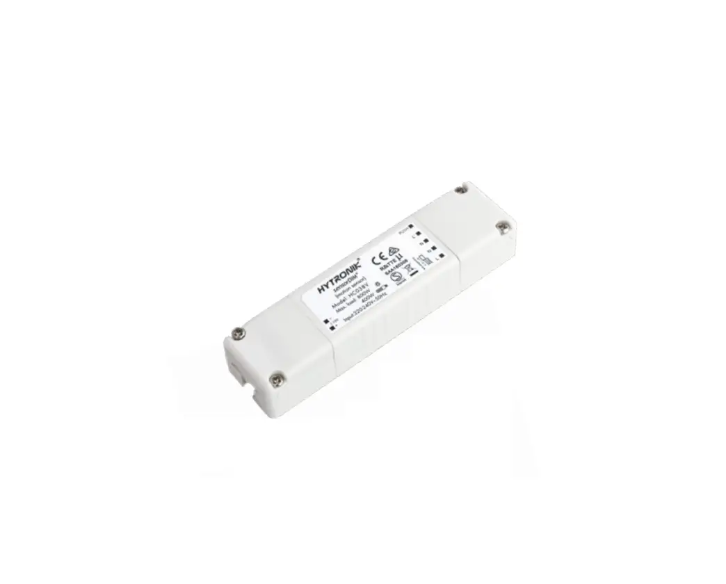
HYTRONIK HC038V Tri-level Control and Daylight Harvest PIR Sensor
Product Description
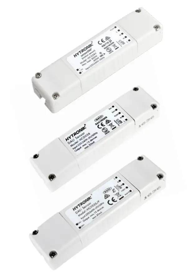
HC038V is a 1-10V control base whereas HCD038 and HCD038/P are DALI control bases with 30mA DALI power supply built in. They work with a wide range of microwave and PIR sensor heads. They are ideal for metal luminaire designs because the Bluetooth module is placed inside the sensor heads instead of control base, so that the Bluetooth signal transmission is viable. They are suitable for any typical indoor applications such as office, classroom, car park, warehouse and other commercial/industrial areas. With Bluetooth wireless mesh networking, it makes communication much easier without any hardwiring, which eventually adds values to luminaires and saves costs for projects. Meanwhile, simple device setup and commissioning can be done via app
App Features
 | Quick setup mode & advanced setup mode |
 | Web app/platform for project deployment & data analysis |
 | Koolmesh Pro app on iPad for on-site conguration |
 | Floorplan feature to simplify project planning |
 | DALI-2 and D4i supported coming soon |
 | One-key device replacement |
 | Device social relations check |
 | Staircase function (primary & secondary) |
 | Remote control via gateway support HBGW01 |
 | Heat map |
 | Dynamic daylight harvest auto-adaptation |
 | Grouping luminaires via mesh network |
 | Scenes |
 | Dusk/Dawn photocell (Twilight function) |
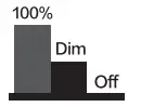 | Tri-level control |
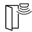
 | Daylight harvest |
 | Push switch conguration |
 | Detailed motion sensor settings |
 | Schedule |
 | Astro timer (sunrise and sunset) |
 | Power-on status (memory against power loss) |
 | Offline commissioning |
 | Bulk commissioning (copy and paste settings) |
 | Different permission levels via authority management |
 | Network sharing via QR code or keycode |
 | Interoperability with Hytronik Bluetooth product portfolio |
 | Compatible with EnOcean BLE switches |
 | Internet-of-Things (IoT) featured |
| Device rmware update over-the-air (OTA) |
 | Continuous development in progress… |

Hardware Features
| HC038V:1-10V output with 400VA (capacitive) & 800W (resistive) |
 | HCD038& HCD038/P: 30mA DALI broadcast output for up to 15 LED drivers |
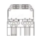 | Plug’n’Play for ‑exible installation and cost saving assemble |
 | Support to control DT8 LED drivers (HCD038 and HCD038/P) |
 | 2 Push inputs for ‑exible manual control (HCD038/P only) |
 | Zero crossing detection circuit to reduce in-rush current and prolong relay lifetime (HC038V only) |
 | Loop-in and loop-out terminals for efcient installation (HC038V only) |
 | 5-year warranty |
 | |
 |
|
Smartphone app for both iOS & Android platform | |
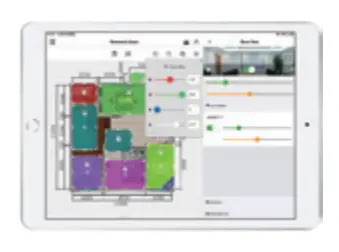 |  |
Koolmesh Pro app for iPad | |
 |  |
Web app/platform: www.iot.koolmesh.com | |

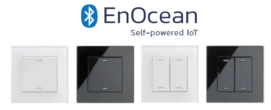
Fully support EnOcean self-powered switch module PTM215B (HBES01/W & HBES01/B)
Technical Specifications
| Input & Output Characteristics | |
| Operating voltage | 220~240VAC 50/60Hz |
| Stand-by power | <0.5W |
| Load ratings: | |
| HC038V | 400VA (capacitive) 800W (resistive) |
| HCD038 HCD038/P | 30mA (max. 15 devices) |
| Warming-up | 20s |
| Safety & EMC | |
| EMC standard (EMC) | EN55015, EN61000, EN61547 |
| Safety standard (LVD) | EN60669-1/-2-1, AS/NZS60669-1/-2-1 |
| Radio Equipment (RED) | EN300440, EN301489-1/-3/-17 EN62479, EN300328 |
| Certification | Semko, CB, CE , EMC, RED, RCM |
| Environment | |
| Operation temperature | Ta: -20°C ~ +55°C |
| Case temperature (Max.) | Tc: +75°C |
| IP rating | IP20 |
Mechanical Structure & Dimensions
HC038V (1-10V output with 1 push)
HCD038 (DALI output with 1 push)
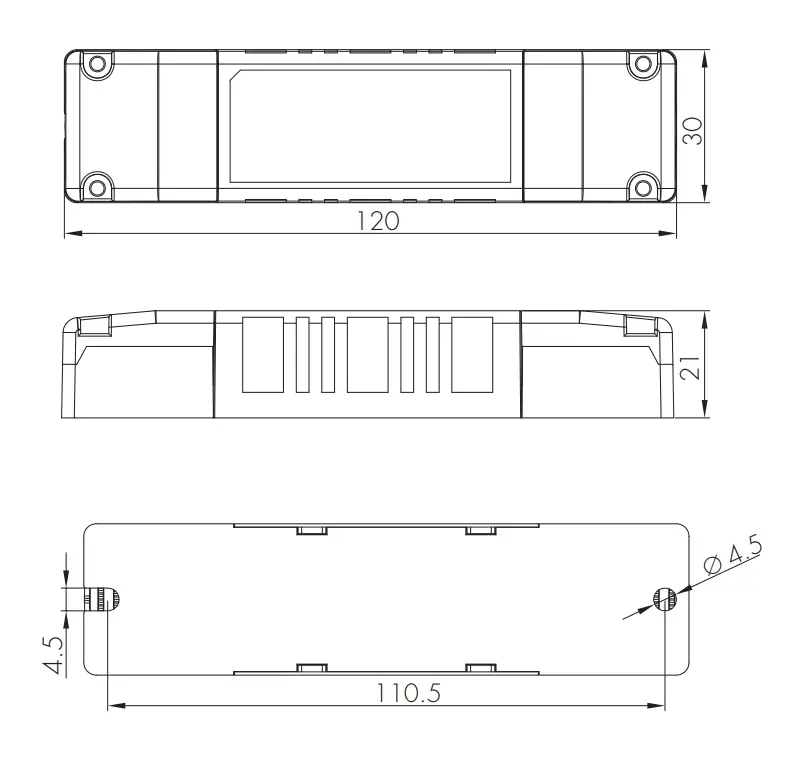
HCD038/P (DALI output with 2 push)
Wire Preparation
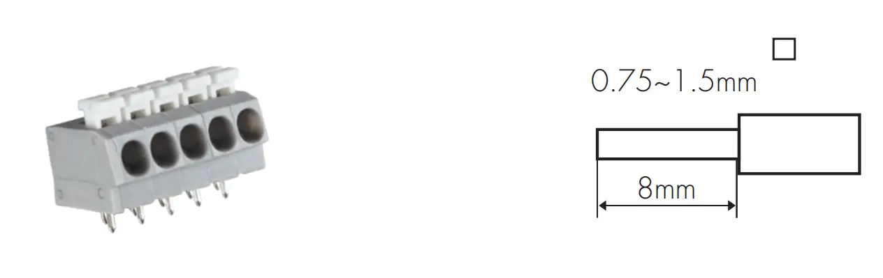
To make or release the wire from the terminal, use a screwdriver to push down the button.
- 200 metres (total) max. for 1mm² CSA (Ta = 50℃)
- 300 metres (total) max. for 1.5mm² CSA (Ta = 50℃)
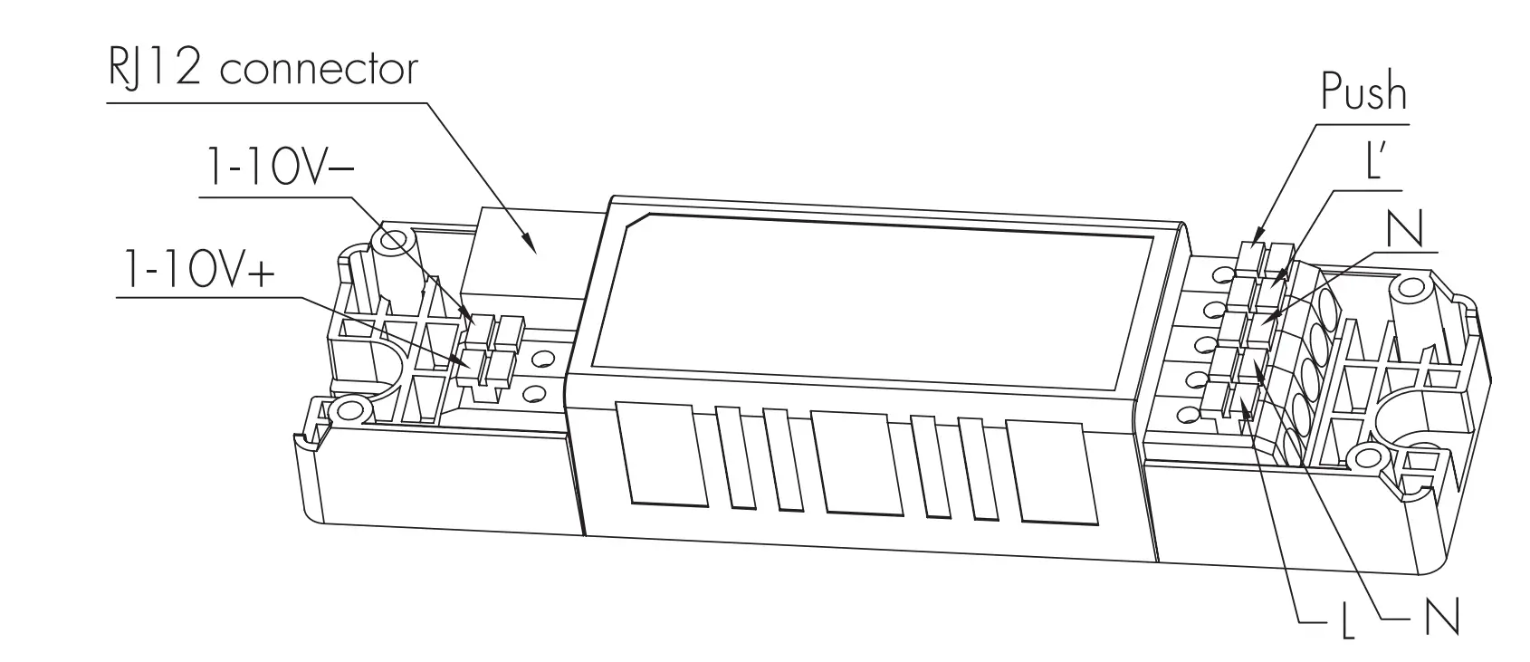
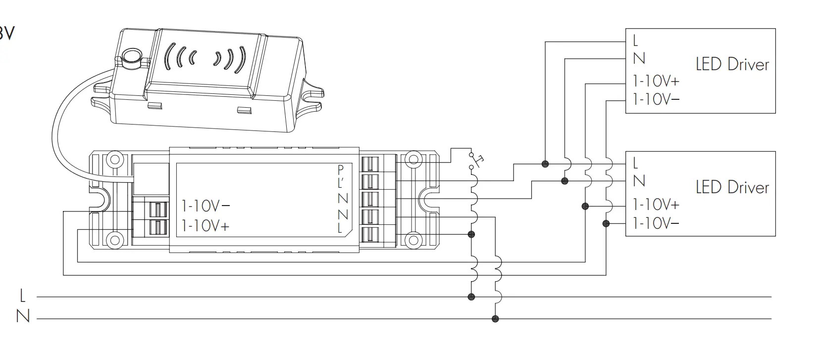
Wiring Diagram
HC038V
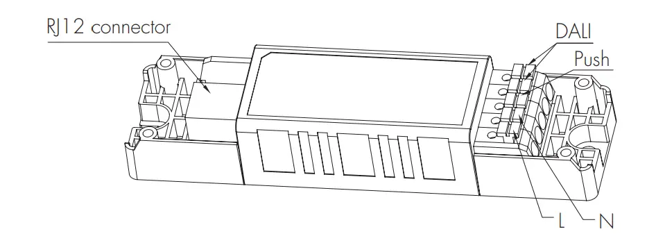
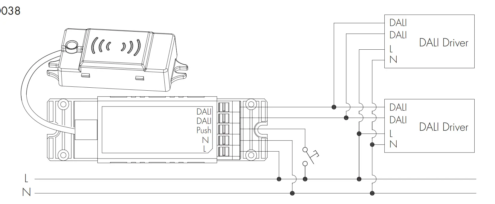
HCD038
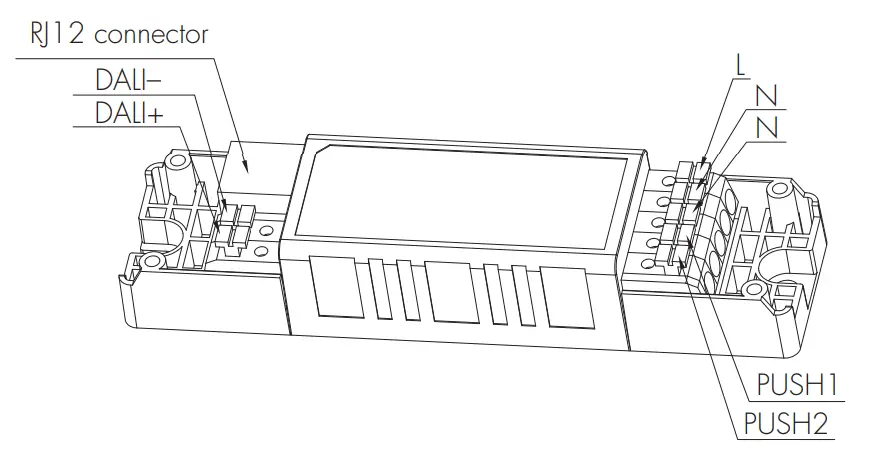
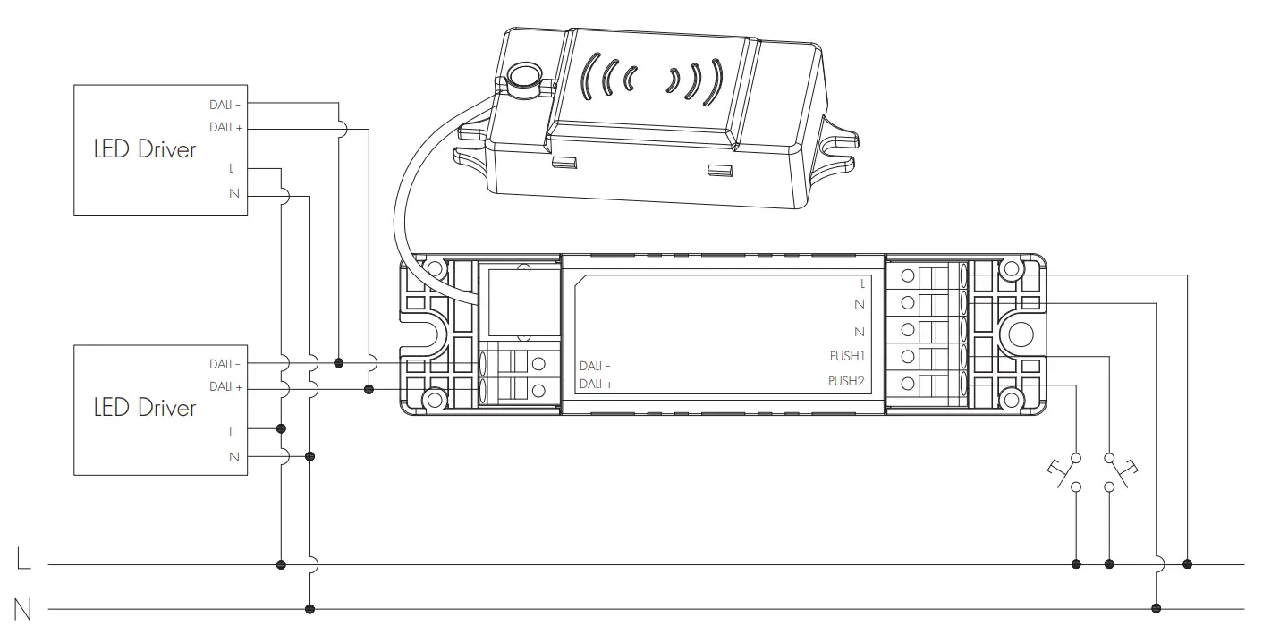
HCD038/P
Technical Specifications for Sensor Heads
| Bluetooth Transceiver | |
| Operation frequency | 2.4 GHz – 2.483 GHz |
| Transmission powe | 4 dBm |
| Range (Typical indoor | 10~30m |
| Protocol | |
| Environment | |
| Operation temperature | Ta: -20°C ~ +55°C |
| Storage temperature | -20OC ~ +70OC |
| Relative humidity | 0 ~ 90% |
| IP rating | IP20 |
| HF Sensor Properties (HBT01) | |
| Sensor principle | High Frequency (microwave) |
| Operation frequency | 5.8GHz +/- 75MHz |
| Transmission power | <0.2mW |
| Detection range* | Max installation height:3m Max detection range (Ø):8m |
| Detection angle | 30O ~ 150O |
| PIR Sensor Properties (HIR13 & HIR16 & HIR62 & HIR62/R) | |
| Sensor principle | PIR detection |
| Operation voltage | 5VDC |
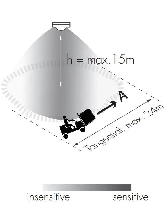
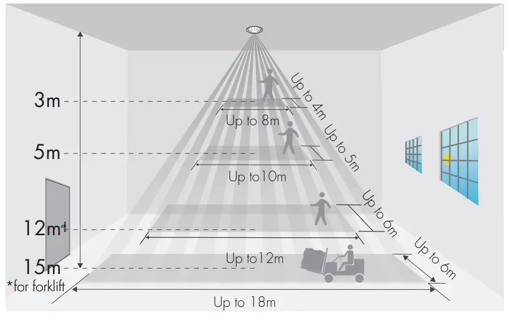
| Detection range * | HIR13 Max installation height:15m (forklift) 12m (single person) Max detection range (Ø):24mHIR16 Max installation height:15m (forklift) 12m (single person) Max detection range: 18m * 6m (L * W) HIR62 HIR62/R Max installation height:8m (single person) Max installation height:12m (forklift) Max detection range (Ø):14m |
| Detection angle | 360° |
- The detection range is heavily inuenced by sensor placement (angle) and different walking paces. It may be reduced under certain conditions.
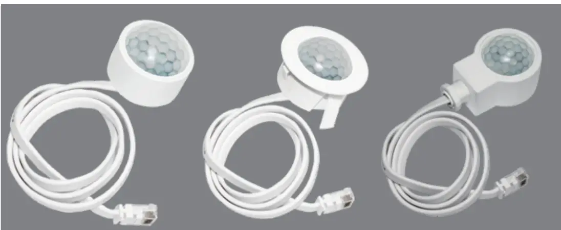
PIR & microwave sensor heads
The range of PIR and microwave sensor heads below with Bluetooth modules built in offers powerful number of Plug’n’Play feature options to expand the fiexibility of luminaires design. This approach to luminaire design reduces space requirements and component costs whilst simplifying production.
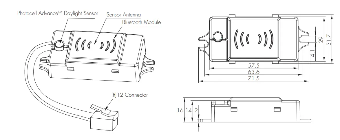
A. HBT01
Surface mounting Photocell AdvanceTM The cable length is around 30cm.
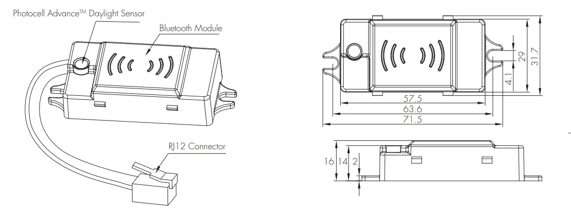
B. HBT02
Surface mounting Without motion sensor Photocell AdvanceTM The cable length is around 30cm.
C. HIR13/S
Surface mounting For highbay application IP65 (facia / lens part) The cable length is around 30cm
D. HIR13/F
Flush mounting For highbay application IP65 (facia / lens part) The cable length is around 30cm.
E.HIR13/C
Screw to the luminaire by conduit For highbay application IP65 (facia / lens part) The cable length is around 30cm.
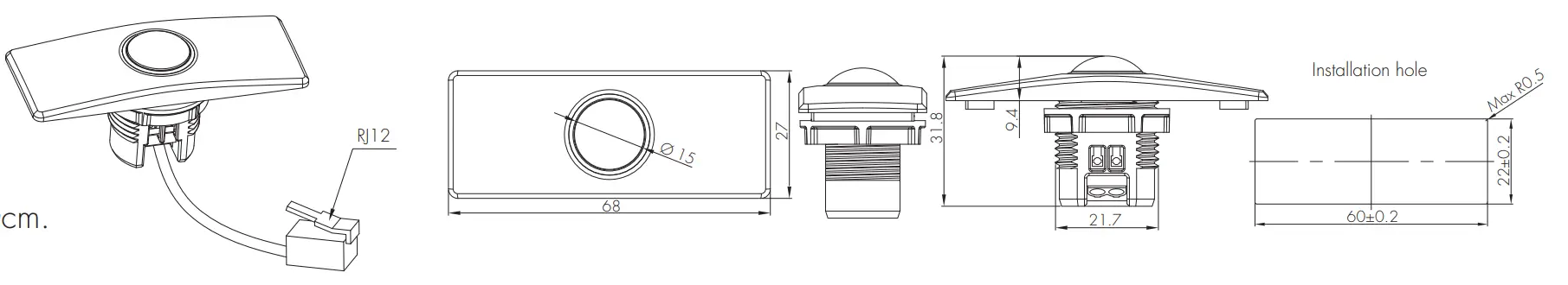
F.HIR16
PIR sensor head For highbay application IP65 (facia / lens part) The cable length is around 30cm.
Installation for HIR16

We suggest that the metal plate thickness to be 0.8mm – 1.6mm to ensure perfect focal length for the PIR lens.
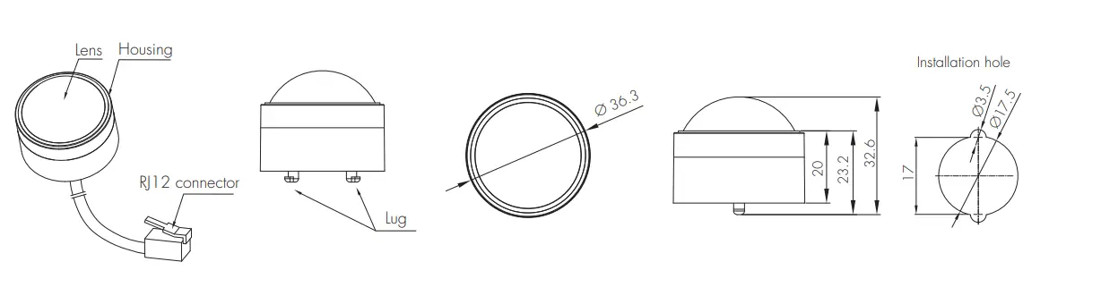
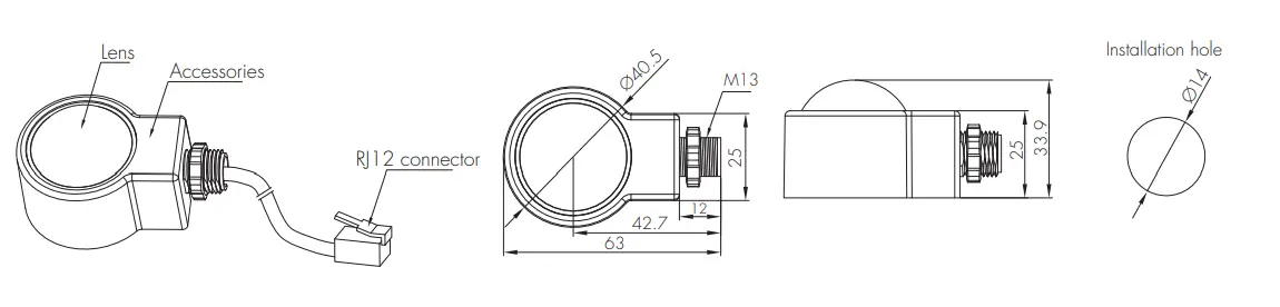
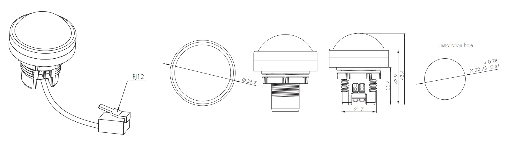
G. HIR62
PIR sensor head The cable length is around 30cm.
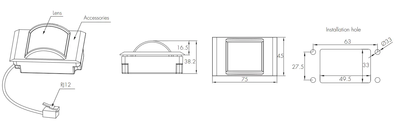
H. HIR62 with HA04
PIR sensor head Optional accessory The cable length is around 30cm.
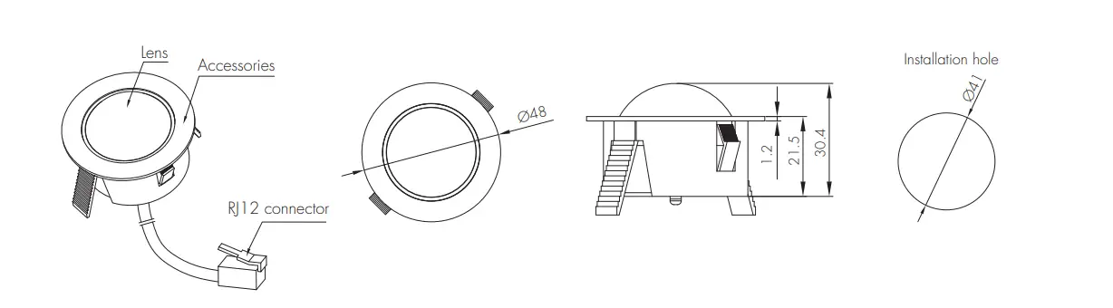
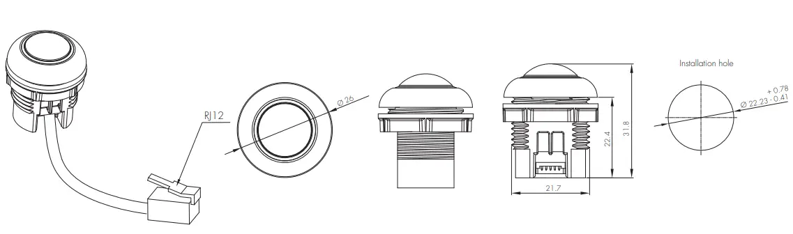
I. HIR62 with HA05
PIR sensor head Optional accessory The cable length is around 30cm.
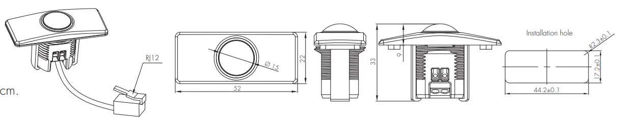
J. HIR62/R
PIR sensor head IP65 (facia / lens part) The cable length is around 30cm.
Note: When HIR62 or HIR62/R plug with HCD038/P, only one push terminal can be activated for conguration.
Detection Pattern
HIR13 (High-bay) | |||||
 | HIR13: High-bay lens detection pattern for forklift @ Ta = 20OC (Recommended installation height 10m-15m) | ||||
 | 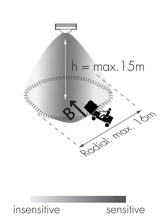 | Mount height | Tangential (A) | Radial (B) | |
| 10m | max 380m2 (Ø = 22m) | max 201m2 (Ø = 16m) | |||
| 11m | max 452m2 (Ø = 24m) | max 201m2 (Ø = 16m) | |||
| 12m | max 452m2 (Ø = 24m) | max 201m2 (Ø = 16m) | |||
| 13m | max 452m2 (Ø = 24m) | max 177m2 (Ø = 15m) | |||
| 14m | max 452m2 (Ø = 24m) | max 133m2 (Ø = 13m) | |||
| 15m | max 452m2 (Ø = 24m) | max 113m2 (Ø = 12m) | |||
| HIR13: High-bay lens detection pattern for single person @ Ta = 20 C (Recommended installation height 2.5m-12m) | ||||
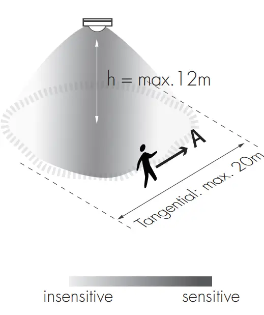 | 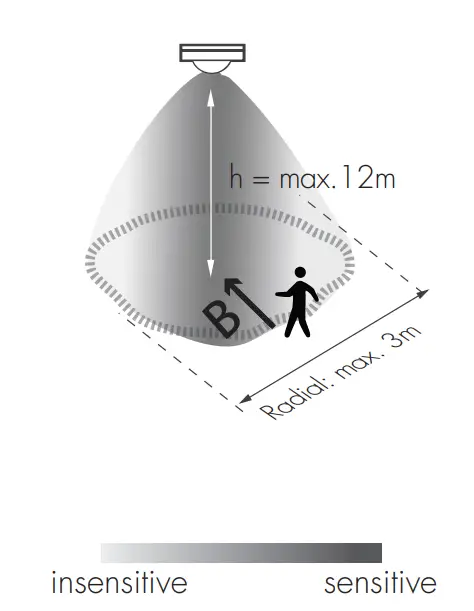 | Mount height | Tangential (A) | Radial (B) | |
| 2.5m | max 50m2 (Ø = 8m) | max 7m2 (Ø = 3m) | |||
| 6m | max 104m2 (Ø = 11.5m) | max 7m2 (Ø = 3m) | |||
| 8m | max 154m2 (Ø = 14m) | max 7m2 (Ø = 3m) | |||
| 10m | max 227m2 (Ø = 17m) | max 7m2 (Ø = 3m) | |||
| 11m | max 269m2 (Ø = 18.5m) | max 7m2 (Ø = 3m) | |||
| 12m | max 314m2 (Ø = 20m) | max 7m2 (Ø = 3m) | |||
HIR16
HIR62
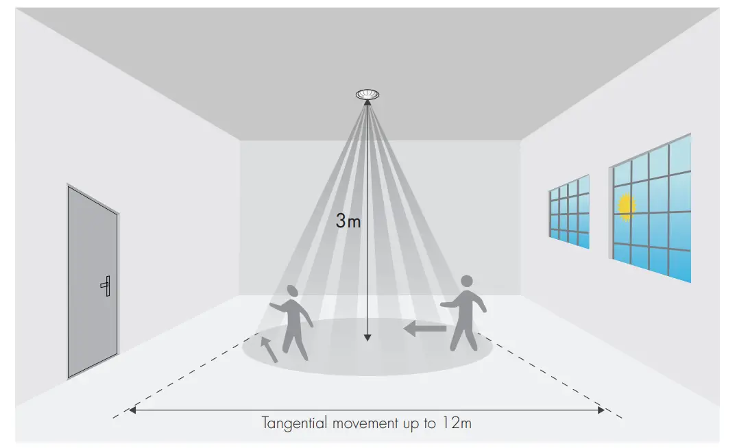
HIR62/R
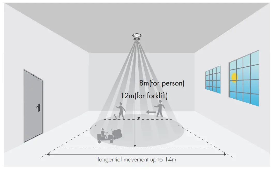
*The detection patterns are based upon 5km/h movement speed.
HBT01
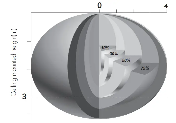
The detection range is heavily inuenced by sensor placement (angle) and different walking paces.
It may be reduced to 2m(diameter) & 3m(height) under certain conditions (walking across).
Dimming Interface Operation Notes
Switch-Dim
The provided Switch-Dim interface allows for a simple dimming method using commercially available non-latching (momentary) wall switches. Detailed Push switch configurations can be set on Koolmesh app.
| Switch Function | Action | Descriptions | |
| Push switch | Short press (<1 second) * Short press has to be longer than 0.1s, or it will be invalid. |
|
|
| Double push |
|
| |
| Long press (≥1 second) |
| ||
Sensor-link | / |
| |
| Emergency Self-Test Function | Short press (<1 second) * Short press has to be longer than 0.1s, or it will be invalid. |
|
|
| Long press (≥1 second) |
|
| |
| Fire Alarm (VFC signal only) | Refer to |
| |
Additional Information / Documents
- For full explanation of Hytronik Photocell AdvanceTM technology, please kindly refer to www.hytronik.com/download ->knowledge ->Introduction of Photocell Advance
- To learn more about detailed product features/functions, please refer to www.hytronik.com/download ->knowledge ->Introduction of App Scenes and Product Functions
- Regarding precautions for Bluetooth product installation and operation, please kindly refer to www.hytronik.com/download ->knowledge ->Bluetooth Products – Precautions for Product Installation and Operation
- Regarding precautions for microwave sensor installation and operation, please kindly refer to www.hytronik.com/download ->knowledge ->Microwave Sensors – Precautions for Product Installation and Operation
- Regarding precautions for PIR Sensors installation and operation, please kindly refer to www.hytronik.com/download ->knowledge ->PIR Sensors – Precautions for Product Installation and Operation
- Data sheet is subject to change without notice. Please always refer to the most recent release on www.hytronik.com/products/bluetooth technology ->Bluetooth Sensors
- Regarding Hytronik standard guarantee policy, please refer to www.hytronik.com/download ->knowledge ->Hytronik Standard Guarantee Policy
![]()