![]()
Kawasaki Mule 600/610
Winch Mount PART # 100575
Kit Components: Hardware Kit: HK-028, HK-031
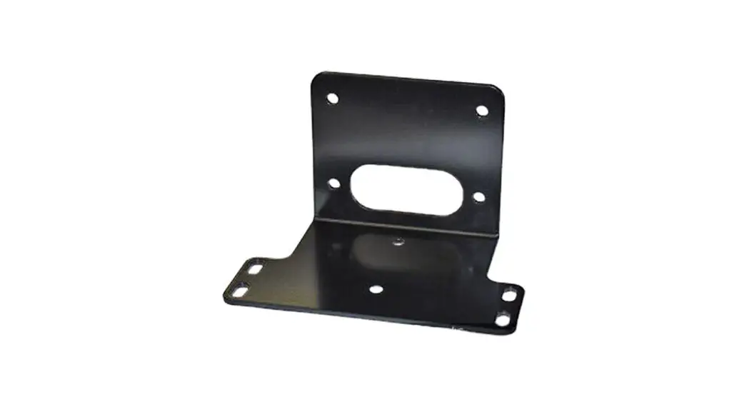
100575 Winch Mount
| Qty | Part Description |
| 1 | Winch Mount |
| 2 | 5/16”-18 x 1-1/4 x 1-3/4” U-Bolt |
| 2 | 5/16”-18 x 1.00” HH Flange Bolt |
| 1 | 5/16”-18 x 1.00” Flat Head Screw |
| 7 | 5/16” Nylock Nuts |
| 7 | 5/16” SAE Flat Washers |
| 1 | HK-031 Rocker Hardware Kit |
4-HOLE MOUNTED WINCH
INSTALLATION INSTRUCTIONS:
- Remove the hardware that secures the front plastic bumper cover and remove the bumper cover. “Figure 1”
 Figure 1 Remove Plastic Bumper Cover
 - Place your winch inside the frame of the UTV as shown in Figure 2.
 Figure 2 Place Winch Inside The UTV Frame
 - Place the mount into location as shown in Figure 3 and loosely attach the supplied U-bolts.
- Attach the top of your winch to the mount and UTV by running the hardware thru the bumper frame holes, the mount plate and into your winch “Figure 3 and 4”.
 Figure 3 Place Mount Into Location and Attach (2 Hole Winch Shown)
 - Attach the bottom of your winch to the mount by running the hardware thru your fairlead, the mount plate and into your winch “Figure 4”.
 Figure 4 Assemble Winch to Mount
 - Using the instructions with your Winch, Wire accordingly.
- Re-install your bumper cover from step 1.
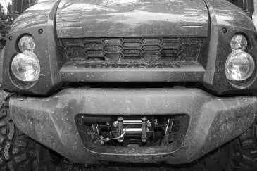 Figure 1 Remove Plastic Bumper Cover
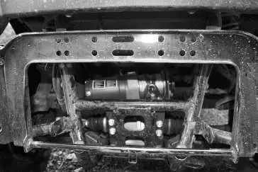 Figure 2 Place Winch Inside The UTV Frame
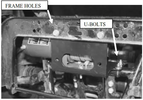 Figure 3 Place Mount Into Location and Attach (2 Hole Winch Shown)
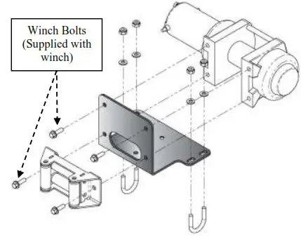 Figure 4 Assemble Winch to Mount
2-HOLE MOUNTED WINCH
- Remove the hardware that secures the front plastic bumper cover and remove the bumper cover. “Figure 1”
- Assemble your fairlead to the mount plate using the hardware that was supplied with you fairlead. “Figure 5”
- Assemble your winch to the mounting plate using our supplied Flat Head Screw in the counter sunk hole and the hardware supplied with your winch in the other bolting location. “Figure 5”
- Place your Winch Assembly into location and mount to your UTV using the supplied 5/16” hardware as shown. “Figures 3 and 5”
- Using the instructions with your Winch, Wire accordingly
- Re-install your bumper cover from step 1.
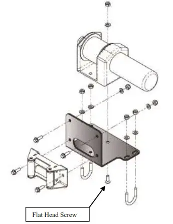
Figure 5 Assemble Winch to the Mount
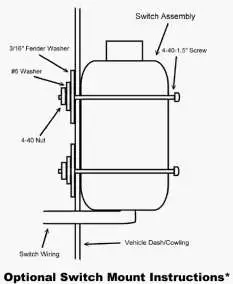
Mini-Rocker Switch Hardware Kit
This allows you to mount your usual handle bar mounted switch to almost any desired location.
a. Remove handlebar mount hardware from the switch.
b. Locate desired mounting location
c. Mark and drill two switch holes through dash using switch housing as a template
d. Drill a 3rd hole for the switch wiring.
e. Assemble per Figure 6
 ©2007 Copyright Kappers Fabricating, Inc.
All rights reserved


