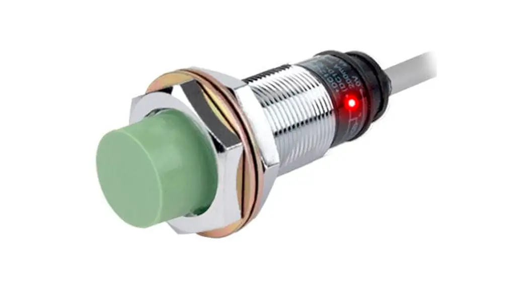
![]() Cylindrical Inductive Long-Distance
Cylindrical Inductive Long-Distance
Proximity Sensors
PRD Series (IO-Link)
INSTRUCTION MANUAL
PDR Series Cylindrical Inductive Long Distance Proximity Sensors
Thank you for choosing our Autonics product.
Read and understand the instruction manual and manual thoroughly before using the product.
For your safety, read and follow the below safety considerations before using.
For your safety, read and follow the considerations written in the instruction manual, other manuals and Autonics website.
Keep this instruction manual in a place where you can find easily.
The specifications, dimensions, etc. are subject to change without notice for product improvement. Some models may be discontinued without notice.
Follow Autonics website for the latest information.
Safety Considerations
- Observe all ‘Safety Considerations’ for safe and proper operation to avoid hazards.
 symbol indicates caution due to special circumstances in which hazards may occur.
![]() Warning Failure to follow instructions may result in serious injury or death.
Warning Failure to follow instructions may result in serious injury or death.
- Fail-safe device must be installed when using the unit with machinery that may cause serious injury or substantial economic loss.(e.g. nuclear power control, medical equipment, ships, vehicles, railways, aircraft, combustion apparatus, safety equipment, crime/disaster prevention devices, etc.)
Failure to follow this instruction may result in personal injury, economic loss or fire. - Do not use the unit in the place where flammable/explosive/corrosive gas, high humidity, direct sunlight, radiant heat, vibration, impact or salinity may be present.
Failure to follow this instruction may result in explosion or fire. - Do not disassemble or modify the unit.
Failure to follow this instruction may result in fire. - Do not connect, repair, or inspect the unit while connected to a power source.
Failure to follow this instruction may result in fire. - Check ‘Connections’ before wiring.
Failure to follow this instruction may result in fire.
![]() Caution Failure to follow instructions may result in injury or product damage.
Caution Failure to follow instructions may result in injury or product damage.
- Use the unit within the rated specifications.
Failure to follow this instruction may result in fire or product damage. - Use a dry cloth to clean the unit, and do not use water or organic solvent.
Failure to follow this instruction may result in fire. - Do not supply power without load.
Failure to follow this instruction may result in fire or product damage.
Cautions during Use
- Follow instructions in ‘Cautions during Use’.
Otherwise, it may cause unexpected accidents. - 2 – 24 VDCᜡ power supply should be insulated and limited voltage/current or Class 2, SELV power supply device.
- Use the product, after 0.8 sec of supplying power.
- Wire as short as possible and keep away from high voltage lines or power lines, to prevent surge and inductive noise.
Do not use near the equipment which generates strong magnetic force or high frequency noise (transceiver, etc.).
In case installing the product near the equipment which generates strong surge (motor, welding machine, etc.), use diode or varistor to remove surge. - This unit may be used in the following environments.
– Indoors (UL Type 1 Enclosure)
– Altitude max. 2,000 m
– Pollution degree 3
– Installation category II
Cautions for Installation
- Install the unit correctly with the usage environment, location, and the designated specifications.
- Do NOT impacts with a hard object or excessive bending of the wire lead-out. It may cause damage the water resistance.
- Do NOT pull the Ø 3.5 mm cable with a tensile strength of 25 N, the Ø 4 mm cable with a tensile strength of 30 N or over and the Ø 5 mm cable with a tensile strength of 50 N or over. It may result in fire due to the broken wire.
- When extending wire, use AWG 22 cable or over within 200 m.
In case of IO-Link mode, the cable length between the unit and the IO-Link Master should be under 20 m.
Ordering Information
This is only for reference, the actual product does not support all combinations.
For selecting the specified model, follow the Autonics website.
- Connection
No mark: Cable type
W: Cable connector type
CM: Connector type - DIA. of sensing side
Number: DIA. of sensing side (unit: mm) - Sensing distance
Number: Sensing distance (unit: mm) - Cable
No mark: Standard type
V: Oil resistant cable type
Product Components
- Product × 1
- Instruction manual × 1
- Nut × 2
- Washer × 1″
Sold Separately
- Connector cable, connector connection cable
- Transmission coupler
- Spatter protection cover
- Fixed bracket
Communication Interface
■ IO-Link
| Version | Ver. 1.1 |
| Class | Class A |
| Baud rate | COM 2 (38.4 kbps) |
| Min. cycle time | 2.3 ms |
| Data length | PD: 2 byte, OD: 1 byte (M-sequence: TYPE_2_2) |
| Vendor ID | 899 (0x383) |
Software
Download the installation file and the manuals from the Autonics website.
■ atIOLink
atIOLink with purposes for setting, diagnosis, and maintenance of IO-Link device via IODD file is provided as the Port and Device Configuration Tool (PDCT).
• IODD (IO Device Description)
This file contains information such as manufacturer information, process data, diagnostic data, and parameter setting of a sensor using IO-Link communication. By uploading the IODD file to PDCT Software, you can check the setting and communication data according to the user interface. Download the IODD file from the Autonics website.
Circuits
- Brown……….. +L
- White……………. I/Q 01)
- Blue………….. L-
- Black…………….. C/Q
01) The I/Q terminal is the inverted output of the C/Q terminal.
■ IO-Link mode
• The control output mode can be switched through parameter setting.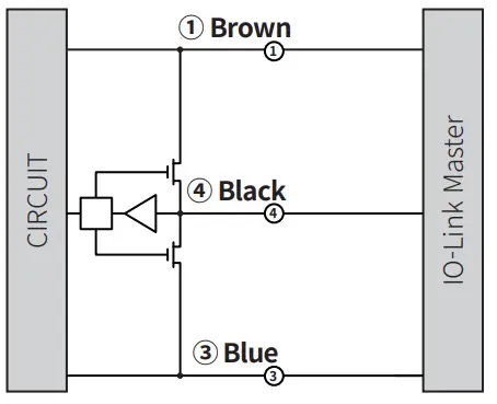 ■ SIO mode
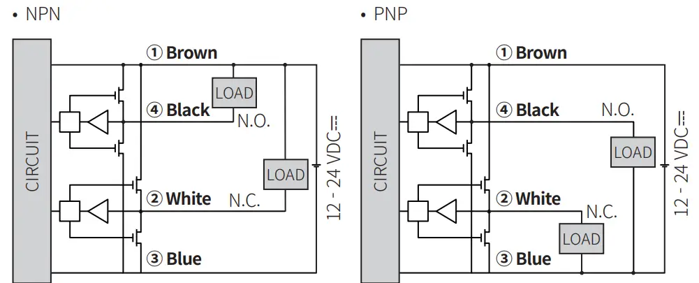
- The control output mode can be selected through load connection.
- Factory default: Black N.O / White N.C.

Connector Specification
- For LOAD connection, follow the cable type connection.
- Fasten the connector not to shown the thread. (0.39 to 0.49 N m)
- Fasten the vibration part with PTFE tape.

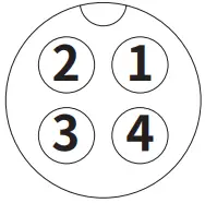
- Brown…………….. +L
- White…………………… I/Q 01)
- Blue…………………… L-
- Black………………… C/Q
01) The I/Q terminal is the inverted output of the C/Q terminal.
Functions
■ Output-related functions
- IO-Link or SIO mode
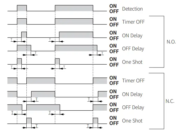
(Parameter setting possible through software when IO-Link mode) - Timer mode (Timer OFF (factory default) / ON Delay / OFF Delay / One Shot)
- Timer time (1 to 9999 ms)
- Too close target detection and unstable detection alarm
- Control output (Push-Pull / NPN / PNP)
- Output mode (N.O. (Normally Open) / N.C. (Normally Closed))
- Operating time save
■ Monitoring functions
- Power monitoring
- Output disconnection detection
- Coil disconnection detection
- Over temperature detection
- Operating time alarm
- Disturbance signal detection
Specifications
| Installation | Flush type | ||
| Model | PRD□12-4D-□-IL2 | PRD□18-7D-□-IL2 | PRD□30-15D-□-IL2 |
| DIA. of sensing side | Ø 12 mm | Ø 18 mm | Ø 30 mm |
| Sensing distance | 4 mm | 7 mm | 15 mm |
| Setting distance | 0 to 2.8 mm | 0 to 4.9 mm | 0 to 10.5 mm |
| Hysteresis | ≤ 10 % of sensing distance | ||
| Standard sensing target: iron | 12 × 12 × 1 mm | 20 × 20 × 1 mm | 45 × 45 × 1 mm |
| Response frequency 01) | 500 Hz | 250 Hz | 100 Hz |
| Affection by temperature | ≤ ± 10 % for sensing distance at ambient temperature 20 ℃ | ||
| Indicator 02) | IO-Link mode, SIO mode | ||
| IO-Link mode | Communication indicator (flashing green), operation indicator (orange), Abnormal detect indicator (cross-flashing green, orange) | ||
| SIO mode | Operation indicator (orange), stable indicator (green), Abnormal detect indicator (cross-flashing green, orange) | ||
| Approval | |||
- The response frequency is the average value. The standard sensing target is used and the width is set as 2 times of the standard sensing target, 1/2 of the sensing distance for the distance.
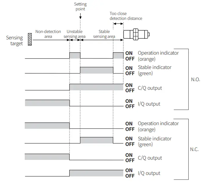
- In case of SIO mode, use the device within the range where the stable indicator (green) is ON.
If the sensing target is in the too close detection distance, the stable indicator turns OFF, but it is in a stable detection state.
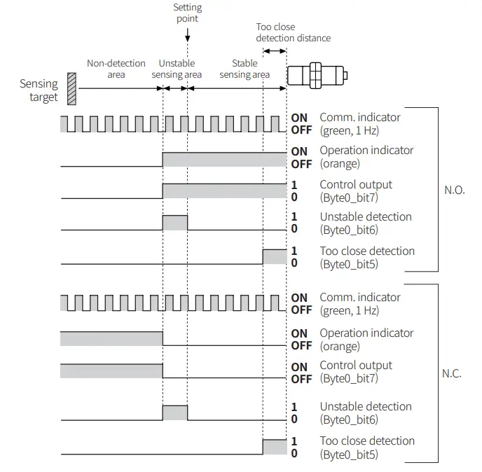
In case of IO-Link mode, use the device within the range where unstable detection (Byte0_bit6) turns 0.
If the sensing target is in the too close detection distance, the too close detection (Byte0_bit5) is 1, but it is a stable detection state.
| Installation | Non-flush type | ||
| Model | PRD□12-8D-□-IL2 | PRD□18-14D-□-IL2 | PRD□30-25D-□-IL2 |
| DIA. of sensing side | Ø 12 mm | Ø 18 mm | Ø 30 mm |
| Sensing distance | 8 mm | 14 mm | 25 mm |
| Setting distance | 0 to 5.6 mm | 0 to 9.8 mm | 0 to 17.5 mm |
| Hysteresis | ≤ 10 % of sensing distance | ||
| Standard sensingtarget: iron | 25 × 25 × 1 mm | 40 × 40 × 1 mm | 75 × 75 × 1 mm |
| Response frequency 01) | 400 Hz | 200 Hz | 100 Hz |
| Affection by temperature | ≤ ± 10 % for sensing distance at ambient temperature 20 ℃ | ||
| Indicator 02) | IO-Link mode, SIO mode | ||
| IO-Link mode | Communication indicator (flashing green), operation indicator (orange), Abnormal detect indicator (cross-flashing green, orange) | ||
| SIO mode | Operation indicator (orange), stable indicator (green), Abnormal detect indicator (cross-flashing green, orange) | ||
| Approval | |||
- The response frequency is the average value. The standard sensing target is used and the width is set as 2 times of the standard sensing target, 1/2 of the sensing distance for the distance.
- In case of SIO mode, use the device within the range where the stable indicator (green) is ON.
If the sensing target is in the too close detection distance, the stable indicator turns OFF, but it is in a stable detection state.
In case of IO-Link mode, use the device within the range where unstable detection (Byte0_bit6) turns 0.
If the sensing target is in the too close detection distance, the too close detection (Byte0_bit5) is 1, but it is a stable detection state.
| Unit weight (package) | o 12 mm | o 18 mm | o 30 mm |
| Cable | ≈ 62 g (≈ 74 g) | ≈ 97 g (≈ 115 g) | ≈ 143 g (≈ 180 g) |
| Cable connector | ≈ 37 g (≈ 67 g) | ≈ 62 g (≈ 80 g) | ≈ 108 g (≈ 145 g) |
| Connector | ≈ 20g (≈ 49 g) | ≈ 41 g (≈ 81 g) | ≈ 138 g (≈ 197 g) |
| Power supply | 12 – 24 VDCᜡ (ripple P-P: ≤ 10 %), operating voltage: 10 – 30 VDCᜡ |
| Current consumption | IO-Link mode: ≤ 25 mA, SIO mode: ≤ 20 mA |
| Control output | ≤ 100 mA |
| Residual voltage 01) | ≤ 2 V |
| Protection circuit | Surge protection circuit, output short over current protection circuit, reverse polarity protection |
| Insulation resistance | ≥ 50 MΩ (500 VDCᜡ megger) |
| Dielectric strength | 1,000 VACᜠ 50 / 60 Hz for 1 min |
| Vibration | 1.5 mm double amplitude at frequency 10 to 55 Hz (for 1 min) in each X, Y, Z direction for 2 hours |
| Shock | 1000 m/s² (≈ 100 G) in each X, Y, Z direction for 3 times |
| Ambient temp. 02) | -25 to 70 ℃, storage: -25 to 70 ℃ (no freezing or condensation) |
| Ambient humi. | 35 to 95 %RH, storage: 35 to 95 %RH (no freezing or condensation) |
| Protection rating | IP67 (IEC standard) |
| Connection | Cable / Cable connector / connector models |
| Cable spec. 03) | DIA. of sensing side Ø 12 mm: Ø 4 mm, 4-wire DIA. of sensing side Ø 18 mm, Ø 30 mm : Ø 5 mm, 4-wire |
| Wire spec. | AWG 22 (0.08 mm, 60-core), insulator diameter: Ø 1.25 mm |
| Connector spec. | M12 plug connector |
| Material | Standard type cable (black): polyvinyl chloride (PVC), Oil resistant cable (gray): polyvinyl chloride (oil resistant PVC), case / nut: nickel plated brass, washer: nickel plated iron, sensing side: PBT |
- Load current: 100 mA, cable length: 2 m
- UL approved surrounding air temperature 40 ℃
- Cable type: 2 m, Cable connector type: 300 mm
Operation Timing Chart
Parameter Index
- Refer to the Setting Distance Formula for the unstable detection area and the too close detection distance.
■ IO-Link mode
- Operates by setting value
 ■ SIO mode
- Operates by factory default
- Unstable sensing area: 70 % of max. sensing distance, too close detection distance: 20 % of max. sensing distance. (factory default)

- Example of timer set
T: Timer time (1 to 9999 ms)
Parameter Index
■ Process data
The current data value is displayed in real time.
| Parameter | Byte0(PD0) | Byte1(PD1) | Format | Setting range | Description |
| Detection Level | – | 0 to 7 | Uinteger | 0 to 255 | Outputs the detection signal value as specific 8 bit. |
| Warning | 4 | – | Boolean | 0: Normal (OFF), 1: Warning (ON) | Outputs diagnosing items defined as dangerous. |
| Target too Close Alarm | 5 | – | Boolean | 0: Not Close, 1: Too Close | Outputs close range detection status. |
| Instability Detection Alarm | 6 | – | Boolean | 0: Stable, 1: Unstable | Outputs instability detection status. |
| Sensor Output | 7 | – | Boolean | 0: OFF, 1: ON | Displays sensor’s output status. (C/Q terminal) |
Identification menu
The device’s manufacturer information and sensor information is displayed.
It includes additionally information of companies and sensors from the IO-Link standard.
| Parameter | Index | Format | R / W | Description |
| Vendor Name | 16 | String | RO | Manufacturer name |
| Vendor Text | 17 | String | RO | Manufacturer description |
| Product Name | 18 | String | RO | Product name |
| Product ID | 19 | String | RO | Product ID |
| Product Text | 20 | String | RO | Product description |
| H/W Version | 22 | String | RO | Hardware version |
| F/W Version | 23 | String | RO | Firmware version |
| Application specific tag | 24 | String | RW | Application program tag |
■ Observation menu
The device setting value is displayed.
| Parameter | Index | R / W | Description | |
| Operating Hours | – | 72 | RO | Sensor operation time |
| Process Data Input | Detection level | 40 | RO | Current value |
| Warning | RO | Warning | ||
| Target too close alarm | RO | Too close detection | ||
| Instability detection alarm | RO | Unstable detection | ||
| Sensor output | RO | Sensor output | ||
■ Parameter menu
Product settings such as output mode and timer can be changed according to the user environment.
| Parameter | Index | Subindex | Format | R /W | Description | Setting range | Factory default | |
| Output Setup | Mode | 64 | 1 | – | RW | Output mode | 0: N.O. (Normally Open), 1: N.C. (Normally Closed) | 0 |
| Type | 2 | – | RW | Output type | 0: Push-Pull, 1: NPN, 2: PNP | 0 | ||
| Timer | Mode | 66 | 1 | – | RW | Timer mode | 0: Timer OFF, 1: ON Delay, 2: OFF Delay, 3: One Shot | 0 |
| Time (ms) | 2 | – | RW | Timer time | 1 to 9,999 ms | 5 ms | ||
| Target too Close | – | 65 | – | – | RW | Margin according to the target material | 0: Disable, 1: Iron 10 %, 2: Iron 20 %, 3: Iron 30 %, 4: SUS 10 %, 5: SUS 20 %, 6: SUS 30 %, 7: Aluminum 10 %, 8: Aluminum 20 % | 2 |
| Instability Detection Alarm | – | 68 | – | – | RW | Output timing when instable detection | 0: 0 ms, 1: 10 ms, 2: 50 ms, 3: 100 ms, 4: 300 ms, 5: 500 ms, 6: 1000 ms | 4 |
| Restore Factory Settings | – | 2 | – | Uinteger | WO | Factory default reset | 130: Restore factory setting | – |
| Data Storage Lock | – | 12 | 2 | Record | RW | Data storage locked between IO-Link Master- Device | 0: false, 1: true | 0 |
■ Diagnosis Menu
The information about problems encountered during sensor operation is displayed.
| Parameter | Index | Format | R / W | Description | |
| Operating Hours | – | 72 | – | RO | Sensor operation time |
| Process Data Input | Detection Level |
40 | Uinteger | RO | Current value |
| Warning | Boolean | RO | Warning | ||
| Target too Close Alarm | Boolean | RO | Too close detection | ||
| Instability Detection Alarm | Boolean | RO | Unstable detection | ||
| Sensor Output | Boolean | RO | Sensor output | ||
| Detailed Device Status | – | 37 | – | RO | Sensor detailed status |
■ Events
When the corresponding error occurs, the abnormal indicator flashes.
Event name | Event code | Type | Description |
| Warning | 6145 (0x1801) | Coil Disconnection | Coil disconnection detection warning |
| 6146 (0x1802) | Short Circuit | Overcurrent detection warning | |
| 6147 (0x1803) | Over Temperature | Overheat detection warning | |
| 6148 (0x1804) | Supply Under Voltage | Low voltage detection warning | |
| 6149 (0x1805) | Operation Time Alarm | Operation time alarm warning | |
| 6150 (0x1806) | Disturbance Error | Disturbance signal detection warning | |
| 6152 (0x1808) | EEPROM Error | EEPROM error warning | |
| Error | 6151 (0x1807) | Parameter Error | Parameter error |
Cut-out Dimensions
Unit: mm, For the detailed drawings, follow the Autonics website.
| o 12 mm | o 18 mm | o 30 mm | |
| Mounting hole (H) | Ø 12.5 +0.5 0 | Ø 18.5 +0.5 0 | Ø 30.5 +0.5 0 |
| TAP | M12×1 | M18×1 | M30×1.5 |
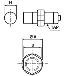
| o 12 mm | o 18 mm | o 30 mm | |
| o A | 21 | 29 | 42 |
| B | 17 | 24 | 35 |
Setting Distance Formula
Detecting distance can be changed by the shape, size or material of the target.
For stable sensing, install the unit within the 70 % of sensing distance.
Setting distance (Sa)
= Sensing distance (Sn) × 70 %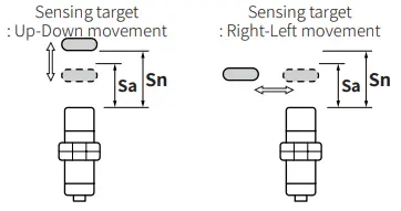 Mutual-interference & Influence by Surrounding Metals
■ Mutual-interference
When plural proximity sensors are mounted in a close row, malfunction of sensor may be caused due to mutual interference.
Therefore, be sure to provide a minimum distance between the two sensors, as below table.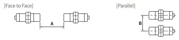 ■ Influence by surrounding metals
When sensors are mounted on metallic panel, it must be prevented sensors from being affected by any metallic object except target. Therefore, be sure to provide a minimum
distance as below chart.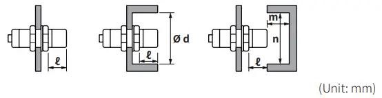
| Sensing side Item | o 12 mm | o 18 mm | o 30 mm | |||
| Flush | Non-flush | Flush | Non-flush | Flush | Non-flush | |
| A | 25 | 120 | 50 | 200 | 110 | 350 |
| B | 25 | 100 | 35 | 110 | 90 | 300 |
| ℓ | 2.5 | 15 | 3.5 | 14 | 6 | 20 |
| o d | 18 | 40 | 27 | 70 | 45 | 120 |
| m | 12 | 20 | 24 | 40 | 45 | 90 |
| n | 18 | 40 | 27 | 70 | 45 | 120 |
Tightening Torque
Use the provided washer to tighten the nuts.
The tightening torque of the nut varies with the distance from the fore-end. [Figure 1]
If the nut tip is located at the front of the product, apply the front tightening torque.
The allowable tightening torque table is for inserting the washer as [Figure 2].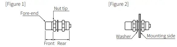
| Sensing side Strength | o 12 mm | o 18 mm | o 30 mm | |||
| Flush | Non-flush | Flush | Non-flush | Flush | Non-flush | |
| Front size | 13 mm | 7 mm | – | – | 26 mm | 12 mm |
| Front torque | 6.37 N m | 14.7 N m | 49 N m | |||
| Rear torque | 11.76 N m | 14.7 N m | 78.4 N m | |||
![]() 18, Bansong-ro 513Beon-gil, Haeundae-gu, Busan, Republic of Korea, 48002
18, Bansong-ro 513Beon-gil, Haeundae-gu, Busan, Republic of Korea, 48002
www.autonics.com | +82-2-2048-1577 | [email protected]

 Cylindrical Inductive Proximity Sensors Instruction Manual")


 Rectangular Flat Type Inductive Proximity Sensors Instruction Manual")


