
Autonics PR Series (DC 3-wire) Cylindrical Inductive Proximity Sensors
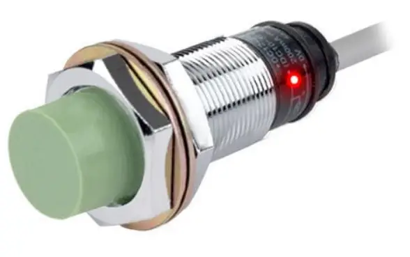
Cylindrical Inductive Proximity Sensors
Product Information
The Cylindrical Inductive Proximity Sensors are part of the PR Series and operate on DC 3-wire. They are available in general-type and spatter-resistant type variants, with different sensing distances and body lengths. The sensing distance ranges from 1.5mm to 10mm, and the body length ranges from normal to short and long. The sensors come with different control output options including NPN normally open, NPN normally closed, PNP normally open, and PNP normally closed. The sensors are not suitable for locations where flammable/explosive/corrosive gas, high humidity, direct sunlight, radiant heat, vibration, impact, or salinity may be present. They should only be used within the rated specifications to avoid any damage or fire hazards. Do not disassemble or modify the unit, and do not connect, repair, or inspect it while connected to a power source. Use a dry cloth to clean the unit and do not use water or organic solvent. Ensure that fail-safe devices are installed when using the sensors with machinery that may cause serious injury or substantial economic loss.
Product Usage Instructions
- Before starting any installation or wiring, check the connections.
- Follow the ordering information on the Autonics website to select the specified model.
- Use the sensors only within the rated specifications to avoid any damage or fire hazards.
- Do not use the sensors in locations where flammable/explosive/corrosive gas, high humidity, direct sunlight, radiant heat, vibration, impact, or salinity may be present.
- Do not disassemble or modify the unit, and do not connect, repair, or inspect it while connected to a power source.
- Use a dry cloth to clean the unit and do not use water or organic solvent.
- Ensure that fail-safe devices are installed when using the sensors with machinery that may cause serious injury or substantial economic loss.
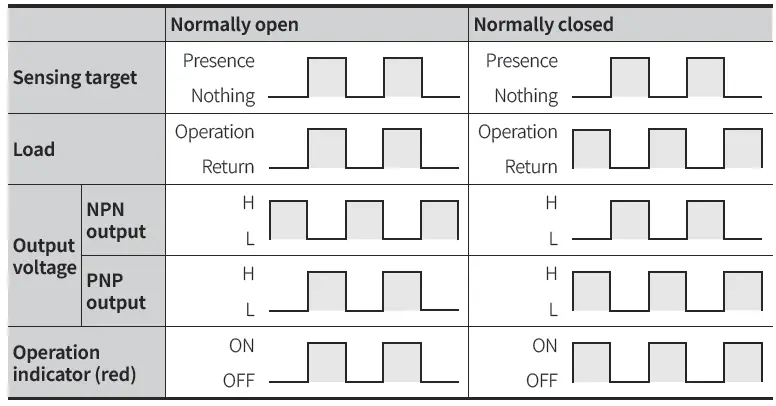
- Refer to the operation timing chart in the user manual to understand the sensor’s behavior.
Thank you for choosing our Autonics product. Read and understand the instruction manual and manual thoroughly before using the product. For your safety, read and follow the below safety considerations before using. For your safety, read and follow the considerations written in the instruction manual, other manuals and Autonics website. Keep this instruction manual in a place where you can find easily. The specifications, dimensions, etc. are subject to change without notice for product improvement. Some models may be discontinued without notice. Follow Autonics website for the latest information.
Safety Considerations
- Observe all ‘Safety Considerations’ for safe and proper operation to avoid hazards.
 symbol indicates caution due to special circumstances in which hazards may occur.
Warning Failure to follow instructions may result in serious injury or death.
- Fail-safe device must be installed when using the unit with machinery that may cause serious injury or substantial economic loss. (e.g. nuclear power control, medical equipment, ships, vehicles, railways, aircraft, combustion apparatus, safety equipment, crime/disaster prevention devices, etc.) Failure to follow this instruction may result in personal injury, economic loss or fire.
- Do not use the unit in the place where flammable/explosive/corrosive gas, high humidity, direct sunlight, radiant heat, vibration, impact, or salinity may be present. Failure to follow this instruction may result in explosion or fire.
- Do not disassemble or modify the unit. Failure to follow this instruction may result in fire.
- Do not connect, repair, or inspect the unit while connected to a power source. Failure to follow this instruction may result in fire.
- Check ‘Connections’ before wiring. Failure to follow this instruction may result in fire.
Caution Failure to follow instructions may result in injury or product damage
- Use the unit within the rated specifications. Failure to follow this instruction may result in fire or product damage.
- Use a dry cloth to clean the unit, and do not use water or organic solvent. Failure to follow this instruction may result in fire.
Cautions during Use
- Follow instructions in ‘Cautions during Use’. Otherwise, it may cause unexpected accidents.
- 12-24 VDC power supply should be insulated and limited voltage/current or Class 2, SELV power supply device.
- Use the product, after 0.8 sec of supplying power.
- Wire as short as possible and keep away from high voltage lines or power lines, to prevent surge and inductive noise. Do not use near the equipment which generates strong magnetic force or high frequency noise (transceiver, etc.). In case installing the product near the equipment which generates strong surge (motor, welding machine, etc.), use diode or varistor to remove surge.
- If the surface is rubbed with a hard object, PTFE coating can be worn out.This unit may be used in the following environments.
- Indoors (in the environment condition rated in ‘Specifications’)
- Altitude max. 2,000 m
- Pollution degree 2
- Installation category II
Cautions for Installation
- Install the unit correctly with the usage environment, location, and the designated specifications.
- Do NOT impacts with a hard object or excessive bending of the wire lead-out. It may cause damage the water resistance.
- Do NOT pull the Ø 3.5 mm cable with a tensile strength of 25 N, the Ø 4 mm cable with a tensile strength of 30 N or over and the Ø 5 mm cable with a tensile strength of 50 N or over. It may result in fire due to the broken wire.
- When extending wire, use AWG 22 cable or over within 200 m.
Ordering Information
This is only for reference, the actual product does not support all combinations. For selecting the specified model, follow the Autonics website

- Characteristic
- No mark: General type
- A: Spatter-resistant type
- Connection
- No mark: Cable type
- W: Cable connector type
- CM: Connector type
- Body length
- No mark: Normal
- S: Short
- L: Long
- DIA. of sensing side
Number: DIA. of sensing side (unit: mm) - Sensing distance
Number: Sensing distance (unit: mm) - Control output
- N: NPN Normally open
- N2: NPN Normally closed
- P: PNP Normally open
- P2: PNP Normally closed
- Cable
- No mark: Standard type
- V: Oil resistant cable type
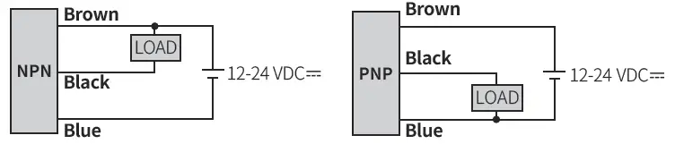
Connections
Cable type
Cable connector type / Connector type
- For LOAD connection, follow the cable type connection.
- Fasten the connector not to shown the thread. (0.39 to 0.49 N m)
- Fasten the vibration part with PTFE tape.
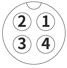
| Pin | Color | Function |
| ① | Brown | +V |
| ② | – | – |
| ③ | Blue | 0 V |
| ④ | Black | OUT |
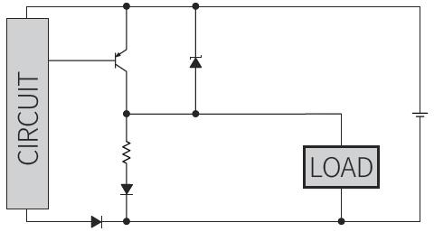
Inner circuit (NPN output)
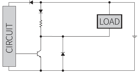
Inner circuit (PNP output)
Operation Timing Chart
 Sold Separately
- Connector cable, connector connection cable
- Transmission coupler
- Spatter protection cover
- Fixed bracket
Specifications
| Installation | Flush type | |||
| General | PR□08-1.5D▭ | PR□12-2D▭ | PR□18-5D▭ | PR□30-10D▭ |
| Spatter- resistant | – | PRA□12-2D▭ | PRA□18-5D▭ | PRA□30-10D▭ |
| DIA. of sensing side | Ø 8 mm | Ø 12 mm | Ø 18 mm | Ø 30 mm |
| Sensing distance | 1.5 mm | 2 mm | 5 mm | 10 mm |
| Setting distance | 0 to 1.05 mm | 0 to 1.4 mm | 0 to 3.5 mm | 0 to 7 mm |
| Hysteresis | ≤ 10 % of sensing distance (DIA. of sensing side Ø 8 mm connector type: ≤ 15 %) | |||
| Standard sensing target: iron | 8 × 8 × 1 mm | 12 × 12 × 1 mm | 18 × 18 × 1 mm | 30 × 30 × 1 mm |
| Response frequency 01) | 1.5 kHz | 1.5 kHz | 500 Hz | 400 Hz |
| Affection by temperature | ≤ ± 10 % for sensing distance at ambient temperature 20 ℃ (DIA. of sensing side Ø 8 mm: ≤ ± 20 %) | |||
| Indicator | Operation indicator (red) | |||
| Approval | ᜢ ᜫ | ᜢ ᜫ | ᜢ ᜫ | ᜢ ᜫ |
| Installation | Non-flush type | |||
| General | PR□08-2D▭ | PR□12-4D▭ | PR□18-8D▭ | PR□30-15D▭ |
| DIA. of sensing side | Ø 8 mm | Ø 12 mm | Ø 18 mm | Ø 30 mm |
| Sensing distance | 2 mm | 4 mm | 8 mm | 15 mm |
| Setting distance | 0 to 1.4 mm | 0 to 2.8 mm | 0 to 5.6 mm | 0 to 10.5 mm |
| Hysteresis | ≤ 10 % of sensing distance (DIA. of sensing side Ø 8 mm connector type: ≤ 15 %) | |||
| Standard sensing target: iron | 8×8×1 mm | 12×12×1 mm | 25×25×1 mm | 45×45×1 mm |
| Response frequency 01) | 1.0 kHz | 500 Hz | 350 Hz | 200 Hz |
| Affection by temperature | ≤ ± 10 % for sensing distance at ambient temperature 20 ℃ (DIA. of sensing side Ø 8 mm: ≤ ± 20 %) | |||
| Indicator | Operation indicator (red) | |||
| Approval | ᜢ ᜫ | ᜢ ᜫ | ᜢ ᜫ | ᜢ ᜫ |
The response frequency is the average value. The standard sensing target is used and the width is set as 2 times of the standard sensing target, 1/2 of the sensing distance for the distance
| Unit weight (package) | Ø 8 mm | Ø 12 mm | Ø 18 mm | Ø 30 mm | |
| Cable | Normal | ≈ 52 g (≈ 64 g) | ≈ 72 g (≈ 84 g) | ≈ 110 g (≈ 122 g) | ≈ 170 g (≈ 207 g) |
| Short | – | ≈ 70 g (≈ 82 g) | – | – | |
| Long | ≈ 54 g (≈ 66 g) | ≈ 76 g (≈ 88 g) | ≈ 130 g (≈ 142 g) | ≈ 210 g (≈ 247 g) | |
| Cable connector | Normal | ≈ 32 g (≈ 44 g) | ≈ 42 g (≈ 54 g) | ≈ 58 g (≈ 70 g) | ≈ 122 g (≈ 134 g) |
| Long | ≈ 34 g (≈ 46 g) | – | ≈ 78 g (≈ 90 g) | ≈ 158 g (≈ 195 g) | |
| Connector | Normal | ≈ 10 g (≈ 32 g) | ≈ 26 g (≈ 38 g) | ≈ 49 g (≈ 61 g) | ≈ 134 g (≈ 146 g) |
| Long | – | – | ≈ 73 g (≈ 85 g) | ≈ 169 g (≈ 181 g) | |
| Power supply | 12 – 24 VDCᜡ (ripple P-P: ≤ 10 %), operating voltage: 10 – 30 VDCᜡ |
| Current consumption | ≤ 10 mA |
| Control output | ≤ 200 mA |
| Residual voltage | DIA. of sensing side Ø 8 mm: ≤ 2.0 V DIA. of sensing side Ø 12 mm, Ø 18 mm, Ø 30 mm: ≤ 1.5 V |
| Protection circuit | Surge protection circuit, output short over current protection circuit, reverse polarity protection |
| Insulation resistance | ≥ 50 MΩ (500 VDCᜡ megger) |
| Dielectric strength | 1,500 VACᜠ 50 / 60Hz for 1 min (between all terminals and case) |
| Vibration | 1 mm double amplitude at frequency 10 to 55 Hz (for 1 min) in each X, Y, Z direction for 2 hours |
| Shock | 500 m/s² (≈ 50 G) in each X, Y, Z direction for 3 times |
| Ambient temperature | -25 to 70 ℃, storage: -30 to 80 ℃ (no freezing or condensation) |
| Ambient humidity | 35 to 95 %RH, storage: 35 to 95 %RH (no freezing or condensation) |
| Protection structure | IP67 (IEC standards) |
| Connection | Cable type / Cable connector type 01) / Connector type model |
| Cable spec. 02) | DIA. of sensing side Ø 8 mm: Ø 3.5 mm, 3-wire DIA. of sensing side Ø 12 mm: Ø 4 mm, 3-wire DIA. of sensing side Ø 18 mm, Ø 30 mm: Ø 5 mm, 3-wire |
| Wire spec. | Ø 3.5 mm cable : AWG 24 (0.08 mm, 40-core), insulator DIA.: Ø 1 mm Ø 4 mm, Ø 5 mm cable : AWG 22 (0.08 mm, 60-core), insulator DIA.: Ø 1.25 mm |
| Connector spec. | M12 connector |
| Material | Standard type cable (black): polyvinyl chloride (PVC) Oil resistant cable (gray): polyvinyl chloride (oil resistant PVC) |
| General | Case/Nut: nickel plated brass (DIA. of sensing side Ø 8 mm connector type case: SUS303), washer: nickel plated iron, sensing side: PBT |
| Spatter-resistant | Case/Nut: PTFE coated brass, washer: PTFE coated iron, sensing side: PTFE |
- Except spatter-resistant type
- Cable type: 2 m, cable connector type: 300 mm
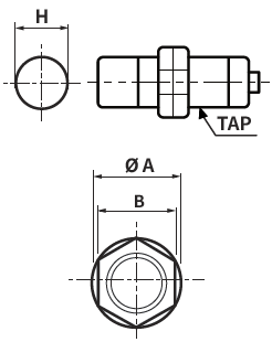
Cut-out Dimensions
Unit: mm, For the detailed drawings, follow the Autonics web site.
| Ø 8 mm | Ø 12 mm | Ø 18 mm | Ø 30 mm | |
| Mounting hole (H) | Ø 8.5 +0.5 0 | Ø 12.5 +0.5 0 | Ø 18.5 +0.5 0 | Ø 30.5 +0.5 0 |
| TAP | M8×1 | M12×1 | M18×1 | M30×1.5 |
| Ø 8 mm | Ø 12 mm | Ø 18 mm | Ø 30 mm | |
| Ø A | 15 | 21 | 29 | 42 |
| B | 13 | 17 | 24 | 35 |
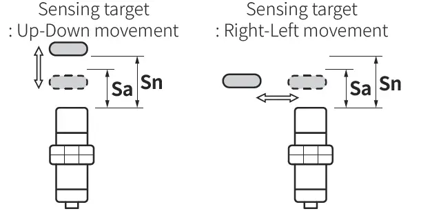
Setting Distance Formula
Detecting distance can be changed by the shape, size or material of the target. For stable sensing, install the unit within the 70 % of sensing distance. Setting distance (Sa) = Sensing distance (Sn) × 70 %
Mutual-interference & Influence by Surrounding Metals
Mutual-interference
When plural proximity sensors are mounted in a close row, malfunction of sensor may be caused due to mutual interference. Therefore, be sure to provide a minimum distance between the two sensors, as below table.
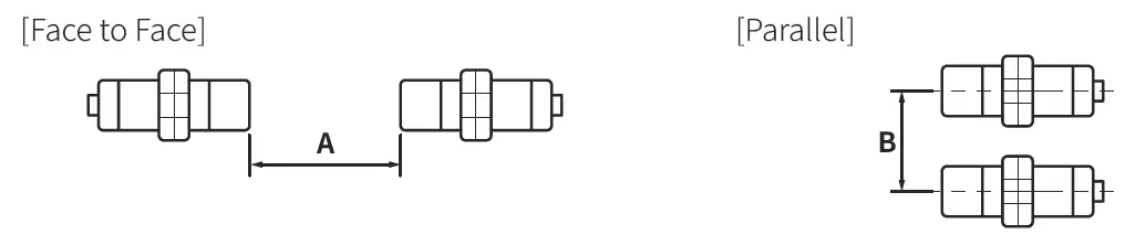
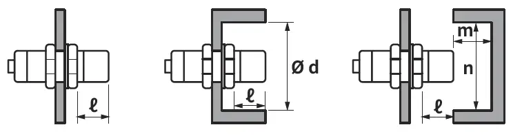
Influence by surrounding metals
When sensors are mounted on metallic panel, it must be prevented sensors from being affected by any metallic object except target. Therefore, be sure to provide a minimum distance as below chart
| Sensing side Item | Ø 8 mm | Ø 12 mm | Ø 18 mm | Ø 30 mm | ||||
| Flush | Non- flush | Flush | Non- flush | Flush | Non- flush | Flush | Non- flush | |
| A | 9 | 12 | 12 | 24 | 30 | 48 | 60 | 90 |
| B | 16 | 24 | 24 | 36 | 36 | 54 | 60 | 90 |
| ℓ | 0 | 8 | 0 | 11 | 0 | 14 | 0 | 15 |
| Ø d | 8 | 24 | 12 | 36 | 18 | 54 | 30 | 90 |
| m | 4.5 | 6 | 6 | 12 | 15 | 24 | 30 | 45 |
| n | 12 | 24 | 18 | 36 | 27 | 54 | 45 | 90 |
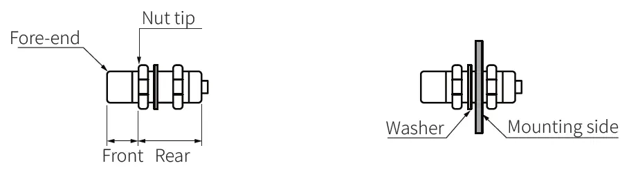
Tightening Torque
Use the provided washer to tighten the nuts. The tightening torque of the nut varies with the distance from the fore-end. [Figure 1] If the nut tip is located at the front of the product, apply the front tightening torque. the allowable tightening torque table is for inserting the washer as [Figure 2].
| Sensing side Strength | Ø 8 mm | Ø 12 mm | Ø 18 mm | Ø 30 mm | ||||
| Flush | Non- flush | Flush | Non- flush | Flush | Non- flush | Flush | Non- flush | |
| Front size | 7 mm | 5 mm | 13 mm | 7 mm | – | – | 26 mm | 12 mm |
| Front torque | 3.92 N m | 6.37 N m | 14.7 N m | 49 N m | ||||
| Rear torque | 8.82 N m | 11.76 N m | 14.7 N m | 78.4 N m | ||||
18, Bansong-ro 513Beon-gil, Haeundae-gu, Busan, Republic of Korea, 48002 www.autonics.com | +82-2-2048-1577 | [email protected]


 Rectangular Flat Type Inductive Proximity Sensors Instruction Manual")


