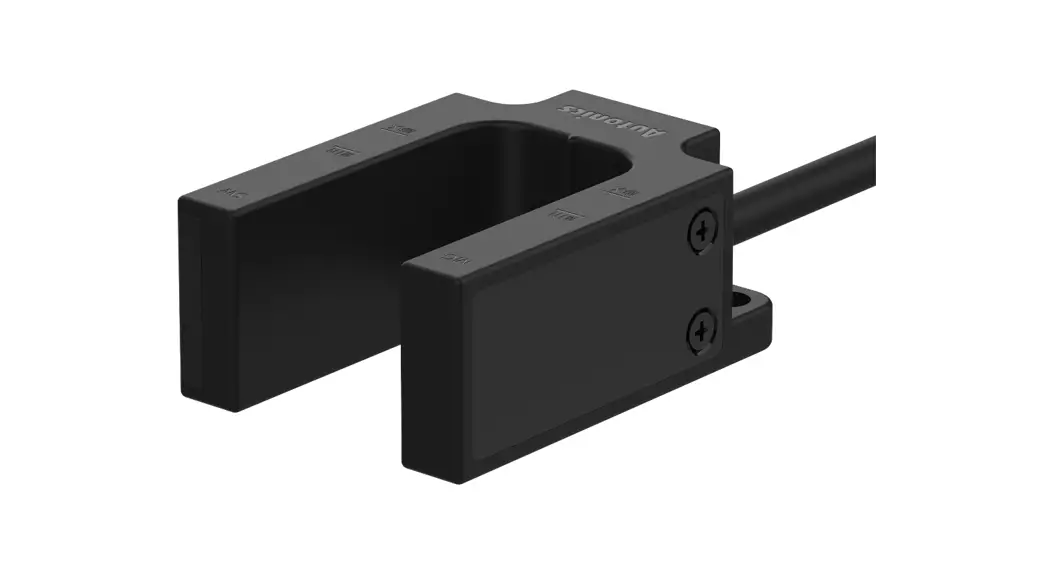
![]() U-shaped Magnetic Proximity Sensor
U-shaped Magnetic Proximity Sensor
MU Series
PRODUCT MANUAL
MU Series U-shaped Magnetic Proximity Sensor
For your safety, read and follow the considerations written in the instruction manual, other manuals and Autonics website.
The specifications, dimensions, etc. are subject to change without notice for product improvement. Some models may be discontinued without notice.
Features
- Non-voltage magnetic detection method
- Two wiring specifications of cable / cable connector type
- IP67 protection structure (IEC standard)
Safety Considerations
- Observe all ‘Safety Considerations’ for safe and proper operation to avoid hazards.
 symbol indicates caution due to special circumstances in which hazards may occur.
![]() Warning Failure to follow instructions may result in serious injury or death.
Warning Failure to follow instructions may result in serious injury or death.
- Fail-safe device must be installed when using the unit with machinery that may cause serious injury or substantial economic loss. (e.g. nuclear power control, medical equipment, ships, vehicles, railways, aircraft, combustion apparatus, safety equipment, crime/disaster prevention devices, etc.)
Failure to follow this instruction may result in personal injury, economic loss or fire. - Do not use the unit in the place where flammable/explosive/corrosive gas, high humidity, direct sunlight, radiant heat, vibration, impact, or salinity may be present.
Failure to follow this instruction may result in explosion or fire. - Do not disassemble or modify the unit.
Failure to follow this instruction may result in fire. - Do not connect, repair, or inspect the unit while the load is connected to a power source.
Failure to follow this instruction may result in fire. - Check ‘Connections’ before wiring.
Failure to follow this instruction may result in fire.
![]() Caution Failure to follow instructions may result in injury or product damage.
Caution Failure to follow instructions may result in injury or product damage.
- Use the unit within the rated specifications.
Failure to follow this instruction may result in fire or product damage. - Use a dry cloth to clean the unit, and do not use water or organic solvent.
Failure to follow this instruction may result in fire. - Make cable length as short as possible.
Failure to follow this instruction may result in malfunction. - Do not install the switch on the magnetic object or in the environment of ferromagnetic fields. Use bolt and nut of stainless steel or nonmagnetic material, when installing the switch.
Failure to follow this instruction may result in malfunction or affect sensing distance. - Do not use a load over the range of rated relay specification.
Failure to follow this instruction may result in fire, relay broken, contact melt, insulation failure or contact failure.
Cautions during Use
- Follow instructions in ‘Cautions during Use’. Otherwise, it may cause unexpected accidents.
- If excessive shock or vibration is applied to the product, it may cause bounce or malfunction.
- Use the slow mode filter to avoid bounce and chattering. Bounce and chattering may occur when high-speed mode (≤ 1 ms) filter is applied.
- This unit may be used in the following environments.
– Indoors (in the environment condition rated in ‘Specifications’)
– Altitude max. 2,000 m
– Pollution degree 3
– Installation Category Ⅱ
Product Components
- Product
- Instruction manual
Ordering Information
This is only for reference, the actual product does not support all combinations.
For selecting the specified model, follow the Autonics website.
MU – ① – 30 – ②
❶ Contact type
1A: Normally open
1B: Normally closed
❷ Cable type
No mark: cable type (2 m)
E: Cable connector type (0.5 m)
Specifications
| Model | MU-1A-30-□ | MU-1B-30-□ | |
| Contact | N.O. | N.C. | |
| Operating distance 01) | OFF → ON | ± 10 mm | |
| ON → OFF | ± 20 mm | ||
| Standard sensing target | Steel plate – a galvanized steel sheet 1.6t | ||
| Operating time | ≤ 2 ms | ||
| Release time | ≤ 1 ms | ||
| Operating frequency | ≤ 500 Hz | ||
| Approval | |||
| Unit weight (package) | Cable type: ≈ 132.5 g (≈ 172.3 g) Cable connector type: ≈ 107 g (≈ 147.2 g) | ||
01) Rated at the ambient temperature of 23 ℃. It can be differed up to ±20 % according to the ambient temperature.
| Switching voltage | ≤ 24 VDC |
| Life expectancy | ≥ 100 million times (at a resistive load of 5 VDC |
| Insulated resistance | ≥ 1,000 MΩ (500 VDC |
| Dielectric strength | 500 VAC∼ 50/60 Hz for 1 minute (between all terminals and case) |
| Vibration | 1.5 mm double amplitude at frequency of 10 to 55 Hz (for 1 minute) in each X, Y, Z direction for 2 hours |
| Shock | 100 m/s² (≈ 10 G) in each X, Y, Z direction for 3 times |
| Ambient temperature | -10 to 65 °C, storage: -10 to 70 °C (no freezing or condensation) |
| Ambient humidity | 35 to 85 %RH, storage : 35 to 85 %RH (no freezing or condensation) |
| Protection structure | IP67 (IEC standard) |
| Connection | Cable type / Cable connector type |
| Cable | Cable type: Ø 4, 2-wire, 2 m (UL Style 20276, AWG22) Cable connector type: Ø 4, 2-wire, 0.5 m (UL Style 20276, AWG22) |
| Material | Cover/Case: PC (915R) |
■ Applied REED SWITCH
| Model | ORD324-10-15 (STANDEX MEDER) |
| Contact | A (SPST-NO: single pole, single throw, normally open) |
| Contact rating 01) | ≤ 10 W/VA |
| Voltage | Switching: ≤ 200 VDC |
| Current | Switching: ≤ 0.5 A, Carry: ≤ 1.0 A |
| Ambient temperature | -40 to 125 ℃, storage : -65 to 125 ℃ 02) |
| Material | Body: glass, leads: tin-plated Ni-Fe wire |
01) Switching voltage and current should never exceed the wattage rating.
02) Long time exposure at elevated temperature may degrade solderability of the leads.
Operating Distance
- Operating distance is the distance between the center line of switch and the target.
- Install the product to be operated within the ± 20 % of the operating distance.
- The operating distance may be affected by metal or magnetic substances which is placed closely to the switch.
| Moving direction | Operating distance |
| Up → Down | 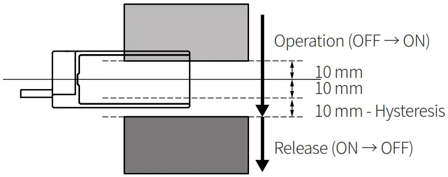 |
| Down → Up | 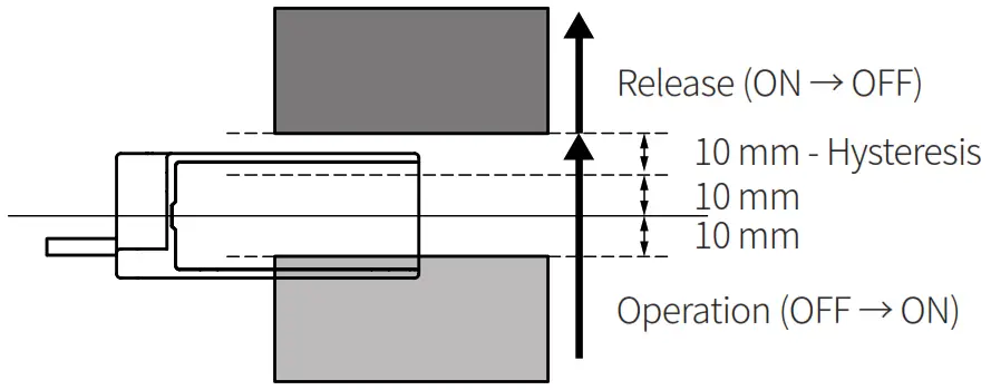 |
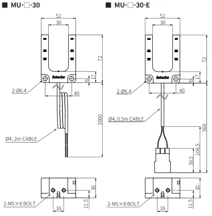
Dimensions
- Unit: mm, For the detailed dimensions of the product, follow the Autonics web site.
Connections
■ MU-1A-30-□
| Pin | Color | Function | Internal circuit |
| 4 | Blue | Normally Open |  |
| 5 | Brown |
■ MU-1B-30-□
| Pin | Color | Function | Internal circuit |
| 4 | Blue | Normally Closed |  |
| 5 | Brown |
- Pin arrangement
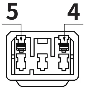
Connector: Daedong Inc., MIC-5M
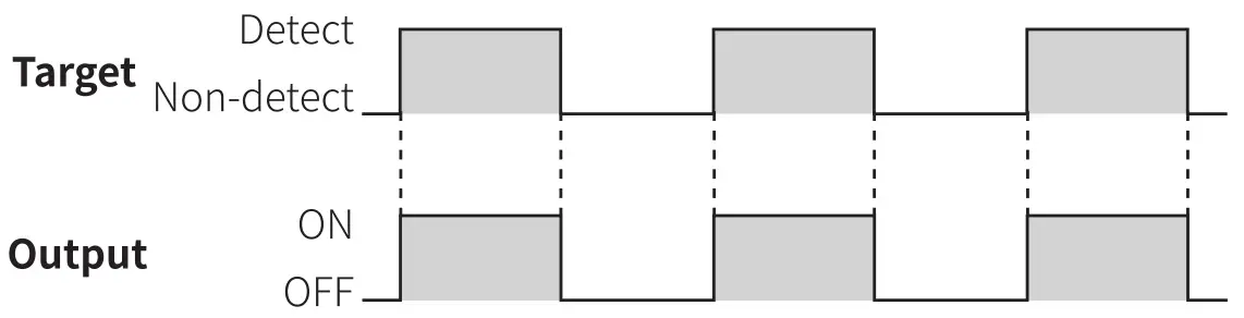
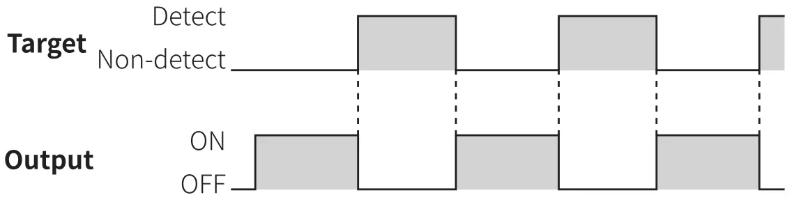
Timing Diagram
■ MU-1A-30-□
■ MU-1B-30-□
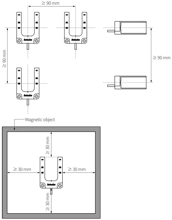
Cautions during Installation
- Install the product according to the rated specifications, environment, and place.
- Tighten the M5 screw with the tightening torque of 0.8 N.m.
- Installing more than 2 switches closely may result in malfunction due to mutual interference.
Keep the distance between units.
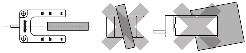
- Install the switch to the position where the center of the switch and the target be exactly horizontal and vertical.

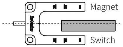
- If it is hard to align along the center line, install the switch to the position where the target is closer to the switch part, rather than magnet part.
Otherwise, the target can be attached to the magnet part, so that it can result in malfunction.
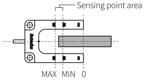
- Install the switch to the position where the target passes the sensing point area.
Sensing point area: area between 30 mm point and 40 mm point from the end of the switch
![]() 18, Bansong-ro 513Beon-gil, Haeundae-gu, Busan,
18, Bansong-ro 513Beon-gil, Haeundae-gu, Busan,
Republic of Korea, 48002
www.autonics.com
+82-2-2048-1577
[email protected]


 Cylindrical Inductive Proximity Sensors Instruction Manual")


 Rectangular Flat Type Inductive Proximity Sensors Instruction Manual")


