
Friendcom IDUV915-LRW Inductive Sensor Endpoint
About the Product
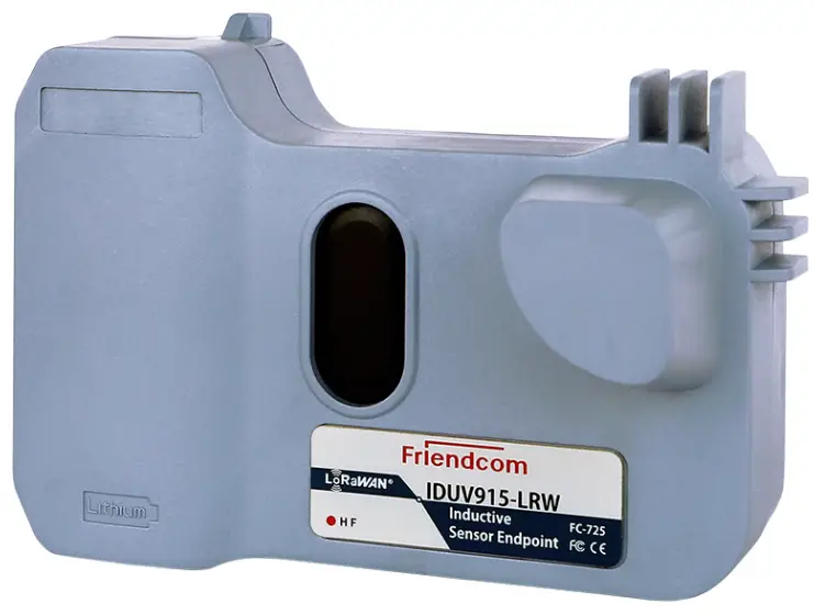
The IDUV915-LRW Inductive Sensor Endpoint is a model name FC-725 product manufactured by Friendcom CO., LTD. It is a LoRaWAN Terminal Series version 1.2 device used for detecting and measuring the presence of metallic objects using inductive sensing technology. The device is designed to be connected with customers’ applications.
Product Features
- Inductive sensing technology for detecting metallic objects
- LoRaWAN communication protocol for long-range wireless connectivity
- Low power consumption for extended battery life
- Compact and lightweight design for easy installation
Product Usage Instructions
The IDUV915-LRW Inductive Sensor Endpoint is intended for use by system engineers (SEs), application engineers, and test engineers. Before using the device, please refer to the following documents:
- Friendcom_IDUV915-LRW_Inductive_Sensor_Endpoint_Terminal_Datasheet
- Friendcom_IDUV915-LRW_Inductive_Sensor_Endpoint_Configuration_Guide
To use the device, follow the steps below:
- Install the device according to the instructions provided in the configuration guide.
- Connect the device to your application using the appropriate communication protocol.
- Power on the device and wait for it to establish a connection with your application.
- The device will detect the presence of metallic objects and
send data to your application using the LoRaWAN protocol.
If you encounter any issues or require technical support, please contact Friendcom Technology Co., Ltd. using the contact information provided in the user manual.
Friendcom has always been committed to technological innovation. Our aim is to provide customers with timely and comprehensive service. For any assistance, please contact our Shenzhen headquarters:
FRIENDCOM TECHNOLOGY CO., LTD.
7th Floor, 17 Building, Guangqian Industrial Park, Xili Town, Nanshan District, Shenzhen, 518055, China
- Tel: +86-755-86026600
- +86-755- 23230320
- Fax: +86-755-86026300
For technical support, or to report documentation errors, please visit:
http://www.friendcom.com Or email to: [email protected]
NOTICE
Information in this document has been carefully reviewed and is considered to be accurate. However, Friendcom assumes no liability resulting from any inaccuracies or omissions in this document, or from use of the information obtained herein. Friendcom reserves the right to make changes to any products described herein and reserves the right to revise this document and to make changes from time to time in content hereof with no obligation to notify any person of revisions or changes. Friendcom does not assume any liability arising out of the application or use of any product described herein.
COPYRIGHTS
This manual and Friendcom products described herein may include or describe copyrighted Friendcom material and are considered technical proprietary of Friendcom CO., LTD. Accordingly, any copyrighted material of Friendcom and its licensors contained herein or in Friendcom products described in this manual may not be copied, reproduced, distributed, merged or modified in any manner without the express written permission of Friendcom.
TRADEMARKS
and Friendcom logo are registered Trademarks. All other product or service names which are mentioned in this document are the property of their respective owners.
About This Document
Scope
Scope of this document is to present features and application of Friendcom IDUV915-LRW Inductive Sensor Endpoint(Model name FC-725).
Audience
This document is intended for system engineers (SEs), application engineers, and test engineers.
Related Documents
- Friendcom_IDUV915-LRW_Inductive_Sensor_Endpoint_Terminal_Datasheet
- Friendcom_IDUV915-LRW_Inductive_Sensor_Endpoint_Configuration_Guide
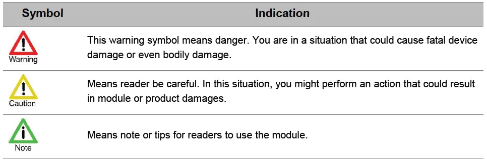
Conventions
History
| 1.0 | 2021-01 | Initial draft |
| 1.1 | 2021-03 | Modify the power consumption |
| 1.2 | 2021-04 | Modify the product name |
Introduction
This document describes the technical parameters and key functions which are connected with customers’ applications, and it can help customers quickly understand the data format, features, as well as other related information of IDUV915-LRW Inductive Sensor Endpoint.
Product Concept
General Description
IDUV915-LRW Inductive Sensor Endpoint is a data acquisition and transmission terminal, which is widely used in the intelligent construction of water meters, gas meters, and heat meters. It can realize data collection, data storage management, abnormal warning and wireless communication functions. IDUV915-LRW based on a high performance LoRaWAN module, it supports standard wireless LoRaWAN protocol. IDUV915-LRW built-in high-performance non-magnetic metering module, can detect rotating metal target in meters to measure the volume of flow. It is completely diamagnetic and has strong anti-interference. With pre-installed long-life battery and built-in antenna, the IDUV915-LRW has the characteristics of simple deployment, high reliability, low power consumption and long transmission distance.
Key Features
The following shows the key features of IDUV915-LRW.
- Immunity of magnet interference.
- Supports a range of event alarms including:battery life, reverse flow, Disassemble etc.
- Waterproof: IP67.
- Suitable to workin harsh environment.
- Long range wireless data transmission.
- Multi-band support, EU433, CN470, EU868, US915, AU915, IN865, etc.
- Pre-installed long-life battery and built-in antenna.
- Air wireless configuration.
- Firmware upgrade by FOTA.
- Average life 10 years*.
NOTE
Lifetime depends from the device location and reporting interval.
Curve freezing function introduction
The IDUV915-LRW also supports more flexible data collection point configuration. Compared to the traditional recording method, the curve freezing function can help users record the usage of each time period of the day and report the data. In order to meet this demand, the IDUV915-LRW program will average 96 time points in a day, and the interval between time points It is 15 minutes, as shown in the table below
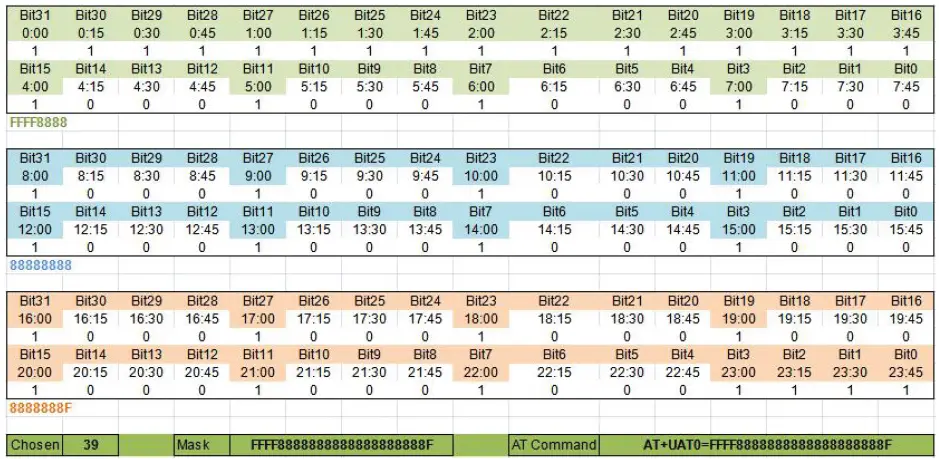 Curve reporting function has two reporting frame format, one is the default curve reporting frame, its acquisition point settings such as Table 2-1. ( 4 am to 11 pm every 1hour. 11 pm to 4 am every 15 minutes) The other is the user-defined curve reporting frame. The user can set any desired data collection plan by modifying the 12-byte mask. The mask corresponding to the above figure is FFFF8888888888888888888F. The mask can be obtained through the separately provided data collection schedule.
NOTE
Due to the limitation of the data length of the reported frame, a maximum of 77 data collection points are currently supported. If the collection point set by the user exceeds 77, the mask and AT command will not be displayed.
Specifications
The following table describes the specifications of IDUV915-LRW
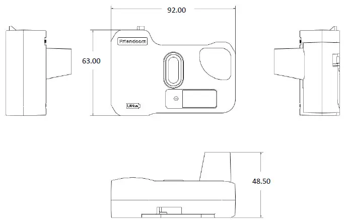
| Dimension | 92mm (L) x 63mm(W) x 48.5 mm (H) |
| Weight | 70g (The weight of packing material is not included) |
| Battery Life | Average life 10 years |
| Communication range | Up to 15km (In visibility conditions) |
| Radio Characteristics | Tx Power: Max. 20dBm Rx Sensitivity: < -138dBm |
| Power Consumption | Average 8.5uA @ absence of water flow Average 11.5uA @ presence of water flow |
| MAC Layer | LoRaWAN ® |
| IP Rating | IP67 |
| Working Bands | EU433, CN470, EU868, US915, AU915, IN865, etc. |
| Operating Temperature | -40°C to +70°C (Industrial Grade) |
| Operating humidity | 5%RH to 95%RH |
| Antenna Option | Build-in Antenna |
| Power Supply | Pre-installed long-life battery, 2.6V to 3.7V |
| Configuration | Over-the-air |
| Upgrade | FOTA |
| Environmental Compliance | RoHS, REACH |
| Certification | CE, FCC, LoRa Alliance* |
Means for features and certifications in planning
Safety Recommendations
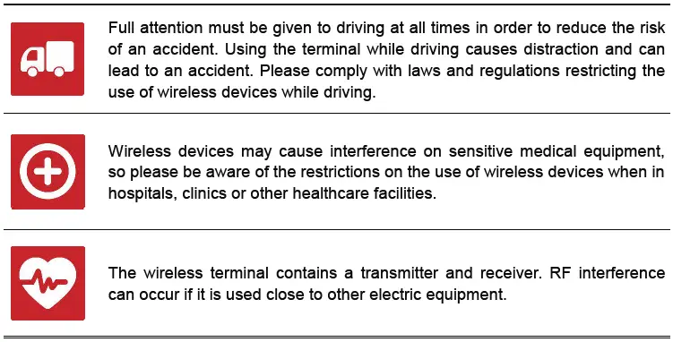
Ensure that this product is used in compliant with the requirements of the country and the environment, the following safety precautions must be observed during all phases of the operation, such as usage, service or repair of wireless pulse acquisition products. If not so, Friendcom assumes no liability for customers’ failure to comply with these precautions

Data Format and Setting Command
Data Format of Reporting
IDUV915-LRW actively reports data according to the set period. The format of reported data frame can be set to four types: short format, long format, default curve and custom curve. The information reported in the four formats is different, as follows: Short data frame format:
| Name | Byte | Note |
| Frame header | 1 | Fixed 0x56 |
|
Frame number and status |
1 | Bit 4- Bit 7: Frame number Bit 3: Downlink command successful reply mark,0 means no reply, 1 means the last command issued by the server was successfully executed. Bit 2: Open the lid detection mark, 0 means the shell is normal, 1 means the shell is abnormal.This bit is cleared after the cover is re-closed. Bit 1: Reverse flow identification, 0 means no reverse flow, 1 means there is reverse flow.This bit is cleared after any report is successful. Bit 0: Low voltage alarm flag, 0 means normal, 1 means abnormal |
| Reverse pulse number | 4 | BCD code, unit L, current reverse cumulative count. |
| Data area | 4 | BCD code,Unit L, current cumulative number |
| Checksum | 1 | Accumulate sum, the cumulative sum of one byte of data from the frame header to the check |
Long data frame format
| Name | Byte | Note |
| Frame header | 1 | Fixed 0x55 |
| Frame number | 1 | Data frame accumulator, value range 0 to 255, cyclic accumulation |
| Address field | 4 | BCD code, unit L, current reverse cumulative count. |
| Function code | 1 | Fixed 0x01 |
| Data area | 4 | BCD code, unit L, current cumulative number |
| Freeze data on previous day | 4 | BCD code, unit L |
| Clock | 6 | Format is Year, month, day, hour, minute |
| Battery voltage | 1 | Current battery voltage, the actual voltage value needs to be divided by 10 |
|
Status byte |
1 | Bit 4-Bit 7: Reserved. Bit 3: Downlink command successful reply mark,0 means no reply, 1 means the last command issued by the server was successfully executed. Bit 2: Open the lid detection mark, 0 means the shell is normal, 1 means the shell is abnormal.This bit is cleared after the cover is re-closed. Bit 1: Reverse flow identification, 0 means no reverse flow, 1 means there is reverse flow.This bit is cleared after any report is successful. Bit 0: Low voltage alarm flag, 0 means normal, 1 means abnormal |
| Checksum | 1 | Accumulate sum, the cumulative sum of one byte of data from the frame header to the check |
| Terminator | 1 | Fixed 0x16 |
Default curve frame format
| Default curve report frame | |||
| Data field | Field length | Example | Example data description |
| Start fixed at 0x57 | 1 | 0x57 | Fixed HEX0x57 |
| Timestamp | 3 | 0x210303 | March 03, 2021 (BCD code) |
| 0:00 Freeze data | 3 | 0x003039 | 0:00 frozen to 12345.6 cubic meters (HEX) |
| 0:15 | 1 | 0x01 | 0:00-0:15 increased by 0.1 cubic(HEX) |
| 0:30 | 1 | 0x02 | 0:15-0:30 increased by 0.2 cubic (HEX) |
| 0:45 | 1 | 0x03 | 0:30-0:45 increased by 0.3 cubic(HEX) |
| 1:00 | 1 | 0x04 | 0:45-1:00 increased by 0.4 cubic(HEX) |
| 1:15 | 1 | 0x05 | – |
| 1:30 | 1 | 0x06 | – |
| 1:45 | 1 | 0x07 | – |
| 2:00 | 1 | 0x08 | – |
| 2:15 | 1 | 0x09 | – |
| 2:30 | 1 | 0x0A | – |
| 2:45 | 1 | 0x0B | – |
| 3:00 | 1 | 0x0C | – |
| 3:15 | 1 | 0x0D | – |
| 3:30 | 1 | 0x0E | – |
| 3:45 | 1 | 0x0F | – |
| 4:00 | 1 | 0x10 | 3:45-4:00 increased by 1.6 cubic(HEX) |
| 5:00 | 1 | 0x11 | 4:00-5:00 increased by 1.7 cubic(HEX) |
| 6:00 | 1 | 0x12 | – |
| 7:00 | 1 | 0x13 | – |
| 8:00 | 1 | 0x14 | – |
| 9:00 | 1 | 0x15 | – |
| 10:00 | 1 | 0x16 | – |
| 11:00 | 1 | 0x17 | – |
| 12:00 | 1 | 0x18 | – |
| 13:00 | 1 | 0x19 | – |
| 14:00 | 1 | 0x1A | – |
| 15:00 | 1 | 0x1B | |
| 16:00 | 1 | 0x1C | – |
| 17:00 | 1 | 0x1D | – |
| 18:00 | 1 | 0x1E | – |
| 19:00 | 1 | 0x1F | – |
| 20:00 | 1 | 0x01 | – |
| 21:00 | 1 | 0x02 | – |
| 22:00 | 1 | 0x03 | – |
| 23:00 | 1 | 0x04 | 22:00-23:00 increased by 0.4 cubic(HEX) |
| 23:15 | 1 | 0x05 | 23:00-23:15 increased by 0.5 cubic(HEX) |
| 23:30 | 1 | 0x06 | – |
| 23:45 | 1 | 0x07 | – |
| Status byte | 1 | 0x02 | The definition is the same as short frame status byte |
| Checksum plus mask CRC8 sum | 1 | 0xB4 | Checksum 0xF5+mask CRC8 0xBF |
| Terminator | 1 | 0x16 | Fixed HEX0x16 |
Custom curve frame format::
| Custom curve report frame | ||
| Data field | Field length | Example |
| Start fixed at 0x57 | 1 | 0x58 |
| Timestamp | 3 | 210304 |
| 0:00 Freeze data | 3 | 123456 |
| customize | 1 | 0x01 |
| customize | 1 | 0x02 |
| customize | 1 | 0x03 |
| customize | 1 | 0x04 |
| customize | 1 | 0x05 |
| customize | 1 | 0x06 |
| customize | 1 | 0x07 |
| customize | 1 | 0x08 |
| customize | 1 | 0x09 |
| customize | 1 | 0x0A |
| customize | 1 | 0x0B |
| customize | 1 | 0x0C |
| customize | 1 | 0x0D |
| customize | 1 | 0x0E |
| customize | 1 | 0x0F |
| customize | 1 | 0x10 |
| customize | 1 | 0x11 |
| customize | 1 | 0x12 |
| customize | 1 | 0x13 |
| customize | 1 | 0x14 |
| customize | 1 | 0x15 |
| customize | 1 | 0x16 |
| customize | 1 | 0x17 |
| customize | 1 | 0x18 |
| customize | 1 | 0x19 |
| customize | 1 | 0x1A |
| customize | 1 | 0x1B |
| customize | 1 | 0x1C |
| customize | 1 | 0x1D |
| customize | 1 | 0x1E |
| customize | 1 | 0x1F |
| customize | 1 | 0x01 |
| customize | 1 | 0x02 |
| customize | 1 | 0x03 |
| customize | 1 | 0x04 |
| customize | 1 | 0x05 |
| customize | 1 | 0x06 |
| customize | 1 | 0x07 |
| Status byte | 1 | 0x02 |
| Checksum plus mask CRC8 sum | 1 | 0xF7+mask CRC8 |
| Terminator | 1 | 0x16 |
Setting Command
Parameters of IDUV915-LRW can be set and read by AT command, the format of commands is shown in the following table
| Command | Note | Ack (Success) | Ack (Failure) |
| AT+JOINMODE=0 | Set OTAA mode | OK | Error |
| AT+APPEUI=xxxxxxxxxxxxx xxxxxxx | Set APPEUI e.g. AT+APPEUI=1122334455667788 | OK | Error |
| AT+APPKEY=xxxxxxxxxxxxx xxxxxxxxxxxxxxxxxxx | Set APPKEY e.g. AT+APPKEY=1122334455667788990011223 3445566 |
OK |
Error |
| AT+JOINMODE=1 | Set ABP mode | OK | Error |
| AT+NWKSKEY=xxxxxxxxxxx xxxxxxxxxxxxxxxxxxxxx | Set NWKSKEY e.g. AT+NWKSKEY=11223344556677889900112 233445566 |
OK |
Error |
| AT+APPSKEY=xxxxxxxxxxx xxxxxxxxxxxxxxxxxxxxx | Set APPSKEY e.g. AT+APPSKEY=11223344556677889900112 233445566 |
OK |
Error |
|
AT+URAM=F300,04 | Read the current number of pulses e.g.
[<- 11:07:16.259] AT+URAM=F300,04
[-> 11:07:16.324] +URAM:F300,04,12345678 Indicates that the current pulse is 0x78563412, that is, the low byte is before the high byte is after |
+URAM:F300,04 ,12345678 |
Error |
|
AT+URAM=F300,04,393000 00 | Write current pulse number Current number of pulses = current meter reading * pulse constant (the result retains the integer part) e.g. The current meter reading is 123.456 cubic meters and the pulse constant is 100, so the number of pulses should be 12345. The writing is also in accordance with the low byte first and the high byte after, for example, write 12345, 12345 = 0x00003039; [<- 11:12:08.076] |
OK |
Error |
| AT+URAM=F300,04,39300000 [-> 11:12:08.135] OK | |||
|
AT+URAM=F304,04 | Read the reporting period e.g.
[<- 11:13:33.539] AT+URAM=F304,04
[-> 11:13:33.604] +URAM:F304,04,A0050000 Indicates that the reporting period is 0x000005A0, that is, the low byte is before the high byte, and the reporting period is in minutes. |
+URAM:F304,04 ,A0050000 |
Error |
| AT+URAM=F304,04,a00500 00 | Write reporting period | OK | Error |
|
AT+URAM=F308,02 | Read pulse constant e.g.
[<- 11:16:50.579] AT+URAM=F308,02
[-> 11:16:50.644] +URAM:F308,02,0A00 Indicates that the current pulse is 0x000A, that is, the low byte is before the high byte, The pulse constant represents the number of pulses equal to 1 cubic meter, and the range is 1-2000 |
+URAM:F308,02 ,0A00 |
Error |
| AT+URAM=F308,02,0a00 | Write pulse constant | OK | Error |
|
AT+URAM=F30E,04 | Read device address e.g.
[<- 11:19:40.364] AT+URAM=F30E,04
[-> 11:19:40.425] +URAM:F30E,04,12345678 Indicates that the current device address is 0x12 0x34 0x56 0x78 |
+URAM:F30E,04 ,12345678 |
Error |
| AT+URAM=F30E,04,123456 78 | Write device address | OK | Error |
|
AT+URAM=F30A,01 | Read power output e.g.
[<- 11:24:38.124] AT+URAM=F30A,01
[-> 11:24:38.185] +URAM:F30A,01,00 00 means currently closed 01 means currently open |
+URAM:F30A,01 ,00 |
Error |
| AT+URAM=F30A,01,00 | Write power output off | OK | Error |
| AT+URAM=F30A,01,01 | Write power output on | OK | Error |
|
AT+URAM=F30B,01 | Read up and down configuration e.g.
[<- 11:24:38.124] AT+URAM=F30B,01
[-> 11:24:38.185] +URAM:F30B,01,00 00 means currently closed 01 means currently open |
+URAM:F30B,01 ,00 |
Error |
| AT+URAM=F30B,01,00 | Write up and down configuration Close | OK | Error |
| AT+URAM=F30B,01,01 | Write up and down configuration open | OK | Error |
|
AT+URAM=F30C,01 | Read measurement mode e.g.
[<- 11:24:38.124] AT+URAM=F30C,01
[-> 11:24:38.185] +URAM:F30B,01,00 00 means single pulse mode 01 means double pulse mode |
+URAM:F30B,01 ,00 |
Error |
| AT+URAM=F30C,01,00 | Write measurement mode Set single pulse | OK | Error |
| AT+URAM=F30C,01,01 | Write measurement mode Set double pulse | OK | Error |
|
AT+URAM=F30D,01 | Read frame format e.g.
[<- 11:24:38.124] AT+URAM=F30D,01
[-> 11:24:38.185] +URAM:F30D,01,00 00 means short frame format 01 means long frame format Note: If the transmission fails, the module will use the short frame format for a retransmission; |
+URAM:F30D,01 ,00 |
Error |
| AT+URAM=F30D,01,00 | Write frame format: Set short frame mode | OK | Error |
| AT+URAM=F30D,01,01 | Write frame format: Set long frame mode | OK | Error |
| AT+URAM=F30D,01,02 | Write frame format: Set default curve reporting mode | OK | Error |
| AT+URAM=F30D,01,03 | Write frame format: Set Custom Curve Reporting mode | OK | Error |
|
AT+SAVE | Save and apply parameters; Save RF parameters; Save the table parameters, and use the current time as the starting time of the reporting period. |
OK |
Error |
|
AT+UAT0? | This command can be used to query the data collection plan mask. e.g. [<- 15:26:42.991] AT+UAT0? [-> 15:26:43.059] |
will return the current mask |
Error |
| +UAT0:39,BF,FFFF8888888888888888888F Among them, 39 indicates that 39 collection points have been selected, and BF indicates that the CRC8 of the mask is 0xBF, and this value participates in the calculation of the check field of the curve report frame. | |||
| This command can be used to set the data | |||
| collection plan mask. | |||
| AT+UAT0=[12-byte mask] | e.g. [<- 15:40:29.965] | OK | Error |
| AT+UAT0=FFFF888888888888F888888F | |||
| [-> 15:40:30.028] OK | |||
| his command can be used to query the frozen | |||
| area data. | |||
| e.g. 1 | |||
| [<- 15:49:22.452] AT+UAT1? | |||
| [-> 15:49:22.507] +UAT1: No data available | |||
| If no data is returned, it means that there is no | |||
| data to be reported. | |||
| e.g. 2 | Return the latest | ||
| AT+UAT1? | [<- 15:56:18.812] AT+UAT1? [-> 15:56:18.956] | data to be reported in the | Error |
| +UAT1:00,Not,012103170004D20000C00000 | frozen area | ||
| C00000C00000C00000C00000C00000C000 | |||
| 00C00000C00000C00000C000000000002A8 | |||
| DD9 | |||
| 00: Indicates that the data is in block number | |||
| 00 | |||
| Not: indicates that the data is in a state to be | |||
| reported |
| Setting command:AT+UAT1=[block area | |||
| code], block area code 00-0F | |||
| e.g. 1 | |||
| [<- 16:18:46.649] AT+UAT1=00 | |||
| [-> 16:18:46.795] | |||
| +UAT1:00,OK,002103170004D20000C00000 | |||
| C00000C00000C00000C00000C00000C000 | |||
| 00C00000C00000C00000C000000000002A8 | |||
| D03 | |||
| 00: Indicates that the data is in block number | |||
| 00 | |||
| OK: indicates that the data has been | |||
| AT+UAT1=[block area code] | successfully reported
The format of the frozen area data is as | Return frozen area data | Error |
| follows: | |||
| ·Status: 1 byte, 00 means reported, 01 means | |||
| to be reported | |||
| ·Date BCD code: 3 bytes, such as 20 21 03 15 | |||
| ·Acquisition point 0 data: 3 bytes, the | |||
| definition is the same as the custom curve | |||
| report frame | |||
| ·Acquisition point 1-N data: 1 byte, coding | |||
| rules are the same as custom curve reporting | |||
| frame | |||
| ·Collection points: 1 byte, which is N | |||
| This command can be used to query the | |||
| reporting time | |||
| e.g. 1 | |||
| [<- 16:22:41.418] AT+UAT2? | |||
| [-> 16:22:41.495] +UAT2: Alarm 3 17:00:00, | |||
| Upload 08:15:00 + 11min | return the current | ||
| AT+UAT2? | 3 17:00:00: Indicates that the alarm timer | alarm time and | Error |
| value is 17:00:00 on the 3rd of the week | reported time | ||
| 08:15:00: Indicates that the reporting time is | |||
| 08:15:00 every day | |||
| + 11min: indicates that the random delay in | |||
| reporting is 11 minutes | |||
|
AT+UAT2=hh:mm | This command can be used to set the reporting time e.g. 1 [<- 16:45:53.584] AT+UAT2=09:15 |
OK |
Error |
| [-> 16:45:53.624] OK | |||
| Query current time | |||
| e.g. 1 | |||
| AT+RTC? | [<- 17:48:44.455] AT+RTC? [-> 17:48:44.511] +RTC:2021-03-17 | OK | Error |
| 17:48:44OK |
Parameters Configuration
Parameters Configuration
Before using the IDUV915-LRW, we need to configure some parameters, such as initial index, RTC real-time clock, upload frame type, AppKEY and other LoRaWAN information. For detailed operation steps, users can refer to Friendcom IDUV915-LRW Configuration Guide Manual.
Wireless Configuration Mode
Plug the wireless USB adapter FC-714-USB into your computer and install the correct driver to configure the product wirelessly.
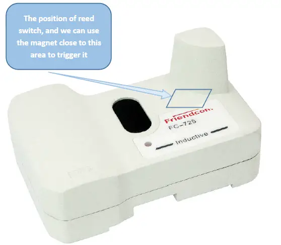
Entering Configuration Mode
IDUV915-LRW terminal can be activated by magnet to enter configuration mode. The reed switch inside the product is triggered by the magnet to put the product into the configuration mode, and then the configuration command must be sent within 30 seconds. If the product does not detect the configuration command in 30 seconds, the configuration mode will be exited. Once the command is received, the product will keep in configuration mode for another 30 seconds. The trigger position is shown in the figure below.
The time that magnet triggers the reed switch to connect (the duration from connect to the break) and the corresponding functions are shown in the following table:
| Magnet hold time | Features | Remarks |
| 2s-4s | Report data once | Typically 3s |
| 4s-9s | Configuration mode | Typically 5s |
| 9s-15s | Reset | Typically 12s |
| >15s | No response | Close magnet detecting function 60s |
- When the product exits the configuration mode, basing on whether the user has sent a network access command (AT + JOIN) and whether the current mode is OTAA, it will automatically join the network if both are satisfied. The network access result can be verified by triggering whether the data report is successful.
- The parameters can be set through AT command, for detailed command information, please refer to section 3.2.
Dimensions and Installation Instructions
Dimensions
The dimensions of IDUV915-LRW is show blew (unit mm).
Installation
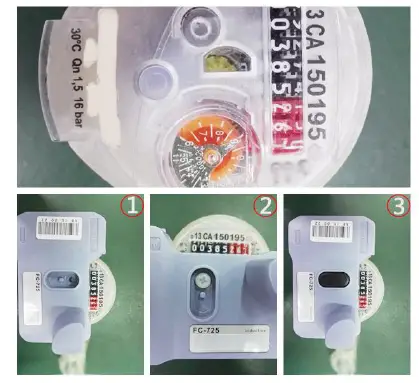
IDUV915-LRW use clasp and screw installation, Installation method:
- The module is fixed on the water meter with clasp
- Strengthened with screw.
- Put on the anti-disassembly plug.
Transportantion and Storage
Storage: -5C to 55C, non-corrosive gases.
Less than 4 layers stacked and pay attention to shockproof during transportation.
FCC Statement
This device complies with Part 15 of the FCC Rules. Operation is subject to the following two conditions:
- This device may not cause harmful interference.
- This device must accept any interference received, including interference that may cause undesired operation.
Changes or modifications not expressly approved by the party responsible for compliance could void the user’s authority to operate the equipment.
NOTE:
This equipment has been tested and found to comply with the limits for a Class B digital device, pursuant to Part 15 of the FCC Rules. These limits are designed to provide reasonable protection against harmful interference in a residential installation. This equipment generates uses and can radiate radio frequency energy and, if not installed and used in accordance with the instructions, may cause harmful interference to radio communications. However, there is no guarantee that interference will not occur in a particular installation. If this equipment does cause harmful interference to radio or television reception, which can be determined by turning the equipment off and on, the user is encouraged to try to correct the interference by one or more of the following measures:
- Reorient or relocate the receiving antenna.
- Increase the separation between the equipment and receiver.
- Connect the equipment into an outlet on a circuit different from that to which the receiver is connected.
- Consult the dealer or an experienced radio/TV technician for help.
To comply with RF exposure requirements, a minimum separation distance of 20cm must be maintained between the user’s body and the device.


