
![]()
Operating instructions
Solenoid interlock
AZM150
Version 2
About this document
Function
This operating instructions manual provides all the information you need for the mounting, set-up, and commissioning to ensure the safe operation and disassembly of the safety switchgear. The operating instructions must be available in a legible condition and a complete version in the vicinity of the device.
All operations described in this operating instructions manual must be carried out by trained specialist personnel, authorized by the plant operator only.
Please make sure that you have read and understood these operating instructions and that you know all applicable legislation regarding occupational safety and accident prevention prior to installation and putting the component into operation.
The machine builder must carefully select the harmonized standards to be complied with as well as other technical specifications for the selection, mounting, and integration of the components.
Explanation of the symbols used
 Information, hint, note:
This symbol indicates useful additional information.
 Caution: Failure to comply with this warning notice could lead to failures or malfunctions.
Warning: Failure to comply with this warning notice could lead to physical injury and/or damage to the machine.
Appropriate use
The products described in these operating instructions are developed to execute safety-related functions as part of an entire plant or machine. It is the responsibility of the manufacturer of a machine or plant to ensure the correct functionality of the entire machine or plant.
The safety switchgear must be exclusively used in accordance with the versions listed below or for the applications authorized by the manufacturer. Detailed information regarding the range of applications can be found in the chapter “Product description”.
General safety instructions
The user must observe the safety instructions in this operating instruction manual, the country-specific installation standards as well as all prevailing safety regulations and accident prevention rules.
Further technical information can be found in the Schmersal catalogs or in the online catalog on the Internet: products.schmersal.com.
The information contained in this operating instructions manual is provided without liability and is subject to technical modifications.
There are no residual risks, provided that the safety instructions, as well as the instructions regarding mounting, commissioning, operation, and maintenance, are observed.
Operating instructions Solenoid interlock
Warning about misuse
In case of improper use or manipulation of the safety switchgear, personal hazards or damages to machinery or plant components cannot be excluded. The relevant requirements of the standard EN ISO 14119 must be observed.
Exclusion of liability
We shall accept no liability for damages and malfunctions resulting from defective mounting or failure to comply with this operating instructions manual. The manufacturer shall accept no liability for damages resulting from the use of unauthorized spare parts or accessories. For safety reasons, invasive work on the device as well as arbitrary repairs, conversions, and modifications to the device are strictly forbidden, the manufacturer shall accept no liability for damages resulting from such invasive work, arbitrary repairs, conversions, and/or modifications to the device.
Product description
Ordering code
This operating instructions manual applies to the following types:
AZM150SK-➀R➁➂➃-➄-➅
| No. | Option | Description | |
| ➀ | 02 / 11 11 / 11 11 / 02 02 / 02 | Magnet: 2 NC 1 NO / 1 NC 1 NO / 1 NC 2 NC | 2 NCActuator: 1 NO / 1 NC 1 NO / 1 NC 2 NC 2 NC |
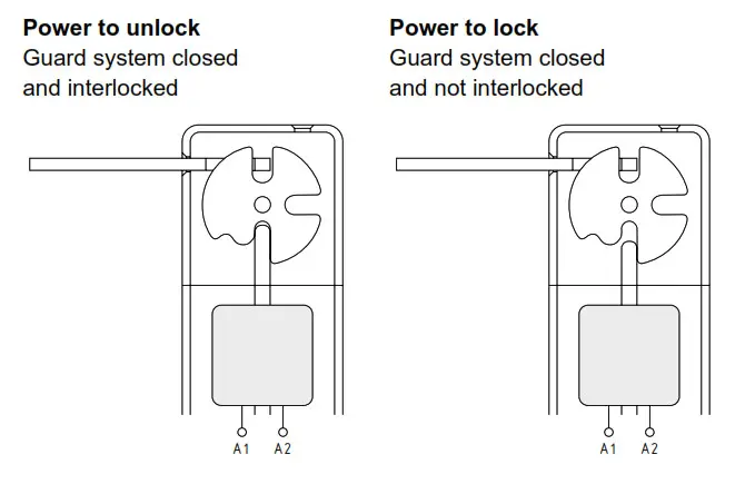
| ➁ ➂ ➃ ➄ ➅ | I A T N 024 110 230 B1 B5 B6L B6R | Standard coded (Actuator not included in delivery) Individually coded (incl. actuator, see ➅) Power to unlockPower to lock Manual release Emergency Exit Emergency release Us 24 VDC Us 110 VAC Us 230 VAC Including actuator for individually coded versions I: Straight actuator B1 included Angled actuator B5 included incl. flexible actuator B6, left incl. flexible actuator B6, right | |
| AZM150-B1 AZM150-B5 AZM150-B6 | Straight actuator Angled actuator Flexible actuator |
Standard coded actuator (not included in delivery)
Only if the information described in this operating instructions manual is realized correctly, the safety function and therefore the compliance with the Machinery Directive is maintained.
Special versions
For special versions, which are not listed in the order code below 2.1, these specifications apply accordingly, provided that they correspond to the standard version.
Purpose
The solenoid interlock has been designed to prevent in conjunction with the control part of a machine, movable safety guards from being opened before hazardous conditions have been eliminated. The AZM150 solenoid interlocks with individual coding offer higher protection against tampering and remain off when the guard system is unlocked or open.
Interlocks with the power to lock principle may only be used in special cases after a thorough evaluation of the accident risk since the safety guard can be opened immediately on the failure of the power supply or upon activation of the main switch.
The safety switchgear is classified according to EN ISO 14119 as type 2 interlocking devices. Designs with individual coding are classified as highly coded.
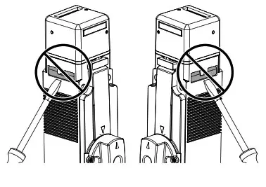
Manual release (for set-up, maintenance, etc.)
The rear and cover-side manual release can be actuated independently of one another. Check that both are in the starting position when putting the device into operation.
The manual release is realized by turning the triangular key so that the locking bolt is pulled into the unlocking position. The normal locking function is only restored after the triangular key has been returned to its original position. After being put into operation, the manual release must be secured by installing the seals, which are included in the delivery.
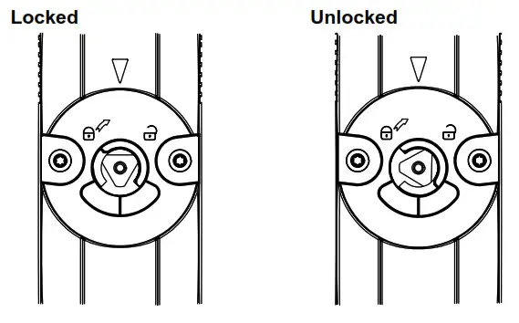
Triangular key TK-M5 (101100887) is available as an accessory.
Emergency release (ordering suffix -N)
(Fitting only from outside the hazardous area)
The emergency release should only be used in an emergency.
The solenoid interlock should be installed and/or protected so that an inadvertent opening of the interlock by an emergency release can be prevented.
The emergency release must be clearly labeled that it should only be used in an emergency. The label can be used that was included in the delivery.
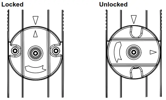
To activate the emergency release, turn the red lever 90 in the direction of the arrow as far as it will go. In this position, the safety guard can be opened. The lever is latched and cannot be returned to its original position. To cancel the blocking condition, the central mounting screw must be loosened to such an extent that the lever can be turned back into its original position. The screw must then be re-tightened.
Operating instructions Solenoid interlock
Emergency exit (Ordering suffix -T)
(Fitting and actuation only from within the hazardous area) To activate the emergency exit of version T, turn the red lever 90 in the direction of the arrow as far as it will go. In this position, the safety guard can be opened. The blocked position is canceled by turning the lever in the opposite direction. In an unlocked position, the safety guard is protected against unintentional closing.
Emergency release / Emergency exit
The user must evaluate and design the safety chain in accordance with the relevant standards and the required safety level.
The entire concept of the control system, in which the safety component is integrated, must be validated to the relevant standards.
| S+C36:D43tandards: | EN 60947-5-1, EN ISO 14119 |
| Enclosure: | glass-fibre reinforced thermoplastic, self-extinguishing |
| Actuator and locking bolt: | stainless steel 1.4301 |
| Contact material: | Silver |
| Coding level according to EN ISO 14119: – Standard coding version: – Individual coding version: | low high |
| Degree of protection: | |
| Insulation protection class: | II |
| Degree of protection: | IP65, IP67 |
| Insulation protection class: | II, |
| Overvoltage category: | II |
| Degree of pollution: | 2 |
| Contact type: | Change-over contact with double break type Zb, with galvanically separated contact bridges |
| Switching system: | B acc. EN 60947-5-1 slow action, NC contact with positive break |
| Positive break travel (unlocked): | 5 mm |
| Positive break force (unlocked): | 10 N for each NC contact fitted |
| Connection: | screw terminals |
| Cable type: | flexible |
| Max. cable section: | 0.25 mm² … 1.5 mm² (incl. conductor ferrules without plastic collar) |
| Cable entry: | 3x M20 |
| Holding force Fmax: | 1,950 N |
| Holding force FZh: | 1,500 N |
| Latching force: | 50 N |
| Actuating speed: | 0.3 m/s |
| Actuating frequency: | max. 1,000 operations/h |
| Mechanical life: | 1,000,000 operations |
| Ambient temperature: | -25 °C … +55 °C |
| Storage temperature: | –40 °C … +85 °C |
| Relative humidity: | max. 93 %, noncondensing, noticing |
| Electrical data: | |
| Electrical data: Utilization category: – Rated operating current/voltage Ie/Ue: | AC-15, DC-13 4 A / 230 VAC 4 A / 24 VDC |
| Rated impulse withstand voltage Uimp: | 4 kV |
| Rated insulation voltage Ui: | 300 V |
| Thermal test current Ithe: | 5 A |
| Max. fuse rating: | 6 A gG |
| Required rated short-circuit current: | 1,000 A |
| Rated control voltage Us: | 24 VDC 110 VAC 230 VAC |
| Electrical data – Magnet control: | |
| Magnet switch-on time: | 100% |
| Power consumption: | max. 8.5 W |
| Accepted test pulse duration on input signal: – With test pulse interval of: | ≤ 5.0 ms ≥ 50 ms |
Safety classification of the interlock function
| Standards: | EN ISO 13849-1 |
| Envisaged structure: – Basically: – With 2-channel usage and fault exclusion mechanism*: | applicable up to Cat. 1 / PL c applicable up to Cat. 3 / PL with a suitable logic unit |
| B10D NC contact: | 2,000,000 |
| B10D NO contact at 10% ohmic contact load: | 1,000,000 |
| Mission time: | 20 years |
MTTF D=B10D/0,1 x nop
nop=D op x hop x 3600s/h/t cycle
If the device is used as an interlock for personal safety, a safety classification of the guard locking function is required.
When classifying the interlock function, a distinction must be made between monitoring of the interlock function (locking function) and controlling the unlocking function.
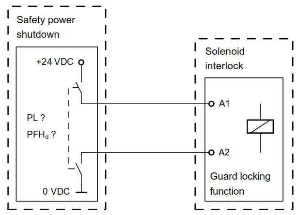
The following safety classification of the unlocking function is based on the application of the principle of safety energy disconnection for the solenoid supply.
The classification of the unlocking function is only valid for devices with monitored guard locking function and in the power to unlock version (see ordering code).
A fault exclusion for the guard locking function can be assumed by an external safety energy disconnection.
In this case, the guard locking function does not have an effect on the failure probability of the unlock function.
Operating instructions Solenoid interlock
The safety level of the unlock function is determined exclusively by the external safety power shutdown.
Fault exclusion with regard to wiring routing must be observed.If for a certain application the power to unlock version of a solenoid interlock cannot be used, for this exception an interlock with power to lock can be used if additional safety measures need to be realized that have an equivalent safety level.
Assembly
General mounting instructionsPlease observe the remarks of the standards
EN ISO 12100, EN ISO 14119 and EN ISO 14120.
4 M5 holes are provided for mounting the enclosure. The solenoid interlock is double insulated. The use of an earth wire is not authorized. The solenoid interlock must not be used as an end stop. Any mounting position. The mounting position however must be chosen so that the ingress of dirt and soiling in the used opening is avoided. Unused actuator openings must be sealed with slot sealing plugs.
Detailed information on actuators with standard coding (not included in delivery) AZM150-B1, AZM150-B5 and AZM150-B6 and their mounting can be found in the actuator operating instructions.
The insertion funnel on the head of the interlock allows insertion of a flexible actuator with an axial offset of ≤ ±1 and a height offset of ≤ ±1. The actuator must be inserted into the actuator head easily. For doors that do not ensure this is possible, a door catch must be installed to prevent damage to the device.When used in ambient temperatures > 40°C, the solenoid interlock must be protected against contact with inflammable materials or inadvertent personal contact.
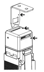
Choosing the actuating planes
Offsetting the actuating head enables actuation of 8 levels.
- Cover screws must be loosened
- Remove cover
- Turn to actuate head to the desired position
- Fit the cover and engage, tighten the cover screws (torque 0.5 Nm)
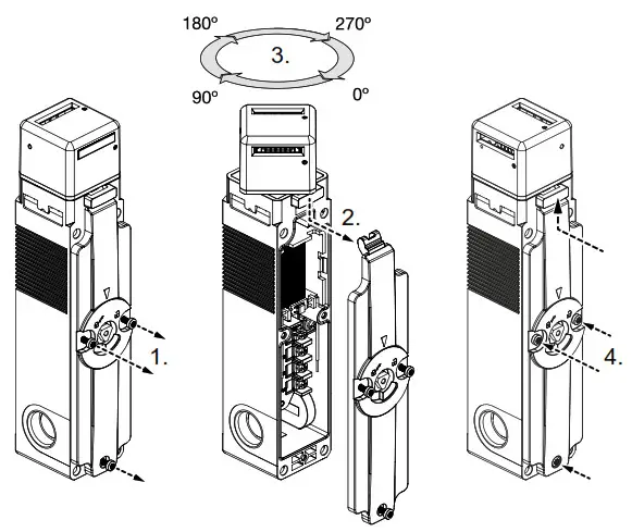
Do not lever out the side tabs. Levering out the tabs will damage the device.
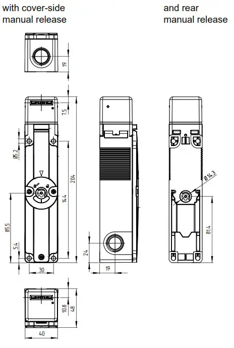
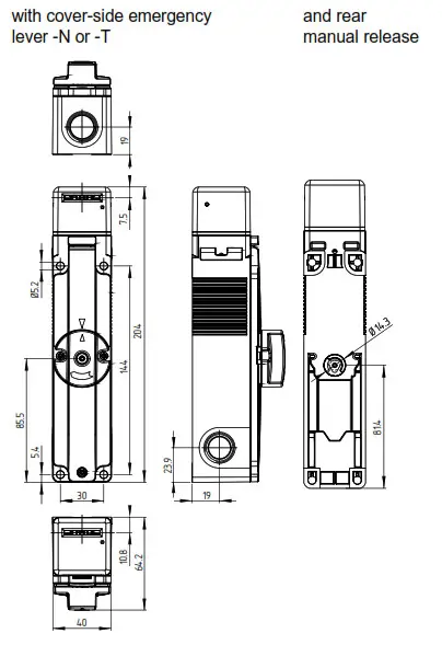
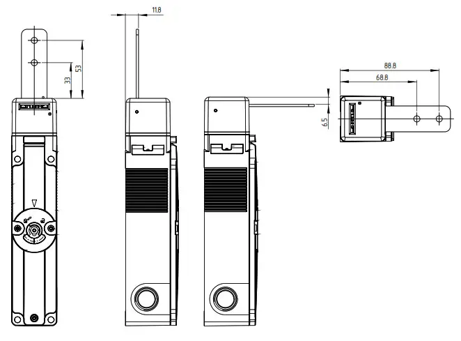
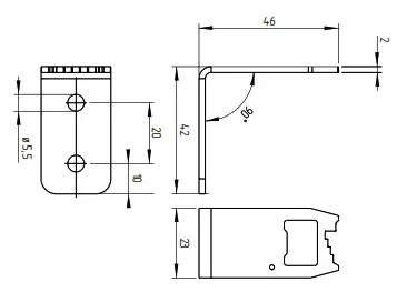
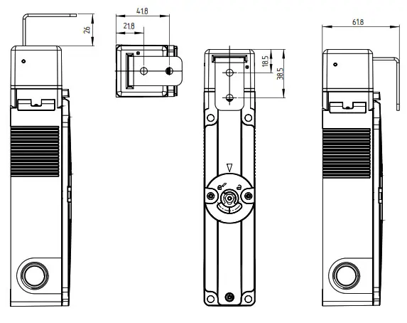
Dimensions
All measurements in mm.
AZM150
Operating instructions Solenoid interlock
AZM150
Mounting of individually coded actuatorsThe marks on the used actuator opening of the solenoid interlock and on the actuator must be opposite.
In the as-delivery condition, the actuator of the individually coded safety switch AZM150 -… I is inserted in the upper actuator inlet.
On delivery, the actuator is in inserted condition. For power-to-unlock components, the actuator must be released by means of manual release. If the triangular key is turned 90°, the locking bolt is pulled into the unlocking position. The normal locking function is only restored after the triangular key has been returned to its original position.
The actuator must be permanently fitted to the safety guards and protected against displacement by suitable measures (tamperproof screws, gluing, drilling of the screw heads).
Please observe that, when fixing the switch e.g. by means of riveting or welding, the insertion depth of the actuator is not modified. There are different actuator types available.
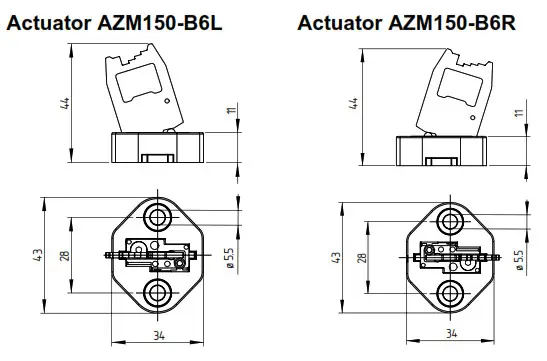
The actuators AZM150-B1 and AZM150-B5 are preferably used for sliding and removable safety guards. For hinged guards, the AZM150B6L or AZM150-B6R actuator.
When the switch is fitted on a hinged safety guard, please ensure that the point of rotation is located within the range of the upper surface of the safety switch, in which the actuator hook is inserted (refer to table).
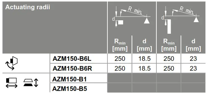
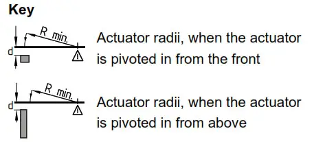
The axis of the hinge must be d mm above and in a parallel plane to the top surface of the safety switch. The basis set provides a minimum radius of Rmin.
Setting screw
The AZM150-B6L or AZM150-B6R actuator is set to the smallest radius in the factory. To increase the radius, the setting screws a + b must be turned by means of a hexagonal key A/F 2 mm.
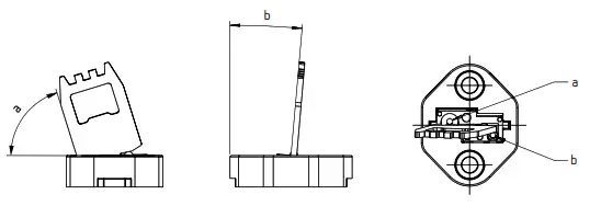
Strength of the actuator screws 5.6.
Actuator AZM150-B1
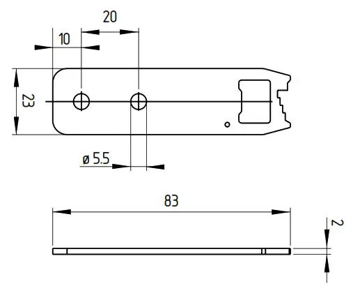
Installation position with actuator inserted (all measurements ± 0.3 mm)
Actuator AZM150-B5
Installation position with actuator inserted (all measurements ± 0.3 mm)
Installation position with actuator inserted (all measurements ± 0.3 mm)

Accessories
| Designation / description | Ordering code | |
| Triangular key | TK-M5 | 1.01E+08 |
| Lockout tag | SZ150-1 | 1.53E+08 |
| Cable gland | M20 x 1,5 | on request |
| Tamperproof screws | M5 x 15, 2 (incl. washers) | on request |
Electrical connection
General information for electrical connection
The electrical connection may only be carried out by authorized personnel in a de-energized condition.If the risk analysis indicates the use of a monitored interlock they are to be connected in the safety circuit with the contacts indicated with the symbol.
Appropriate cable glands with a suitable degree of protection are to be used. The desired insertion opening should be opened with a suitable tool.
After wiring, the wiring compartment must be cleaned (i.e. remove excess cables, etc.).
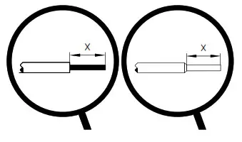
Max. cable section: 0.25 … 1.5 mm²
(incl. conductor ferrules without plastic collar)
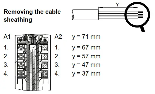
Settle length x of the conductor: 6 mm
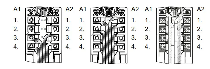
Contact Options
Contacts shown in a de-energized condition and with the actuator inserted.
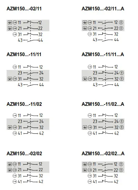
Key
Magnetic contact![]() Positive break NC contact
Positive break NC contact![]() Monitoring the interlock according to EN ISO 14119
Monitoring the interlock according to EN ISO 14119![]() Actuated
Actuated
Wiring examples
When routing the cables, account for an offset of the terminals at the left and right terminal screws.
Route the cables neatly next to or above the other cables.
Set-up and maintenance
Functional testing
The safety function of the safety components must be tested. The following conditions must be previously checked and met:
- Fitting of the solenoid interlock and the actuator
- Check the integrity of the cable entry and connections
- Check the switch enclosure for damage
- Check that both the cover-side and rear manual releases are in the starting position
Maintenance
A regular visual inspection and functional test, including the following steps, is recommended:
- Check for tight installation of the actuator and the switch
- Remove particles of dust and soiling
- Check cable entry and connections
Adequate measures must be taken to ensure protection against tampering either to prevent tampering of the safety guard, for instance by means of replacement actuators.
Damaged or defective components must be replaced.
Disassembly and disposal
Disassembly
The safety switchgear must be disassembled in a de-energized condition only.
Disposal
The safety switchgear must be disposed of in an appropriate manner in accordance with the national prescriptions and legislation.
EU Declaration of conformity
| Original | SCHMERSAL Industrial Switchgear (Shanghai) Co., Ltd. Cao Ying Road 3336 201712 Shanghai / Qingpu P.R.CHINA http://www.schmersal.com.cn |
We hereby certify that the hereafter described components both in their basic design and construction conform to the applicable European Directives.
Name of the component: AZM150
Type: See ordering code
Description of the component: An interlocking device with electromagnetic interlock for safety functions
Relevant Directives: Machinery Directive EMC-Directive RoHS-Directive 2006/42/EC 2014/30/EU 2011/65/EU
Applied standards: EN 60947-5-1:2017 EN ISO 14119:2013
A person authorized for the compilation of the technical documentation: Oliver Wacker Möddinghofe 30 42279 Wuppertal
Place and date of issue: Shanghai, April 1, 2021

Authorized signature
Managing Director
The currently valid declaration of conformity can be downloaded from the internet at products.schmersal.com.

| K.A. Schmersal GmbH & Co. KG Möddinghofe 30, 42279 Wuppertal Germany Phone: +49 202 6474-0 Telefax: +49 202 6474-100 E-Mail: [email protected] Internet: www.schmersal.com | Production site: SCHMERSAL Industrial Switchgear (Shanghai) Co., Ltd. Cao Ying Road 3336 201712 Shanghai / Qingpu, P.R.CHINA Phone: +86-21-63 75 82 87 Fax: +86-21-69 21 43 98 E-Mail: [email protected] Internet: www.schmersal.com.cn |


