![]() INSTALLATION INSTRUCTIONS FOR DCP-CZM CONVENTIONAL ZONE MODULE
INSTALLATION INSTRUCTIONS FOR DCP-CZM CONVENTIONAL ZONE MODULE
The information contained in this installation instruction is to be used as quick reference guide. For detailed system information, refer to the panel’s installation manual.
GENERAL DESCRIPTION
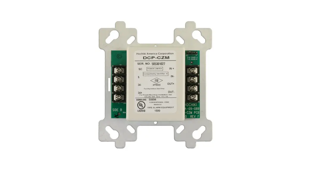
This instruction applies to the Conventional Zone Module (DCP-CZM), which is to be connected to a Signal Line Circuit (SLC). The module allows the analog panel to interface and monitor dry contacts such as pull stations and two-wire conventional smoke detectors. The “DCP-CZM” is addressed through the communication line of the system and transmits the status of one zone of devices to the panel. Status conditions are reported as normal, open or alarm. It supervises the external power supply as well as the entire zone of devices.
NOTE: Please reference the 2 wire detector compatibility matrix on the proceding page for a complete list of devices approved for use with the “DCP-CZM”
MOUNTING REQUIREMENTS
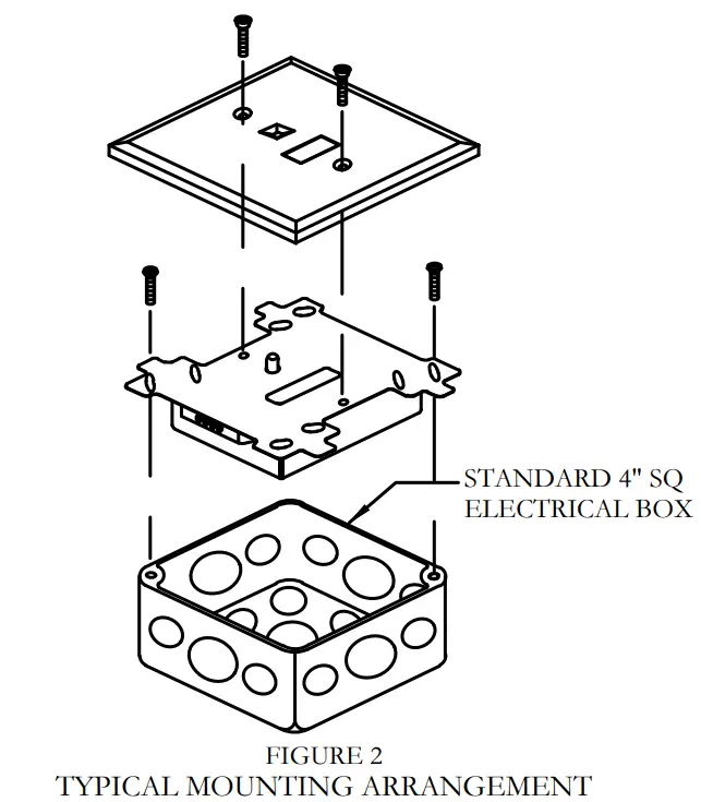
The (DCP-CZM) Conventional Zone module is mounted as shown in Figure 2 on page 1 of this instruction.
WIRING
NOTE: All wiring must conform to local codes, ordinances and regulations.
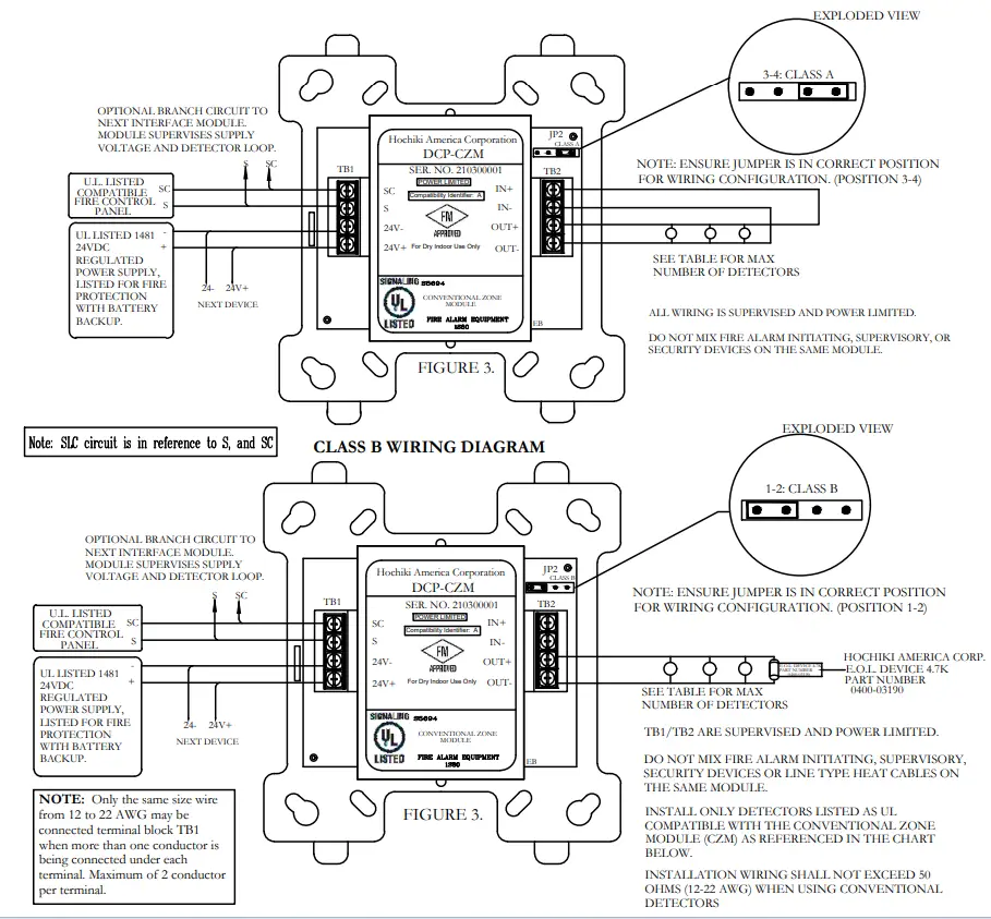
- Install module wiring in accordance with the job drawings and appropriate wiring diagram (see Fig.3).
- Secure the module to a U.L. listed electrical box (supplied by installer), as shown in Figure 2.
CAUTION !
Install the modules in this instruction in accordance with applicable NFPA standards, local codes, and the authorities having jurisdiction. Failure to follow these instructions may result in failure of the system to operate as intended. Hochiki America is not responsible for modules that have been improperly installed, tested, or maintained.
CAUTION !
To ensure proper operation connect this module to a compatible Fire Control Panel only. Refer to panel instructions for proper connection and compatibility.
CAUTION !
If this module will be installed in an existing operation system, inform the operator and local authority that the system will be temporarily out of service. Disconnect power to the control panel before installing the module
SPECIFICATIONS
| SIC Applied Voltage | Rated Range 25.3 — 39 VDC |
| SW Current Consumption | Alarm 6.OmA Normal Standby 500pA |
| Auxiliary Applied Voltage | 24VDC |
| 2—Wire Detector Loop Current (Auxiliary Supply) | Standby Detector Load — 2mA Max Alarm (Short across detector line) — 60mA Max |
| Maximum Ouput Current (OUT+/OUT—, IN+/IN—) | 2A ® 30VDC |
| EOL Device for OUT+ & OUT— | HOCHIKI AMERICA CORP. EOL Part No. 0400-03190 4.7KO, 1/4watt, 1/4inch |
| Alarm threshold level | <1.5KQ |
| Wiring OK threshold level | >2.51a1 & <61(0 |
| Open Circuit threshold level | >10KO |
| Max. 2—wire Conventional Detector Loop Resistance | 500 (for both legs) |
| Visual Indicator (Status LED) | Bi—color LED — Green & Red Color & Mode — Selected and Programmed by Control Panel’s software |
| Operating Temperature Range | 0°C (32°F) -, 49°C (120°F) |
| Storage Temperature Range | _30°C (-22°F) — 70°C (158°F) |
| Maximum Relative Humidity | 90% RH non—condensing |
| Environment | Indoor dry use only |
| Dimensions | 4.2″W X 4.7″H X .85″D |
| Weight | Approximately 3.0 ounces |
NOTE:
An average of 6.75mA (communication current) per loop of SLC devices, must be factored into the panel battery backup calculations.
NOTE: Maximum Ripple Voltage 2VDC P-P
HOCHIKI AMERICA CORPORATION 7051 VILLAGE DRIVE, SUITE 100 BUENA PARK, CA 90621-2268
HA-06-101 DWG. # (PG 1 OF 2, 09/21) PART# 1700-10170
CLASS A WIRING DIAGRAM
Compatible Two Wire Detectors for use with the CZM with zone identifier A:
| Detector Model | Detector Identifier | Detector Type | Base Model | Base lndetifier | Max Detectors |
| SLR-241-1 | HD-3 | Photoelectric w/heat | NS4/NS6-220/-224 | 1-113-3/HB-5 | 25 |
| SLR-24V | HD-3 | Photoelectric | NS4/NS6-220/-224 | HB-3/HB-5 | 25 |
| SLR-835/-835W | HD-3 | Photoelectric (8-35V) | NS4/NS6-220/-224 | HB-3/HB-5 | 25 |
| SLR-835E1/-835HW | HD-5 | Photoelectric (8-35V) w/thermal | NS4/NS6-224/-224/-220/-220 | HB-3/HB-5 | 25 |
| SLR-83513-2/-2W | HD-6 | Photoelectric (8-35V) (baseless) | N/A | N/A | 25 |
| SLR-835BH-2/-2W | HD-6 | Photoelectric (8-35V) w/thermal (baseless) | N/A | N/A | 25 |
| SLV-24/-24N/-24V | HD-3 | Photoelectric | NS4-224, NS6-224 | HB-5 | 25 |
| SLV-24/-24N/-24V | HD-3 | Photoelectric | NS4-220, NS6-220 | HB-3 | 25 |
| SOC-24V/-24VN /-24VW | HD-3 | Photoelectric (8-35V) | NS4/NS6-100,NS4/NS6-220/-221/-224 | HB-55/HB-3/HB-4/HB-5 | 25 |
| DCD-135/-190 | HD-3 | Heat Fixed Temp/Rate of Rise | NS4-224, NS6-224 | HB-5 | 25 |
| 1)CD-135/-190 | HD-3 | Heat Fixed Temp/Rate of Rise | NS4-220, NS6-220 | HB-3 | 25 |
| SOE-24V/-24V(VI-fl) | HD-3 | Photoelectric (8-35V) | NS4/NS6-100/-220/-221/-224 | 1-1B-55/HB-3/1-1B-4/HB-5 | 25 |
| SOE-241-1/-24H(WHT) | HD-3 | Photoelectric w/ Heat (8-35V) | NS4/NS6-100/-220/-221/-224 | HB-55/HB-3/1113-4/HB-5 | 25 |
NOTE: BASES MAY HAVE “W” SUFFIX FOR WHITE COLOR
Compatible Linear Heat Detection Cable for use with the CZM:
| Manufacturer | Model | Description | Maximum Lenght | ||
| Proline Protection Systems | TI-I 68 | Fixed Temp. line type heat detector cable 155°F | (68°C) | 8,000ft. | (2,438m) |
| Proline Protection Systems | TI-1 88 | Fixed Temp. line type heat detector cable 190°F | (88°C) | 8,000ft. | (2,438m) |
| Proline Protection Systems | TI-1 105 | Fixed Temp. line type heat detector cable 221°F | (105°C) | 8,000ft. | (2,438m) |
One Year Limited Warranty
Hochiki America (HA) warrants its digital communication modules to be in conformance with it’s own plans and specifications and to be free from defects in materials and workmanship under normal use and service for a period of one (1) year from date of delivery. All warranties are void and HA is not obligated to repair or replace equipment which has been repaired by others, abused, improperly installed, altered or otherwise misused or damaged or exposed to conditions outside the products specifications in any way. HA will not be responsible for any dismantling, reassembling or re-installation charges. Please contact HA’s Sales department for proper procedure for claims and return of merchandise. This warranty is in lieu of all other warranties expressed or implied.
HA-06-101
DWG. #
(PG 2 OF 2, 09/21)
PART# 1700-10170
[2] HA-06-101 CZM MODULE INSTALL INSTR_Rev-09-21-PAGE2 (2 OF 2)


